

 Download PDF
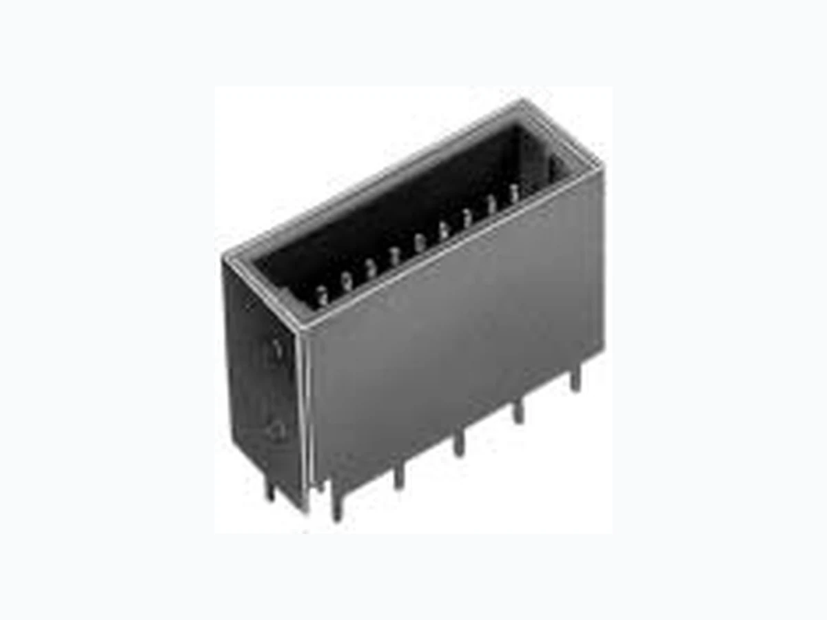
GT8-2428SCF HIROSE
Document overview
- PDF pages: 4
Technical content
Page 1
Antenna, Sensor, and Communications Trunk Line Connections
GT8 Series
— High-Pressure Connectors —
<GT8, GT8A, and GT8Z>
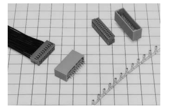
Features
Crimp Terminals Use of an air-tight dimple construction at the contact portion serves to prevent oxidation of the contact portion. F Connector Housing Terminal number markings appear in a large size in consideration of insertion processing. Form designed to prevent erroneous insertion. M Connectors Designed with escape holes for washing liquid to escape so that secondary soiling may be prevented when the board has been washed. The surrounding wall of the terminal has been constructed higher than the terminal so as to prevent terminal bending. Miscellaneous The F connector housing fits entirely inside of the M connector to prevent incomplete insertion and prevents
[?GOSHIRI=?twisting] and other problems. The F connector is guarded so that there is no slanting nor contact movement, and the connector is resistant to vibration. The color of the F connector housing and the M connector have been changed to prevent incomplete insertion.
Applications
Internal connections of mobile units.
2003.7
Page 2
F Connectors
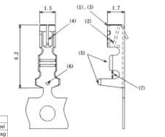
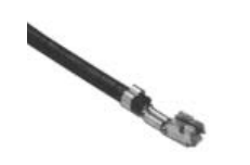
Terminals
| Part Number | CL No. | Material | Finish | Packaging |
|---|---|---|---|---|
| GT8-2428SCF | 758-0001-8 | Phosphor bronze | Tin plating | 10,000 pcs. per reel |
| GT8-2428SC | 758-0002-0 | Phosphor bronze | Tin plating | 100 pcs. per bag |
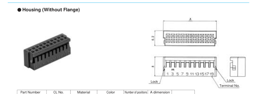
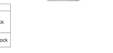
| Part Number | CL No. | Material | Color | Number of positions | A dimension | |
|---|---|---|---|---|---|---|
| GT8-14DS-2C | 758-0018-0 | PBT | Dark gray | 14 | 15.8 | With lock |
| GT8-20DS-2C | 758-0003-3 | 20 | 21.8 | |||
| GT8-24DS-2C | 758-0005-9 | 24 | 25.8 | |||
| GT8A-20DS-2C | 758-0011-1 | 20 | 21.8 | Without lock | ||
| GT8A-24DS-2C | 758-0012-4 | 24 | 25.8 |
Housing (With Flange)
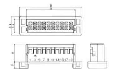
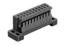
| Part Number | CL No. | Material | Color | Number of positions | A dimension | B dimension |
|---|---|---|---|---|---|---|
| GT8Z-14DS-2C | 758-0009-0 | PBT | Dark gray | 14 | 15.8 | 22 |
| GT8Z-20DS-2C | 758-0007-4 | 20 | 21.8 | 28 | ||
| GT8Z-24DS-2C | 758-0008-7 | 24 | 25.8 | 32 |
Note: This product mates with GT8- or GT8A-\*DP-2DSA.
Page 3
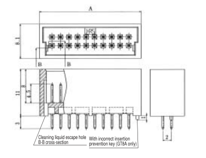
M Connectors
Board Type
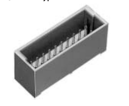
| Part Number | CL No. | Number of potions | A dimension | |
|---|---|---|---|---|
| GT8-14DP-2DSA | Under development | 14 | ---- | |
| GT8-20DP-2DSA | 758-0004- 6 | 20 | 23.8 | |
| GT8-24DP-2DSA | 758-0006-1 | 24 | 27.8 | |
| GT8A-14DP-2DSA | 758-0010-9 | 14 | 17.8 | Incorrect insertion prevention key |
| GT8A-20DP-2DSA | 758-0013-7 | 20 | 23.8 | |
| GT8A-24DP-2DSA | 758-0014-0 | 24 | 27.8 |
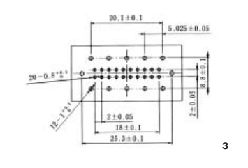
BRecommended PCB Mounting Pattern
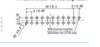
Material Finish PBT Color: Light gray Brass Tin plating
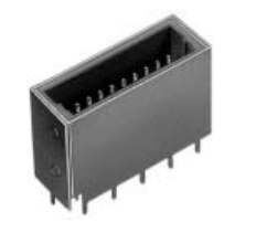
Type With Feed-through Capacitor
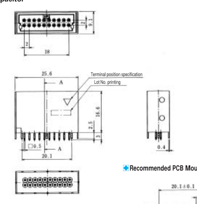
| Part Number | CL No. |
|---|---|
| GT8C-20DP-2DSA | 758-0015-2 |
\* Capacitor value of 1,000 pF is standard. \* Should you have other requirements, please contact a Hirose Electric account representative.
Page 4
B Termination Tools
User's manuals are available. Please contact a Hirose Electric account representative.
Automatic Crimping Machine
Specifications
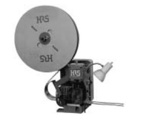
| Item | Specification | Remarks |
| Specification | 1.5ton | |
| Stroke length | 30mm | |
| Number of strokes | 200 spm (50 Hz) | 240 spm (60 Hz) |
| Wight | 75 kg | |
| Motor | 0.2kw | AC100V |
| Crimping speed | 2,000 to 4,000 pcs. per Hour |
Part number CM-105
Hand Tool
\* Crimp height setting tables are available for each cable type. Please contact your nearest Hirose Electric account representative. Different cables will requires different crimp height settings.