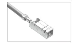
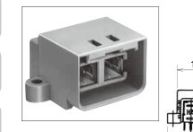
GT5 HIROSE

Document overview

  • PDF pages: 22
Technical content

Page 1

For Antenna

Patented

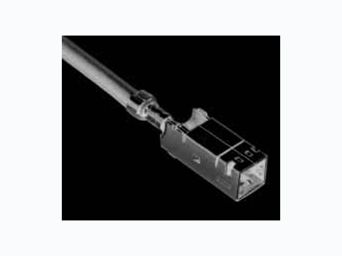
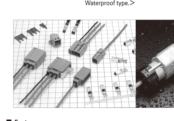
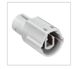
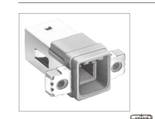
In-vehicle shielding connector with twin crimp technology

GT5 Series

---- Connectors for coaxial cables ----

<In-line, board mounted, combinations of coaxial cable with signal/power,

Waterproof type.>

PDF page 1 diagram
Features

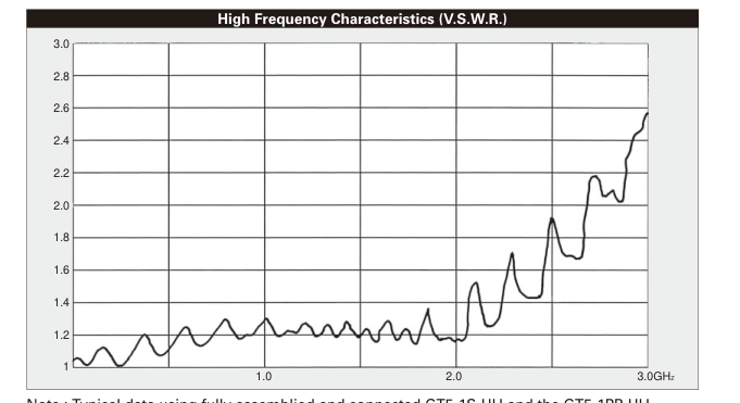
USCAR specified connector as SAE/USCAR-19 Low cost cable assembly Highly efficient and reliable one step crimp termination "Twin Crimp TM" allows high volume production with semi-automatic equipment. Space-saving design Excellent high frequency performance Refer to V.S.W.R. data on the following pages.

Applications

In-car communication, car sensors (temperature, pressure), automotive audio systems, GPS antenna systems, RACS antenna audio/video antenna systems, CRT displays, medical and measuring instrumentation, variety of communication equipment, office automation equipment, LAN systems.

In cases where the application will demand a high level of reliability, such as automotive, please contact a company representative for further information.

Page 2

B Test Data (Using 1.5D-2V Type cable)

PDF page 2 diagram
Note : Typical data using fully assemblied and connected GT5-1S-HU and the GT5-1PP-HU.

B Termination sequence

1. Strip the cable 3.5 5 9.5 3. Insert the terminal in the housing until fully locked. Push in the terminal with cable in the housing until the housing lance locked.
2. Crimp the cable to the terminal. 4. Fully insert the retainer. Push in the retainer until locked.

Page 3

PDF page 3 diagram
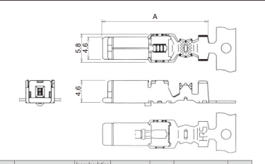
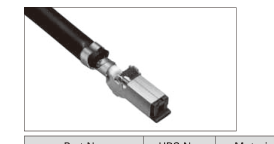
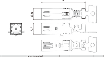
Terminals for coaxial cable

F Connector Terminals

PDF page 3 diagram
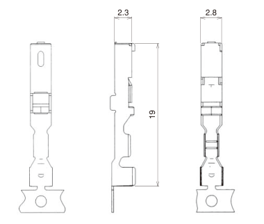
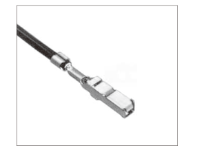
Part No. HRS No. Material/Plating or Color Conductor Size (AWG) Inner Insulation Diameter Outer Diameter A Packaging RoHS
GT5-30/0.7-1.5SCF(70) 755-0065-1 70 Insulator:PBT/Dark Gray Center terminal:Phosphor bronze/ Tin plating Outer terminal:Brass/Tin plating 30 AWG Ø0.6 to 0.9 Ø1.4 to 1.8 22.7 1,300 pcs/reel YES
GT5-2428/1.1-2.2SCF 755-0123-6-70 24 to 28 AWG Ø1.0 to 1.4 Ø2.0 to 2.4 21.7
GT5-2428/1.6-2.5SCF(70) 755-0078-3 70 Ø1.5 to 2.0 Ø2.3 to 2.7
GT5-30/1.6-2.9SCF(70) 755-0022-9 70 30 AWG Ø2.6 to 3.4
GT5-2428/1.6-2.9SCF(70) 755-0002-1 70 24 to 28 AWG
GT5-2022/1.6-2.9SCF(70) 755-0071-4 70 20 to 22 AWG
GT5-2022/F2.7-3.5SCF(70) 755-0077-0 70 Ø2.0 to 2.5 Ø3.3 to 3.7 22.7 1,100 pcs/reel
GT5-2022/F3.3-3.8SCF(70) 755-0054-5 70 Ø2.5 to 2.9 Ø3.6 to 4.0
GT5-30/F3.3-5SCF(70) 755-0016-6 70 30 AWG Ø4.6 to 5.0
GT5-2428/F3.3-5SCF(70) 755-0012-5 70 24 to 28 AWG
GT5-2022/F3.3-5SCF(70) 755-0034-8 70 20 to 22 AWG
GT5-30/F4-5SCF(70) 755-0020-3 70 30 AWG Ø3.0 to 3.6
GT5-2428/F4-5SCF(70) 755-0024-4 70 24 to 28 AWG
GT5-2022/F4-5SCF(70) 755-0036-3 70 20 to 22 AWG

Note : Products marked with an asterisk (\*) indicate polyethylene foam insulation.

A

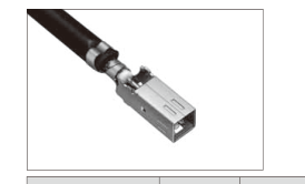
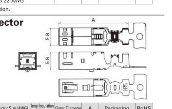
Terminals for M Connector

PDF page 3 diagram
PDF page 3 diagram
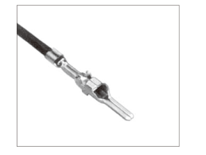
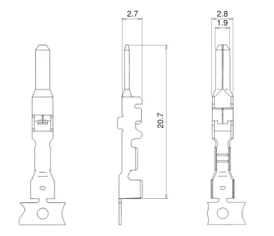
Part No. HRS No. Material/Plating or Color Conductor Size (AWG) Inner Insulation Diameter Outer Diameter A Packaging RoHS
GT5-30/0.7-1.5PCF(70) 755-0017-9 70 Insulator:PBT/Dark Gray Center terminal:Brass/Tin plating Outer terminal:Brass/Tin plating 30 AWG Ø0.6 to 0.9 Ø1.4 to 1.8 24.05 900 pcs/reel YES
GT5-30/1.6-2.9PCF(70) 755-0021-6 70 Ø1.5 to 2.0 Ø2.6 to 3.4 23.05
GT5-2428/1.6-2.9PCF(70) 755-0001-9 70 24 to 28 AWG
GT5-2022/1.6-2.9PCF(70) 755-0094-0 70 20 to 22 AWG
GT5-2022/F2.7-3.5PCF(70) 755-0076-8 70 Ø2.0 to 2.5 Ø3.3 to 3.7 24.05
GT5-2022/F3.3-3.8PCF(70) 755-0053-2 70 Ø2.5 to 2.9 Ø3.6 to 4.0
GT5-30/F3.3-5PCF(70) 755-0015-3 70 30 AWG Ø4.6 to 5.0
GT5-2428/F3.3-5PCF(70) 755-0011-2 70 24 to 28 AWG
GT5-2022/F3.3-5PCF(70) 755-0033-5 70 20 to 22 AWG
GT5-30/F4-5PCF(70) 755-0019-4 70 30 AWG Ø3.0 to 3.6
GT5-2428/F4-5PCF(70) 755-0023-1 70 24 to 28 AWG
GT5-2022/F4-5PCF(70) 755-0035-0 70 20 to 22 AWG
PDF page 3 diagram
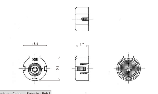
Note : Products marked with an asterisk (\*) indicate polyethylene foam insulation.

Terminals for Low-insertion M Connector

PDF page 3 diagram
Part No. HRS No. Material/Plating or Color Conductor Size (AWG) Inner Insulation Diameter Outer Diameter A Packaging RoHS
GT5L-30/0.7-1.5PCF(70) 755-0068-0 70 Insulator:PBT/Dark Gray Center terminal:Brass/Tin plating Outer terminal:Brass/Tin plating 30 AWG Ø0.6 to 0.9 Ø1.4 to 1.8 24.05 900 pcs/reel YES
GT5L-2428/1.6-2.5PCF(70) 755-0079-6 70 24 to 28 AWG Ø1.5 to 2.0 Ø2.3 to 2.7 23.05
GT5L-30/1.6-2.9PCF(70) 755-0067-7 70 30 AWG Ø2.6 to 3.4
GT5L-2428/1.6-2.9PCF(70) 755-0066-4 70 24 to 28 AWG

Page 4

PDF page 4 diagram

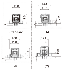
1 Pos. for coaxial cable

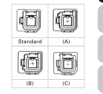
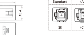
Standard (A)
(B) (C)

F Connectors

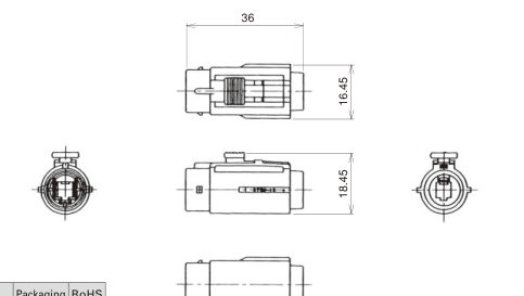
Housings

PDF page 4 diagram
PDF page 4 diagram

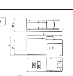
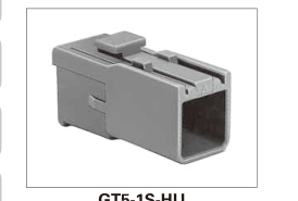
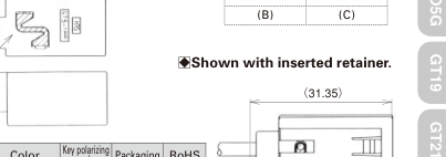
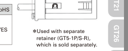
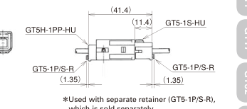
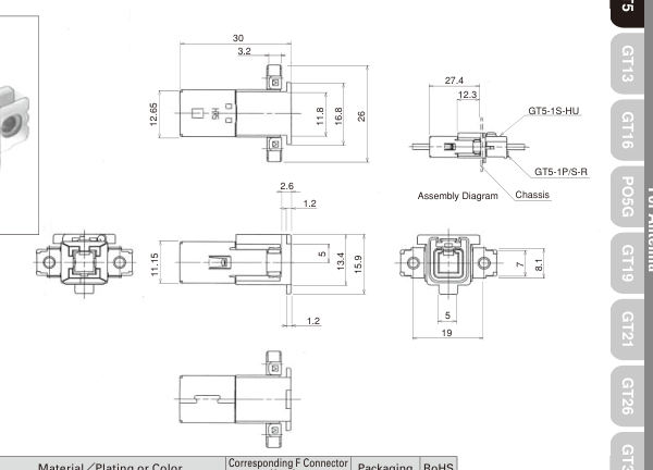
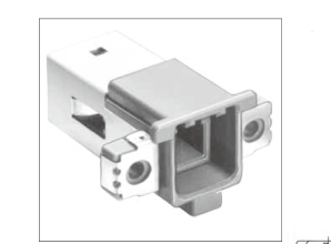
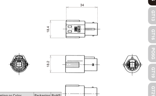
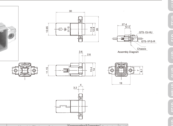
GT5-1S-HU

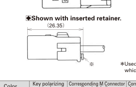
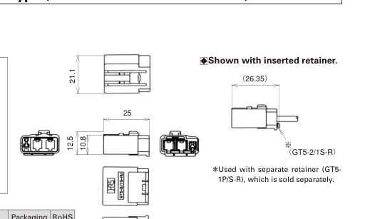
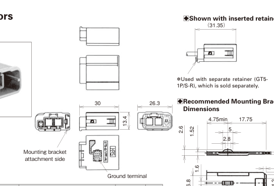
\*Used with separate retainer (GT5-1P/S-R), which is sold separately.

Part No. HRS No. Material Color Key polarizing code Corresponding M Connector Housing- In-line Corresponding M Conn Assembly- Board Mou ector Packaging nting RoHS
GT5-1S-HU 755-0004-7 PBT Light Gray Standard GT5-1PP-HU(70) GT5-1P-DS(70) 1 YES
GT5-1S-HU(A) 755-0037-6 Brown (A) GT5-1PP-HU(A)(70) GT5-1P-DS(A)(70)
GT5-1S-HU(B) 755-0038-9 Green (B) GT5-1PP-HU(B)(70) GT5-1P-DS(B)(70)
GT5-1S-HU(C) 755-0080-5 Blue (C) GT5-1PP-HU(C)(70) GT5-1P-DS(C)(70)

\*Mating Table(M Connectors) Prease use a matching key tipe.

PDF page 4 diagram

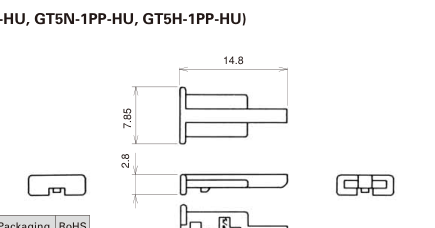
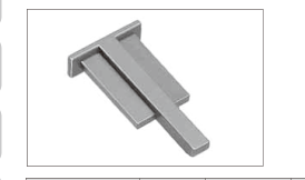
Retainer ( Used with : GT5-1S-HU, GT5-1PP-HU, GT5N-1PP-HU, GT5H-1PP-HU)

PDF page 4 diagram
Part No. HRS No. Material Color Packaging RoHS
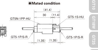
GT5-1P/S-R 755-0006-2 PBT Dark Gray 1 YES

Housing (Retainer is not required)

PDF page 4 diagram
PDF page 4 diagram

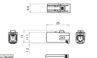
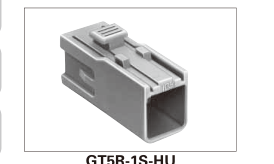
GT5R-1S-HU

Part No. HRS No. Material Color Packaging RoHS
GT5R-1S-HU 755-0047-0 PBT Light Gray 1 YES

Page 5

M Connectors

PDF page 5 diagram
PDF page 5 diagram

Housings

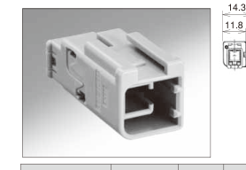
PDF page 5 diagram
PDF page 5 diagram
PDF page 5 diagram
PDF page 5 diagram
Part No. HRS No. Corresponding F Connector Housing Material/Plating Color Key polarizin code g Packaging RoHS
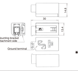
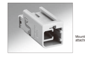
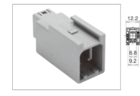
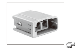
GT5-1PP-HU(70) 755-0005-0 70 GT5-1S-HU Housing:PBT Ground terminal: Phosphor bronze/ Tin plating Light Gray Standard 1 YES
GT5-1PP-HU(A)(70) 755-0039-1 70 GT5-1S-HU(A) Brown (A)
GT5-1PP-HU(B)(70) 755-0040-0 70 GT5-1S-HU(B) Green (B)
GT5-1PP-HU(C)(70) 755-0103-9 70 GT5-1S-HU(C) Blue (C)
PDF page 5 diagram

Note 1 : Refer to pages 27 for panel mounting in-line bracket. Note 2 : Please use a mating F connector housing of a matching key type.

PDF page 5 diagram

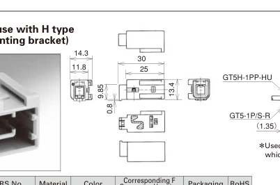
Housings ( For use with H type

PDF page 5 diagram
PDF page 5 diagram

which is sold separately.

Part No. HRS No. Material Color Corresponding F Connector Housing Packaging RoHS
GT5H-1PP-HU(10) 755-0093-7 10 PBT Light Gray GT5-1S-HU GT5R-1S-HU 1 YES
PDF page 5 diagram

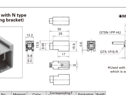
Housing ( For use with N type

mounting bracket)

PDF page 5 diagram
PDF page 5 diagram

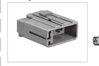
\*Used with separate retainer (GT5-1P/S-R), which is sold separately.

Part No. HRS No. Material Color Corresponding F Connector Housing Packaging RoHS
GT5N-1PP-HU 755-0090-9 PBT Light Gray GT5-1S-HU GT5R-1S-HU 1 YES

Page 6

Housings

[

]

Panel mounting,

PDF page 6 diagram

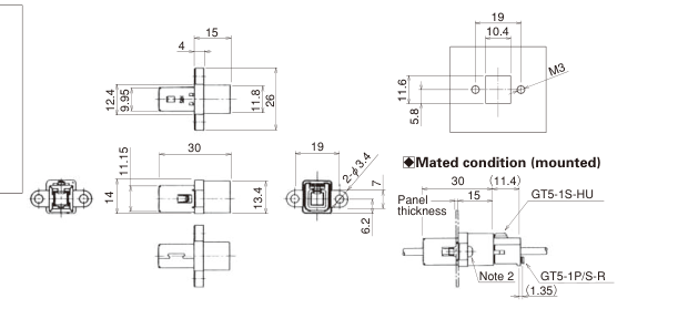
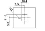
BRecommended Panel Cut-out

PDF page 6 diagram
Part No. HRS No. Material/Plating or Color Corresponding F Connector Housing Packaging RoHS
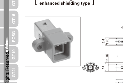
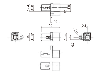
GT5A-1PP-HU(70) 755-0025-7 70 Housing:PBT/Light Gray Ground terminal:Brass/Tin plating GT5-1S-HU GT5R-1S-HU 1 YES

Note 1 : Retainer is not required. Note 2 : Use JIS B 1111 and 1101 M3 screws for the mounting screws.

PDF page 6 diagram

BRecommended Panel Cut-out

PDF page 6 diagram
PDF page 6 diagram
Part No. HRS No. Material/Plating or Color Corresponding F Connector Housing Packaging RoHS
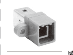
GT5P-1PP-HU(70) 755-0030-7 70 Housing:PBT/Light Gray Ground terminal:Brass/Tin plating GT5-1S-HU GT5R-1S-HU 1 YES

Note 1 : Retainer is not required. Note 2 : Use JIS B 1111 and 1101 M3 screws for the mounting screws.

Page 7

PDF page 7 diagram
PDF page 7 diagram
Part No. HRS No. Material/Plating or Color Corresponding F Connecto Housing r Packaging RoHS
GT5B-1PP-HU(70) 755-0051-7 70 Housing:PBT/Light Gray Ground terminal:Phosphor bronze/Tin plating GT5-1S-HU GT5R-1S-HU 1 YES

Note 1 : Retainer is not required. Note 2 : Use JIS B 1115 and 1122 class 4, nominal diameter 3, length 6 screws for the mounting screws.

PDF page 7 diagram
PDF page 7 diagram
Part No. HRS No. Material/Plating or Color Corresponding F Connecto Housing r Packaging RoHS
GT5S-1PP-HU(70) 755-0050-4 70 Housing:PBT/Light Gray Ground terminal:Phosphor bronze/Tin plating GT5-1S-HU GT5R-1S-HU 1 YES

Note 1 : Retainer is not required. Note 2 : Use JIS B 1115 and 1122 class 4, nominal diameter 3, length 6 screws for the mounting screws.

Page 8

PDF page 8 diagram
PDF page 8 diagram

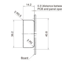
Board Mounting Type

PDF page 8 diagram
PDF page 8 diagram
PDF page 8 diagram

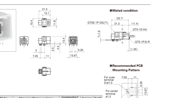
BMated condition

PDF page 8 diagram

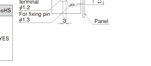
BRecommended PCB

PDF page 8 diagram
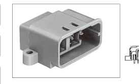
Part No. HRS No. Material/Plating or Color Color Key polarizing code Corresponding F Connector Housing Packaging RoHS
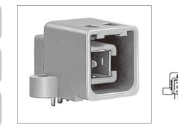
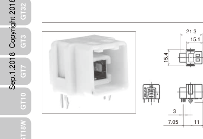
GT5-1P-DS(70) 755-0007-5 70 Housing:PBT/ー Center terminal:Brass/Tin plating Insulator:PBT/Dark Gray Outer terminal:Phosphor bronze/Tin plating Light Gray Standard GT5-1S-HU 1 YES
GT5-1P-DS(A)(70) 755-0041-3 70 Brown (A) GT5-1S-HU(A)
GT5-1P-DS(B)(70) 755-0042-6 70 Green (B) GT5-1S-HU(B)
GT5-1P-DS(C)(70) 755-0083-3 70 Blue (C) GT5-1S-HU(C)

Note 1 : Use JIS B 1115 and 1122 class 4, nominal diameter 3, length 6 screws (for a board thickness of 1.6 mm) for the mounting screws. Note 2 : Please use a mating F connector housing of a matching key type.

PDF page 8 diagram
PDF page 8 diagram
PDF page 8 diagram
Part No. HRS No. Material/Plating or Color Corresponding F Connector Housing Packaging RoHS
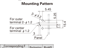
GT5EC-1P-DS(71) 755-0125-1 71 Housing:PA/Natural Center terminal:Brass/Tin plating Insulator:PA/Black Outer terminal:Phosphor bronze/Tin plating Fixing pin:Brass/Tin plating GT5-1S-HU GT5R-1S-HU 1 YES

Page 9

PDF page 9 diagram
PDF page 9 diagram

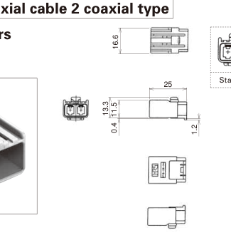
1 Pos. for coaxial cable 2 coaxial type

PDF page 9 diagram

F Connectors

Standard (A) (B) (C)

Housing

PDF page 9 diagram
PDF page 9 diagram
Part No. HRS No. Material Color Key polarizing code Packaging
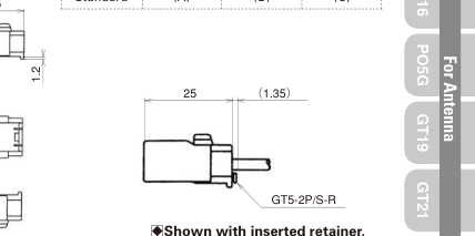
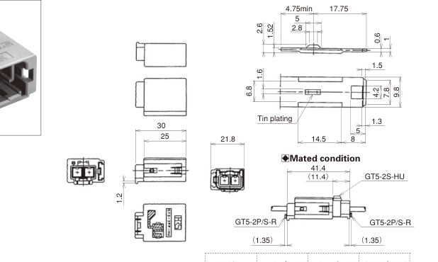
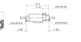
GT5-2S-HU 755-0044-1 PBT Light Gray Standard 1
GT5-2S-HU(A) 755-0059-9 Brown (A)
GT5-2S-HU(B) 755-0060-8 Green (B)
GT5-2S-HU(C) 755-0097-8 Blue (C)

Note 1 : Assemble main parts with separate retainer (GT5-2P/S-R). Note 2 : Please use a mating F connector housing of a matching key type.

M Connectors

Housings[Panel Mounted Housing]

PDF page 9 diagram

Packaging RoHS

YES

BRecommended Mounting Bracket dimensions.

PDF page 9 diagram
Standard (A) (B) (C)
Part No. HRS No. Material/Plating Color Key polarizing code Packaging RoHS
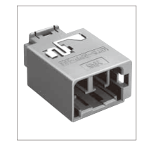
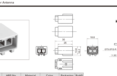
GT5-2PP-HU(70) 755-0045-4 70 Housing:PBT Ground terminal:Phosphor bronze /Tin plating Light Gray Standard 1 YES
GT5-2PP-HU(A)(70) 755-0063-6 70 Brown (A)
GT5-2PP-HU(B)(70) 755-0064-9 70 Green (B)
GT5-2PP-HU(C)(70) 755-0099-3 70 Blue (C)

Note 1 : Assemble main parts with separate retainer (GT5-2P/S-R). Note 2 : Please use a mating F connector housing of a matching key type.

Page 10

PDF page 10 diagram

Housings

BMated condition

PDF page 10 diagram
Part No. HRS No. Material Color Packaging
GT5N-2PP-HU 755-0055-8 PBT Light Gray 1

RoHS YES

Note : Assemble main parts with separated retainer (GT5-2P/S-R).

PDF page 10 diagram

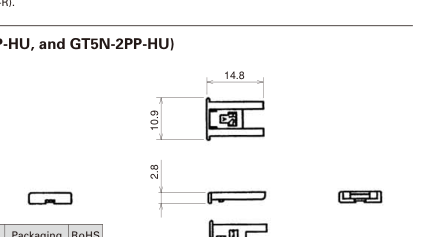
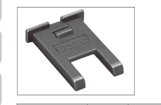
Retainer ( Used with GT5-2S-HU, GT5-2PP-HU, and GT5N-2PP-HU)

PDF page 10 diagram
Part No. HRS No. Material Color Packaging RoHS
GT5-2P/S-R 755-0046-7 PBT Dark Gray 1 YES
PDF page 10 diagram

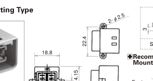
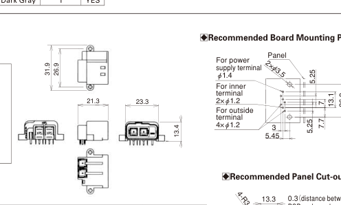
Board Mounting Type

3 3 3 3
Standard (A) (B) (C)
PDF page 10 diagram

BRecommended Board

BMated condition (mounted)

Mounting Pattern

PDF page 10 diagram

Panel

PDF page 10 diagram
PDF page 10 diagram

GT5-2P/S-R

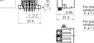
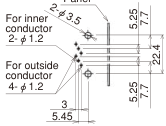
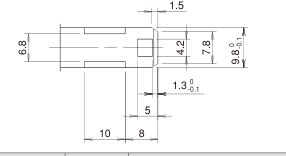
14.05 2-R 0.3 0.7 19.2 22.4 2-R3.2 Board 14.05 2-R 0.3 0.7 20.2 19.2 22.4 2-R3.25 3.6 8.2 5 Board 1144 .0055 2-R 3.2255 0.3 0.7 R 22 19.2 22.4 2200. R2.33 Boardd 11..55 3.6 14.05 2-R 0.3 0.7 20.2 19.2 22.4 8.2 2-R3.25 11.8
GT5-2P-DS (70) GT5-2P-DS (A)(70) GT5-2P-DS (B)(70) GT5-2P-DS (C)(70)
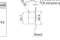
Recommended Panel Cut-out
Part No. HRS No. Material/Plating or Color Color Key polarizing code Packag ing RoHS
GT5-2P-DS(70) 755-0043-9 70 Housing:PBT/ー Center terminal:Brass/Tin plating Insulator:PBT/Dark Gray Outer terminal:Phosphor bronze/Tin plating Light Gray Standard 1 YES
GT5-2P-DS(A)(70) 755-0061-0 70 Brown (A)
GT5-2P-DS(B)(70) 755-0062-3 70 Green (B)
GT5-2P-DS(C)(70) 755-0101-3 70 Blue (C)

Note 1 : Housing. Note 2 : Use JIS B 1115 and 1122 class 4, nominal diameter 3, length 6 screws.

Page 11

Terminals for Power Supply

Terminals for F Connector

PDF page 11 diagram
PDF page 11 diagram
Part No. HRS No. Material Plating Conductor Size (AWG) Outer Diameter Packaging RoHS
GT7-2022SCF(70) 757-0001-1 70 Copper alloy Tin plating 20 to 22 AWG Ø1.4 to 2.4 5,000 pcs/reel YES
GT7A-2022SCF(70) 757-0003-7 70 Ø2.6 to 3.1 3,000 pcs/reel

Note 1 : Sold in reel. (See above table for number of Packaging.) Note 2 : This component is used only with applicable HRS housings.

Terminals for M Connector

PDF page 11 diagram
PDF page 11 diagram
Part No. HRS No. Material Plating Conductor Size (AWG) Outer Diameter Packaging RoHS
GT7-2022PCF(70) 757-0002-4 70 Brass Tin plating 20 to 22 AWG Ø1.4 to 2.4 5,000 pcs/reel YES
GT7A-2022PCF(70) 757-0004-0 70 Ø2.6 to 3.1 3,000 pcs/reel

Note 1 : Sold in reel. (See above table for number of Packaging.) Note 2 : This component is used only with applicable HRS housings.

Page 12

Combinaton Type (2 Coaxials + 1 Power contact)

PDF page 12 diagram

F Connectors

Housing

PDF page 12 diagram
Part No. HRS No. Material Color Packaging RoHS
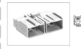
GT5-2/1S-HU 755-0009-0 PBT Light Gray 1 YES
PDF page 12 diagram

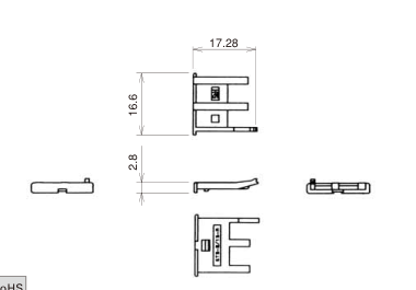
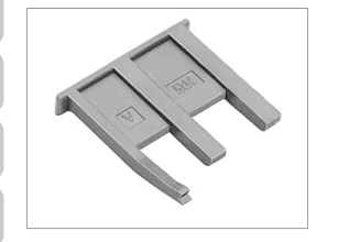
Retainer (Only for GT5-2/1S-HU)

PDF page 12 diagram
PDF page 12 diagram
Part No. HRS No. Material Color Packaging RoHS
GT5-2/1S-R 755-0003-4 PBT Dark Gray 1 YES
PDF page 12 diagram

M Connectors

Board mounting type

PDF page 12 diagram
PDF page 12 diagram
Part No. HRS No. Material/Plating or Color Packagin g RoHS
GT5-2/1P-DS(70) 755-0014-0 70 Housing:PBT/Light Gray Center terminal:Brass/Tin plating Insulator:PBT/Dark Gray Outer terminal:Phosphor bronze/Tin plating For power supply terminal:Brass/Tin plating 1 YES

Note : Use JIS B 1115 and 1122 class 4, nominal diameter 3, length 6 screws (for a board thickness of 1.6 mm) for the mounting screws.

Page 13

PDF page 13 diagram

M Connectors

Housing

PDF page 13 diagram
PDF page 13 diagram
Part No. HRS No. Material/Plating or Color Packaging RoHS
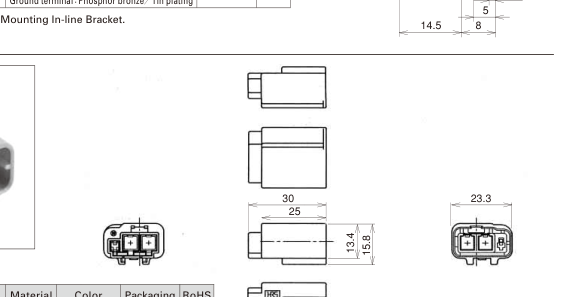
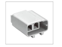
GT5-2/1PP-HU(70) 755-0008-8 70 Housing:PBT/Light Gray Ground terminal:Phosphor bronze/Tin plating 1 YES
PDF page 13 diagram

Note : Refer to pages 27 for panel Mounting In-line Bracket.

PDF page 13 diagram
Part No. HRS No. Material Color Packaging RoHS
GT5N-2/1PP-HU 755-0013-8 PBT Light Gray 1 YES
PDF page 13 diagram

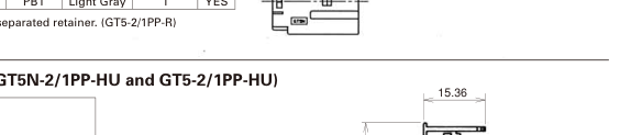
Note : Assemble main parts with separated retainer. (GT5-2/1PP-R)

PDF page 13 diagram

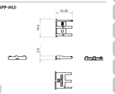
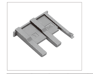
Retainer (Used with GT5N-2/1PP-HU and GT5-2/1PP-HU)

PDF page 13 diagram
Part No. HRS No. Material Color Packaging RoHS
GT5-2/1PP-R 755-0010-0 PBT Dark Gray 1 YES

Page 14

PDF page 14 diagram

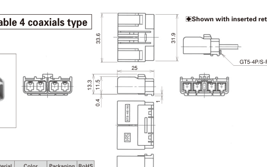
1 Pos. for coaxial cable 4 coaxials type

F Connectors

PDF page 14 diagram
Part No. HRS No. Material Color Packaging RoHS
GT5-4S-HU 755-0056-0 PBT Light Gray 1 YES
PDF page 14 diagram

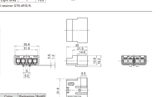
Note : Assemble main parts with separated retainer GT5-4P/S-R.

M Connectors

PDF page 14 diagram
Part No. HRS No. Material Color Packaging RoHS
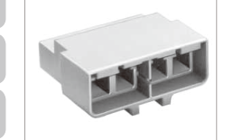
GT5N-4PP-HU 755-0057-3 PBT Light Gray 1 YES
PDF page 14 diagram

Note 1 : The product should be used with a low-force insertion/withdrawal M connector terminal. Note 2 : Assemble main parts with separated retainer GT5-4P/S-R.

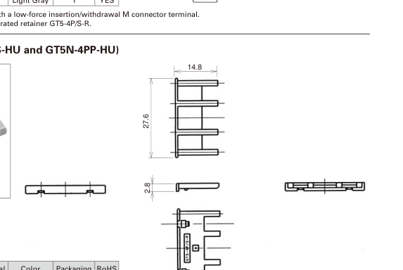
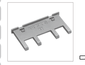
Retainer (Only for GT5-4S-HU and GT5N-4PP-HU)

PDF page 14 diagram
Part No. HRS No. Material Color Packaging RoHS
GT5-4P/S-R 755-0058-6 PBT Dark Gray 1 YES
PDF page 14 diagram

Page 15

M Connectors

PDF page 15 diagram
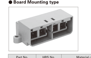
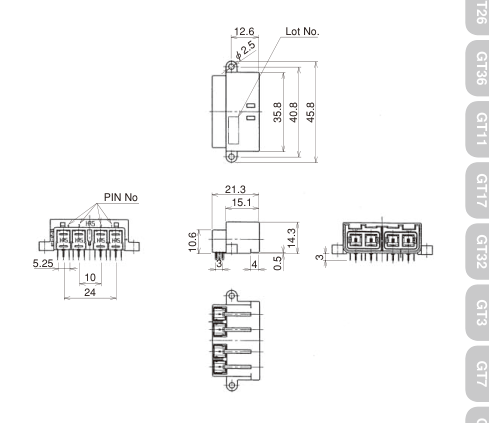
Part No. HRS No. Material/Plating or Color Packaging RoHS
GT5-4P-DS(70) 755-0087-4 70 Housing:PBT/Light Gray Center terminal:Brass/Tin plating Insulator:PBT/Dark Gray Outer terminal:Phosphor bronze/Tin plating 1 YES

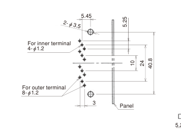
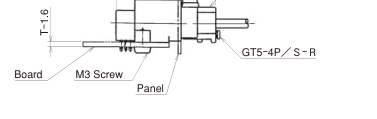
BRecommended Board Mounting Pattern

PDF page 15 diagram
PDF page 15 diagram

BMated condition (mounted)

BRecommended Panel Cut-out

PDF page 15 diagram

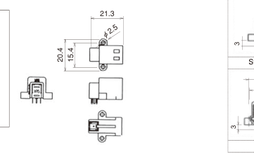
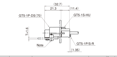
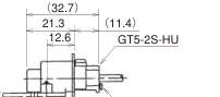
(32.7)

21.3 (11.4 ) GT5-4S-HU
PDF page 15 diagram

Page 16

1Pos. for coaxial cable with Waterproof type

F Connectors

PDF page 16 diagram

Housing

PDF page 16 diagram
Part No. HRS No. Material Color Packaging RoHS
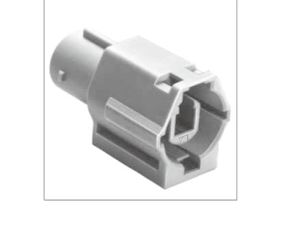
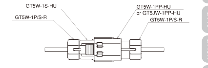
GT5W-1S-HU 755-0027-2 PBT Light Gray 1 YES

Note : Use correct retainer.

Retainer ( Used with GT5W-1PP-HU, GT5JW-1PP-HU, GT5W-1S-HU and GT5W-1P-HU)

PDF page 16 diagram
PDF page 16 diagram
Part No. HRS No. Material/Plating or Color Packaging RoHS
GT5W-1P/S-R 755-0028-5 Retainer:PBT/Dark Gray Rubber:Silicon rubber Compound/Light Blue 1 YES
PDF page 16 diagram

Note : Outer diameter of the cable must be within Ø2.9 to Ø3.4 mm.

\*Waterproofness will depend on the cable. Please contact a Hirose Electric sales representative for further infomation when using this product

Page 17

M Connectors

PDF page 17 diagram

Housing

PDF page 17 diagram
Part No. HRS No. Material/Plating or Color Packaging Ro
GT5W-1P-HU 755-0026-0 Housing:PBT/Light Gray Connector seal:Silicon rubber Compound/White 1 YE

YES

Note : Use correct retainer.

PDF page 17 diagram
PDF page 17 diagram

BRecommended Bracket Dimensions Diagram

(Used with GT5W-1PP-HU)

BMated condition (mounted)

Please check elsewhere for information about the bracket for GT5JW-1PP-HU.

PDF page 17 diagram
PDF page 17 diagram
PDF page 17 diagram
PDF page 17 diagram
Part No. HRS No. Material/Plating or Color Packaging Ro
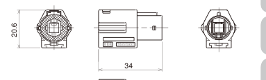
GT5W-1PP-HU 755-0070-1 Housing:PBT/Light Gray Connector seal:Silicon rubber Compound/White 1 YE
GT5JW-1PP-HU 755-0069-2

YES

Note : Use correct retainer.

Page 18

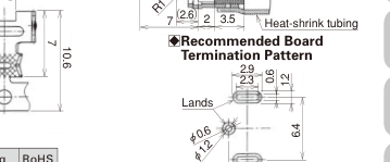
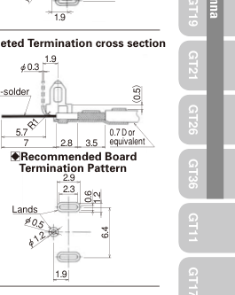
G Terminals

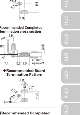
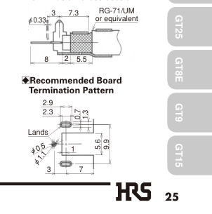
BRecommended Completed

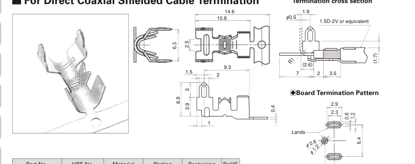
For Direct Coaxial Shielded Cable Termination

Termination cross section

PDF page 18 diagram
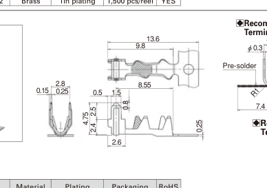
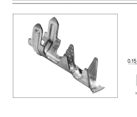
Part No. HRS No. Material Plating P ackaging R oHS
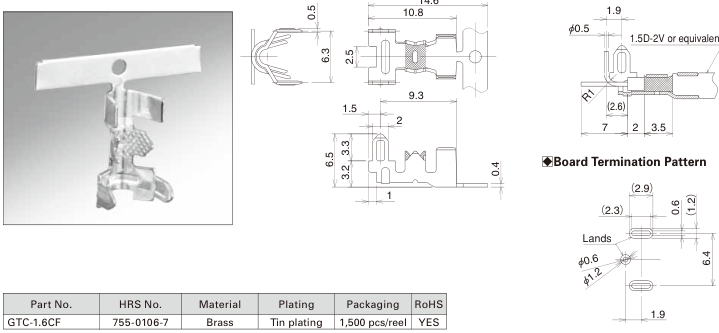
GTA-1.6CF(70) 755-0032-2 70 Brass Tin plating 1,5 00 pcs/reel Y ES

1.9

PDF page 18 diagram
PDF page 18 diagram

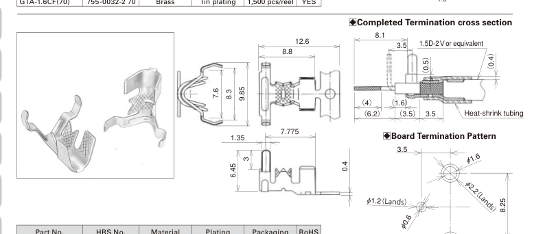
BCompleted Termination cross section

14.6

PDF page 18 diagram

Page 19

PDF page 19 diagram
PDF page 19 diagram

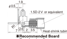
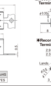
BCompleted Termination cross section

PDF page 19 diagram
PDF page 19 diagram
Part No. HRS No. Material Plating Packaging RoHS
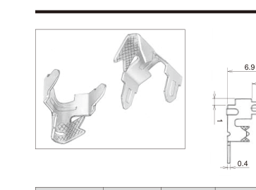
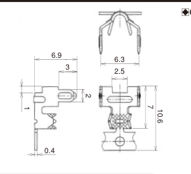
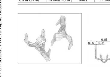
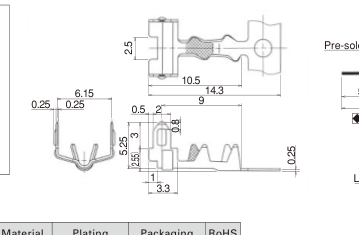
G-1.6PCF(70) 755-0029-8 70 Brass Tin plating 1,500 pcs/reel YES
PDF page 19 diagram
PDF page 19 diagram
PDF page 19 diagram
PDF page 19 diagram
Part No. HRS No. Material Plating Packaging RoHS
GTA-0.7CF 755-0074-2 Brass Tin plating 1,500 pcs/reel YES
PDF page 19 diagram
PDF page 19 diagram
Part No. HRS No. Material Plating Packaging RoHS
GTB-0.7CF 755-0075-5 Brass Tin plating 1,500 pcs/reel YES
PDF page 19 diagram
21.3 14.8 9.9 2.5 13.3 2 3 2.9 6.3 2.3 0.7 1.3 1 ands
Part No. HRS No. Material Plating Packaging RoHS
GTE-3.7CF 755-0122-3 Brass Tin plating 1,100 pcs/reel YES
PDF page 19 diagram

Termination cross section

PDF page 19 diagram

Page 20

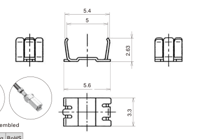
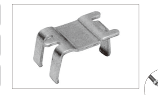
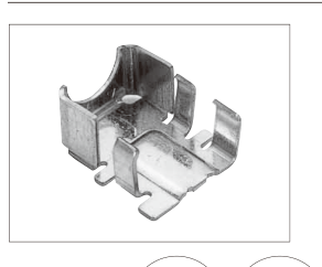
Bottom Shield cover

PDF page 20 diagram
PDF page 20 diagram

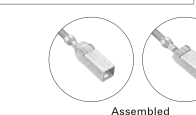
Assembled

Part No. HRS No. Material Plating Packaging RoHS
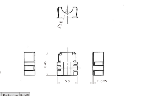
GT5-1P/S-CSB(70) 755-0048-2 70 Brass Tin plating 1 YES
PDF page 20 diagram
PDF page 20 diagram
PDF page 20 diagram
Part No. HRS No. Material Plating Packaging RoHS
GT5C-1P-CSB(70) 755-0088-7 70 Brass Tin plating 1 YES

Page 21

PDF page 21 diagram

Panel Mounting In-line Bracket

PDF page 21 diagram
Part No. HRS No. Material Plating Used with connectors Packaging RoHS
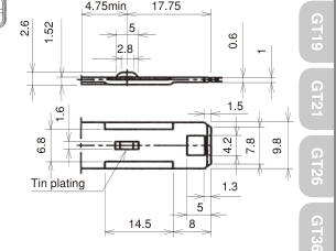
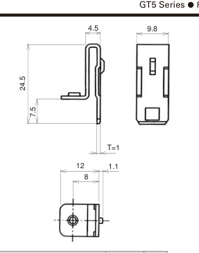
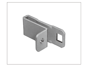
GT-BK(70) 751-0039-6 70 SPCC Tin plating GT5-1PP-HU(70), GT5-1PP-HU(A)(70), GT5-1PP-HU(B)(70) GT5-1PP-HU(C)(70), GT5-1PP-HU(D)(70) GT5-1PP-HU(E)(70), GT5-1PP-HU(F)(70) GT5-1PP-HU(G)(70), GT5-1PP-HU(H)(70) GT5-2/1PP-HU(70), GT5-2PP-HU(70) GT5-2PP-HU(A)(70), GT5-2PP-HU(B)(70) GT5-2PP-HU(C)(70) 1 YES

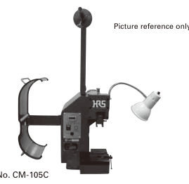
B Crimping tools

User's manuals are available. Please ask your Hirose Electric account representative.

Automatic crimping machine

PDF page 21 diagram

Specifications

Item Specification Remarks
Press capacity 1.5tons
Stroke length 30mm
Number of strokes 200spm(50Hz) 200spm(60Hz)
Weight 75kg
Motor 0.2kW AC100V
Crimping speed 2000 to 4000pcs/hour

\* Crimp height setting tables are available for each cable type. Please contact your nearest Hirose Electric account representative. Different cables will require different crimp height settings.

Page 22

Harness tools

Terminal Product No. Terminal HRS No. Tool No. Tool HRS No.
GT5-30/0.7-1.5PCF(70) 755-0017-9 70 AP105-GT5-30/0.7-1.5P 901-5021-8
GT5-30/0.7-1.5SCF(70) 755-0065-1 70 AP105-GT5-30/0.7-1.5S 901-5080-7
GT5L-2428/1.6-2.5PCF(70) 755-0079-6 70 AP105-GT5-2428/1.6-2.5P 901-5100-2
GT5-2428/1.6-2.5SCF(70) 755-0078-3 70 AP105-GT5-2428/1.6-2.5S 901-5101-5
GT5-30/1.6-2.9PCF(70) 755-0021-6 70 AP105-GT5-30/1.6-2.9P-ID 901-5019-6
AP105-GT5-30/1.6-2.9P 901-5017-0
GT5-30/1.6-2.9SCF(70) 755-0022-9 70 AP105-GT5-30/1.6-2.9S-ID 901-5020-5
AP105-GT5-30/1.6-2.9S 901-5018-3
GT5-2428/1.6-2.9PCF(70) 755-0001-9 70 AP105-GT5-2428/1.6-2.9P 901-5029-0
AP105-GT5-2428/1.6-2.9PWS 901-5031-1
AP105-GT5-2428/1.6-2.9P-B 901-5103-0
GT5-2428/1.6-2.9SCF(70) 755-0002-1 70 AP105-GT5-2428/1.6-2.9S 901-5030-9
AP105-GT5-2428/1.6-2.9SWS 901-5032-4
AP105-GT5-2428/1.6-2.9S-B 901-5104-3
GT5-2022/1.6-2.9SCF(70) 755-0071-4 70 AP105-GT5-2022/1.6-2.9S 901-5088-9
GT5-2022/F2.7-3.5PCF(70) 755-0076-8 70 AP105-GT5-2022/F2.7-3.5P 901-5091-3
GT5-2022/F2.7-3.5SCF(70) 755-0077-0 70 AP105-GT5-2022/F2.7-3.5S 901-5092-6
GT5-2022/F3.3-3.8PCF(70) 755-0053-2 70 AP105-GT5-2022/F3.3-3.8P 901-5075-7
GT5-2022/F3.3-3.8SCF(70) 755-0054-5 70 AP105-GT5-2022/F3.3-3.8S 901-5076-0
GT5-2022/F3.3-5PCF(70) 755-0033-5 70 AP105-GT5-2022/F3.3-5P-ID 901-5058-8
AP105-GT5-2022/F3.3-5P 901-5059-0
GT5-2022/F3.3-5SCF(70) 755-0034-8 70 AP105-GT5-2022/F3.3-5S-ID 901-5060-0
AP105-GT5-2022/F3.3-5S 901-5061-2
GT5-30/F4-5PCF(70) 755-0019-4 70 AP105-GT5-30/F4-5P-ID 901-5033-7
GT5-30/F4-5SCF(70) 755-0020-3 70 AP105-GT5-30/F4-5S-ID 901-5034-0
GT5-2428/F4-5PCF(70) 755-0023-1 70 AP105-GT5-2428/F4-5P-ID 901-5035-2
AP105-GT5-2428/F4-5P-3C2V 901-5056-2
GT5-2428/F4-5SCF(70) 755-0024-4 70 AP105-GT5-2428/F4-5S-ID 901-5036-5
AP105-GT5-2428/F4-5S-3C2V 901-5057-5
GT5-2022/F4-5PCF(70) 755-0035-0 70 AP105-GT5-2022/F4-5P 901-5052-1
AP105-GT5-2022/F4-5P-18ID 901-5121-2
GT5-2022/F4-5SCF(70) 755-0036-3 70 AP105-GT5-2022/F4-5S 901-5053-4
AP105-GT5-2022/F4-5S-18ID 901-5102-8
G-1.6PCF(70) 755-0029-8 70 AP105-G-1.6P 901-5041-5
GTA-0.7CF 755-0074-2 AP105-GTA.B-0.7P 901-5141-0
GTB-0.7CF 755-0075-5 AP105-GTA.B-0.7P 901-5141-0
GTA-1.6CF(70) 755-0032-2 70 AP105-GTA.B-1.6P 901-5047-1
GTB-1.6CF(70) 755-0049-5 70 AP105-GTA.B-1.6P 901-5047-1
GTC-1.6CF 755-0106-7 AP105-GTA.B-1.6P 901-5047-1
GTE-3.7CF 755-0122-3 AP105-GTE-3.7 901-5151-3