
GFMQ_15 VISHAY
Document overview
- Manufacturer or author: Provided By www.digicamel.com(FREE DATASHEET DOWNLOAD SITE)
- PDF pages: 3
Technical content
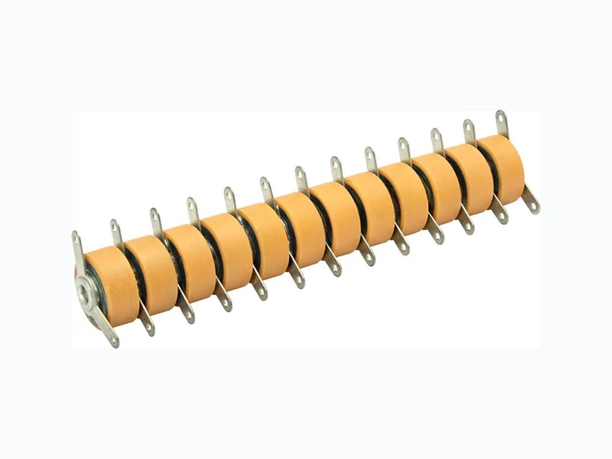
GFMQ, GFWQ www.vishay.com Vishay Draloric Revision: 11-Sep-15 1 Document Number: 22034 For technical questions, contact: cdc@vishay.com THIS DOCUMENT IS SUBJECT TO CHANGE WITHOUT NOTICE. THE PRODUCTS DESCRIBED HEREIN AND THIS DOCUMENT ARE SUBJECT TO SPECIFIC DISCLAIMERS, SET FORTH AT www.vishay.com/doc?91000 High Voltage Ceramic Capacitor Stacks, with Solder Tags, Class 2 Ceramic MATERIAL Capacitor elements made from class 2 ceramic dielectric with noble metal electrodes. Connection terminals between the discs: brass, silver plated OPTIONAL TERMINALS We offer a variety of intermed iate solder tags to meet customers requirements. Please contact us.
FEATURES
- Small size
- Multiple design up to 12 stages
- Voltage rating of the individual discs 8 kV DC
- Other versions on request
APPLICATIONS
Ceramic capacitor stacks have been developed for use in low power voltage multipliers used in high voltage DC generators. The major applications are x-ray equipment for medical diagnostics or elec trostatic paint spraying equipment. CAPACITANCE RANGE 370 pF to 500 pF CAPACITANCE TOLERANCE ± 20 % CERAMIC DIELECTRIC R2005 (X7R) RATED VOLTAGE 8.0 kVDC per single disc DIELECTRIC STRENGTH TEST 13 kVDC per single disc, in dielectric fluid DISSIPATION FACTOR Max. 2.5 % (1 kHz) INSULATION RESISTANCE Min. 10 G (at 25 °C) OPERATING TEMPERATURE RANGE -25 °C to +85 °C QUICK REFERENCE DATA DESCRIPTION VALUE Ceramic Class 2 Ceramic Dielectric R2005 Type GFMQ10.., GFWQ10.. GFMQ12.., GFWQ12.. Voltage (V DC) 8000 Min. Capacitance (pF) 370 500 Max. Capacitance (pF) 370 500 Mounting Solder tags
GFMQ, GFWQ www.vishay.com Vishay Draloric Revision: 11-Sep-15 2 Document Number: 22034 For technical questions, contact: cdc@vishay.com THIS DOCUMENT IS SUBJECT TO CHANGE WITHOUT NOTICE. THE PRODUCTS DESCRIBED HEREIN AND THIS DOCUMENT ARE SUBJECT TO SPECIFIC DISCLAIMERS, SET FORTH AT www.vishay.com/doc?91000 Notes (1) Per single disc (2) In an insulating environment (3) Min. 3 s in dielectric fluid SAP PART NUMBER AND ELECTRICAL DATA PART NUMBER CERAMIC CAPACITANCE VALUES (1) (pF) RATED VOLTAGE (1)(2) (kVDC) TEST VOLTAGE (1)(3) (kVDC) NO. OF DISC IN SERIES LMAX. mm (INCH) D mm (INCH) TYPE GFMQ10.. RHS370P38BPZHA6000 R2005 (X7R) 370 (± 20 %) 8.0 13 (0.413 ± 0.012)RHS370P38BPZHB6001 12 73.5 (2.893) TYPE GFWQ10.. RHS370P38BPZHC6002 R2005 (X7R) 370 (± 20 %) 8.0 13 (0.413 ± 0.012)RHS370P38BPZHD6003 12 73.5 (2.893) TYPE GFMQ12.. RHS500P38BPZHE6004 R2005 (X7R) 500 (± 20 %) 8.0 13 8 49.5 (1.949) 12.0 ± 0.2 (0.472 ± 0.008)RHS500P38BPZHF6005 10 61.5 (2.421) RHS500P38BPZHG6006 12 73.5 (2.893) TYPE GFWQ12.. RHS500P38BPZHH6007 R2005 (X7R) 500 (± 20 %) 8.0 13 8 49.5 (1.949) 12.0 ± 0.2 (0.472 ± 0.008)RHS500P38BPZHJ6008 10 61.5 (2.421) RHS500P38BPZHK6009 12 73.5 (2.893) DIMENSIONS DATA RELATED DOCUMENTS General Information www.vishay.com/doc?22090 0.3 (0.012) TYPE GFMQ 18 (0.71) 1.5 (0.059) 3.2 (0.126) L D 0.3 (0.012) Ø 1 (0.04 Dia.) 8.5 (0.335) 140°TYPE GFWQ L D
www.vishay.com Vishay Revision: 08-Feb-17 1 Document Number: 91000 Disclaimer ALL PRODUCT, PRODUCT SPECIFICATIONS AND DATA AR E SUBJECT TO CHANGE WITH OUT NOTICE TO IMPROVE RELIABILITY, FUNCTION OR DESIGN OR OTHERWISE. Vishay Intertechnology, Inc., its affiliates, agents, and employee s, and all persons acting on it s or their behalf (collectivel y, “Vishay”), disclaim any and all liability for any errors, inaccuracies or incompleteness contained in any datasheet or in any other disclosure relating to any product. Vishay makes no warranty, representation or guarantee regarding the suitability of th e products for any particular purpose or the continuing production of any product. To the maximum extent permitted by applicable law, Vishay disclaims (i) any and all liability arising out of the application or use of any product , (ii) any and all liability, including without limitation specia l, consequential or incidental damages, and (iii) any and all implied warranties, includ ing warranties of fitness for particular purpose, non-infringement and merchantability. Statements regarding the suitability of products for certain types of applicatio ns are based on Vishay’s knowledge of typical requirements that are often placed on Vishay products in generic applications. Such statements are not binding statements about the suitability of products for a particular applic ation. It is the customer’s responsibility to validate tha t a particular product with the prope rties described in the product sp ecification is suitable for use in a particular application. Parameters provided in datasheets and / or specifications may vary in different ap plications and performance may vary over time. All operating parameters, including typical parameters, must be validated for each customer application by the customer’s technical experts. Product specifications do not expand or otherwise modify Vishay’s term s and conditions of purchase, including but not limited to the warranty expressed therein. Except as expressly indicated in writing, Vishay products are not designed for use in medical, life-saving, or life-sustaining applications or for any other application in which the failure of the Vishay product could result in personal injury or death. Customers using or selling Vishay product s not expressly indicated for use in such applications do so at their own risk. Please contact authorized Vishay personnel to obtain writ ten terms and conditions rega rding products designed for such applications. No license, express or implied, by estoppel or otherwise, to any intellectual property rights is gran ted by this document or by any conduct of Vishay. Product names and markings noted herein may be trademarks of their respective owners. © 2017 VISHAY INTERTECHNOLOGY, INC. ALL RIGHTS RESERVED