


 Download PDF
GF9103 GENNUM
Document overview
- PDF pages: 9
Technical content
Page 1

FEATURES
- 4:2:2 to over-sampled RGB or YCBCR conversion in a single device
- single 10 bit 4:2:2 input
- internal 4:2:2 de-multiplexer
- 4:2:2 to 8:8:8 interpolation filters
- internal YCBCR to RGB color space conversion
- optional YCBCR (8:8:8) output mode
- setup insertion in Luminance channel under user control
- user selectable digital SIN X/X correction
- rounding to 10/8 bit resolution per output channel
- 40 MHz maximum clock rate
- single +5 V power supply
APPLICATIONS
- Over-Sampling 4:2:2 to Analog RGB Conversions for video monitoring
- Over-Sampling 4:2:2 to Analog YCBCR Conversions for video monitoring
ORDERING INFORMATION
| PART NUMBER | PACKAGE | TEMPERATURE RANGE |
|---|---|---|
| GF9103-CPS | 68 pin PLCC | 0° to 70° C |
| GF9103-CTS | 68 pin PLCC Tape | 0° to 70° C |
MultiGEN ™ GF9103 Over-Sampling
Color Space Converter for Video
Monitoring
DATA SHEET
DEVICE DESCRIPTION
The GF9103 is specifically designed to simplify conversions from 4:2:2 component digital video to analog RGB or analog YCBCR component video. The GF9103 simplifies this process by performing 4:2:2 to 8:8:8 interpolation, digital color space conversion and digital SIN X/X correction in a single device. Immediately following the GF9103, three over-sampled channels of RGB or YCBCR data may be passed through Digital to Analog converters and simplified analog reconstruction filters.
The GF9103 accepts a single 10 bit stream of 4:2:2 data and internally de-multiplexes it into three 10 bit channels of YCBCR data. The YCBCR data is then passed through three linear phase FIR filters that over-sample the Y data by a factor of 2 and the CBand CR data by a factor of 4.
While operating in an over-sampled RGB output mode, the interpolated YCBCR data is passed through the internal color space converter to convert the YCBCR data to RGB data according to CCIR-601. Alternatively, the color space converter may be bypassed to obtain over-sampled YCBCR (8:8:8) output data. While operating in YCBCR output mode, setup may be dynamically inserted into the Luminance channel.
Prior to output rounding, over-sampled YCBCR or RGB data may be corrected for SIN X/X characteristics of D/A conversion. Output data may be rounded to 10 or 8 bit resolution per channel. CB and CR may be presented as signed or unsigned data.
The GF9103 is packaged in a 68 pin PLCC package, operates with a single +5 V power supply and typically consumes only 85 mA of current when operated at 27 MHz.
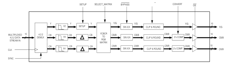
FUNCTIONAL BLOCK DIAGRAM
Revision Date: August 1997
Document No. 521 - 33 - 04
GENNUM CORPORATION P.O. Box 489, Stn. A, Burlington, Ontario, Canada L7R 3Y3 Tel. +1 (905) 632-2996 Fax. +1 (905) 632-5946 E-mail: info@gennum.com
www.gennum.com
Page 2
PIN DESCRIPTION
| PIN NO. | SYMBOL | DESCRIPTION |
|---|---|---|
| 10, 18, 27, 36, 44, 52, 61, 68 | V DD | ±5 V ± 5% power supply. |
| 1, 6, 7, 9, 26, 30, 35, 40, 43, 60, 64 | GND | Ground. |
| 3 | SCAN_EN | Set Low. |
| 8, 11-17, 19, 20 | SI 9..0 | Input Data Port: Input data port with internal pull-downs. Input data is assumed to be a multiplexed stream of C YC [Y] C ..., where [Y] denotes an isolated Luminance sample. B R B SI is the Most Significant Bit and SI is the Least Significant Bit. 9 0 |
| 4 | OE | Output Enable: Active low input with internal pull-up. When OE is high, the output data ports are in high impedance state. |
| 59-53, 51-49 | SOA 9..0 | Output Data Port A: Depending on device configuration, SOA may output over-sampled 9..0 Y or G video. SOA is the Most Significant Bit and SOA is the Least Significant Bit. 9 0 |
| 48-45, 42, 41, 39-37, 34 | SOB 9..0 | Output Data Port B: Depending on device configuration, SOB may output over-sampled 9..0 C or B video. SOB is the Most Significant Bit and SOB is the Least Significant Bit. B 9 0 |
| 33-31, 29, 28, 25-21 | SOC 9..0 | Output Data Port C: Depending on device configuration, SOC may output over-sampled 9..0 C or R video. SOC is the Most Significant Bit and SOC is the Least Significant Bit. R 9 0 |
| 2 | CLK | System Clock: All timing information relative to rising edge of clock. |
| 5 | SYNC | Synchronization: Control signal input with internal pull-up. This input is used to synchronize the incoming data by holding SYNC high on clock period N and low on clock period N+1 when the first C sample is presented to the SI inputs. SYNC may be held low until re- B 9..0 synchronization is desired or may be toggled at every occurrence of a C sample. B |
| 65 | SELECT_MATRIX | Select Color Space Conversion: Control signal input with internal pull-down. SELECT_MATRIX is used to enable and disable the internal YC C to RGB color space B R converter. Color space conversion is enabled while SELECT_MATRIX is high and is disabled while SELECT_MATRIX is low. |
| 66 | BYPASS | Bypass SIN X/X Correction: Control signal input with internal pull-up. When BYPASS is high, SIN X/X correction for the three output channels is enabled. While BYPASS is low, SIN X/X correction is by-passed. |
| 63 | SETUP | Setup: Control signal input with internal pull-down. SETUP is used to enable and disable setup insertion in the Luminance channel. |
| 62 | CONVERT | Two's Complement Conversion: Control signal input with internal pull-up. While CONVERT is high, SOB and SOC output signed (two’s complement) digital data. While 9..0 9..0 CONVERT is low, SOB and SOC output unsigned (offset binary) data. When 9..0 9..0 operating in RGB output mode, the CONVERT pin is over-ridden and both SOB and 9..0 SOC output unsigned digital data. SOA outputs unsigned digital data in all operating 9..0 9..0 modes. |
| 67 | RND10/8 | Output Rounding: Control signal input with internal pull-up. RND10/8 selects rounding to 10 bit resolution per channel when high and rounding to 8 bit resolution per channel when low. |
Page 3
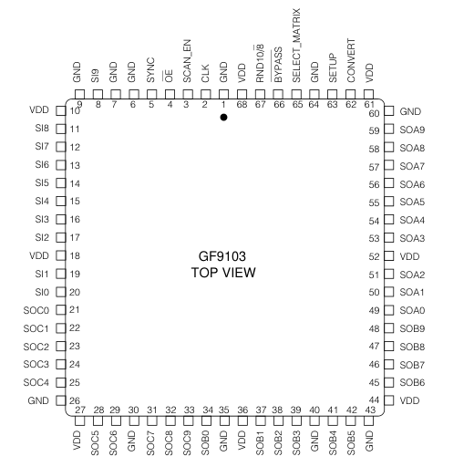
Fig. 1 GF9103 Pin Connections
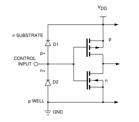
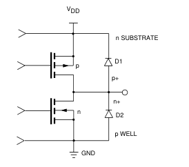
Fig. 2a Equivalent Input Circuit
Fig. 2b Equivalent Output Circuit
Page 4
DEVICE DESCRIPTION
The GF9103 is composed of five main sections:
- 4:2:2 De-Multiplexer 2. FIR Filtering and Setup Insertion 3. Color Space Conversion 4. Digital SIN X/X Correction 5. Output Processing
4:2:2 DE-MULTIPLEXER
The de-multiplexer accepts data multiplexed in a SMPTE 125M compliant format from the SI9..0 input data port. SI9 is the Most Significant Bit and SI0 is the Least Significant Bit. The input data stream is assumed to be a multiplexed stream of CB Y CR [Y] CB..., where the three words CB Y CR refer to cosited samples and where [Y] refers to an isolated Luminance sample. When operating the GF9103 with 8 bit input data, SI9..2 should be used to present data to the device and SI1..0 should be set low.
At least once during a power cycle, the GF9103 must be synchronized to the incoming data stream. The GF9103 is synchronized by holding SYNC high on clock period N and low on clock period N+1 when the first CB sample is presented to the SI9..0 inputs. SYNC may be held low until re-synchronization is desired, or it may be toggled at every occurrence of a CB sample. Refer to the timing diagram in Figure 9 for required operation of the SYNC control signal.
The internal de-multiplexer will de-multiplex all data in the input data stream including any ancillary, EDH,VITC, and EAV/SAV ... signals that may be present. Since this data is passed directly to the interpolation filters in the same way that active video would be, it is recommended that such data be replaced with appropriate blanking levels prior to entering the GF9103.
The output of the 4:2:2 de-multiplexer consists of three 10 bit channels of YCBCR data. All three channels are then fed to their respective interpolation filter.
INTERPOLATION FILTERS
Within the interpolation stage, the Luminance data is oversampled by a factor of two and the CB and CR data is oversampled by a factor of four so that the 4:2:2 data is converted to 8:8:8 data. By over-sampling the 4:2:2 data to 8:8:8 data, the size, cost and complexity of the analog reconstruction filters following Digital to Analog converters are reduced.
The Luminance data is over-sampled by a linear phase FIR filter providing 0.0 dB DC gain, +0.038/-0.025 pass- band ripple [0.0 ƒs to 0.21 ƒs], 6 dB attenuation at ƒs/4, and 47 dB stopband attenuation [0.30 ƒs to 0.50 ƒs]. Figure 3 and Figure 4 present the frequency response of the Luminance interpolation filter.
The CB and CR data is over-sampled by a linear phase FIR filter providing 0.0 dB DC gain, passband ripple of +0.2 dB/- 0.2 dB [0.0 to 0.07 ƒs], 6 dB attenuation at ƒs/8 and a stopband attenuation of 28 dB [ 0.17ƒs to 0.50 ƒs].
Figure 5 and Figure 6 present the frequency response of the CB and CR interpolation filters.
Following the interpolation process, a DC offset may be introduced into the Luminance channel. Setup insertion is enabled and disabled by the SETUP control signal. While SETUP is high, the Luminance data is scaled by a factor of +947/1024 and an offset of +71 (decimal) is added. While SETUP is low, no scaling or offset is applied and the data passes through the stage unmodified. The timing diagram in Figure 10 demonstrates the operation of the SETUP control signal.
COLOR SPACE CONVERSION
Two operating modes exist for the color space converter section. These two modes are controlled by the SELECT_MATRIX control signal. While SELECT_MATRIX is low, the de-matrixing 3 x 3 multiplier is bypassed so that over-sampled Y CB CR data is passed through the stage unmodified. While SELECT_MATRIX is high, the 3 x 3 multiplier implements the following color space conversion:
Y
G 1 -689/2048 -1430/2048 =
CB
B 1 3548/2048
0
R 1 0 2807/2048
CR
SIN X/X CORRECTION
While BYPASS is high, SIN X/X correction is enabled on each of the three output channels. SIN X/X correction is implemented by passing the data through a FIR filter with the frequency response shown in Figure 7. While BYPASS is low, the FIR filter is bypassed and each channel is passed directly to the output processing section. Total latency through the device is 22 clock cycles when BYPASS is low and 24 clock cycles when BYPASS is high.
OUTPUT PROCESSING
Output data may be rounded to 10 or 8 bit accuracy. RND10/8 should be set high for 10 bit output rounding and set low for 8 bit output rounding. Rounding to 8 bit accuracy is accomplished by adding a rounding bit to SO1 and then zeroing both SO0 and SO1.
CB and CR data may be output as signed (two’s complement) or unsigned (offset binary) data depending on the state of the CONVERT control signal. When CONVERT is set high, the CB and CR channels are output as signed (two’s complement) data. When CONVERT is set low, CB and CR are output as unsigned (offset binary) data, obtained by inverting the sign bit of the two's complement number. When operating in RGB output mode, the CONVERT pin is over-ridden and RGB data is always output as unsigned (offset binary) data.
Page 5
CONTROL SIGNAL/OPERATING MODE SUMMARY
SYNC
The SYNC control signal provides synchronization for the internal 4:2:2 de-multiplexer. SYNC should be held high on clock period N and low on clock period N+1 when the first CB sample is presented to the SI9..0 inputs. SYNC may be held low until re-synchronization is desired or may be toggled at every occurrence of a CB sample.
SELECT_MATRIX AND SETUP
SELECT_MATRIX and SETUP select the color space conversion and offset insertions which the GF9103 is to perform. The following chart presents the available color space conversions and the corresponding states of the SELECT_MATRIX and SETUP control pins. SETUP is a dynamic pin that may be modified every clock cycle.
| SELECT_MATRIX | SETUP | DESCRIPTION |
|---|---|---|
| 0 | 0 | Selects output to be over-sampled YC C with no setup in Y channel. B R |
| 0 | 1 | Selects output to be over-sampled YC C with a scaling factor of B R +947/1024 and an offset of +71 (decimal) applied to the Y channel. |
| 1 | X | Selects output to be over-sampled RGB with no setup. |
SIN X/X CORRECTION
| BYPASS | DESCRIPTION |
|---|---|
| 1 | SIN X/X correction enabled on all output data channels. Latency through the device is 24 clock cycles. |
| 0 | SIN X/X correction disabled. Latency through the device is 22 clock cycles. |
OUTPUT ROUNDING
| RND10/8 | DESCRIPTION |
|---|---|
| 1 | Output data rounded to 10 bit resolution per channel. |
| 0 | Output data rounded to 8 bit resolution per channel. |
TWO’S COMPLEMENT OUTPUT CONVERSION
| CONVERT | SELECT_MATRIX | DESCRIPTION |
|---|---|---|
| 1 | 0 | SOB and SOC output signed (two's complement) C and C data. 9..0 9..0 B R |
| 0 | 0 | SOB and SOC output unsigned (offset binary) C and C data. 9..0 9..0 B R |
| X | 1 | SOB and SOC output unsigned B and R data. 9..0 9..0 |
OUTPUT ENABLE
| OE | DESCRIPTION |
|---|---|
| 0 | All output data ports are enabled. |
| 1 | All output data ports are in high impedance state. |
Page 6
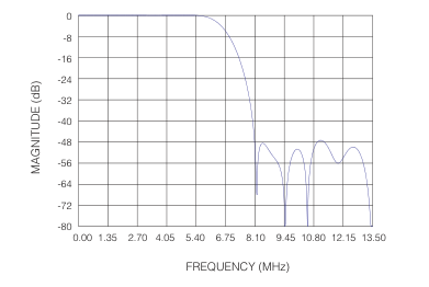
Fig. 3 Frequency Response of Luminance Interpolation Filter (Sampling at ƒs=27MHz)
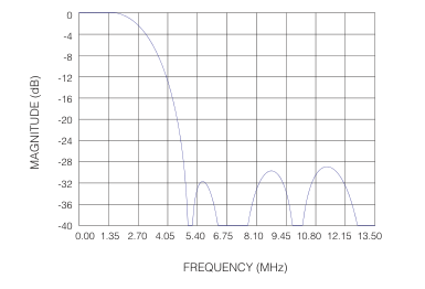
Fig. 5 Frequency Response of Chrominance Interpolation Filter (Sampling at ƒs=27MHz)
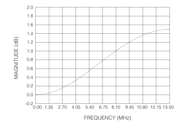
Fig. 7 SIN X/X Compensation Filter Frequency Response (Sampling at ƒs=27MHz)
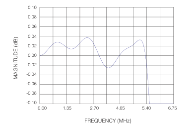
Fig. 4 Frequency Response of Luminance Interpolation Filter (Sampling at ƒs=27MHz)
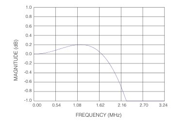
Fig. 6 Frequency Response of Chrominance Interpolation Filter (Sampling at ƒs=27MHz)
| PARAMETER | LUMINANC FILTER | E CHROMINANCE FILTER |
|---|---|---|
| Filter Order | 31 | 15 |
| Pass Band Ripple | +0.038 / -0.025 (0.0 ƒs to 0.21 | dB +0.2 / -0.2 dB ƒs) (0.0 ƒs to 0.21 ƒs) |
| DC Gain | 0.0 dB | 0.0 dB |
| Attenuation | -6.00 dB (at ƒ | /4) -6.00 dB (at ƒ /8) S S |
| Stop Band Attenuation | -47 dB (0.30 ƒs to 0.50 | -28 dB ƒs) (0.17 ƒs to 0.50 ƒs) |
fig. 8 luminance and chrominance filter characteristics
Page 7
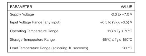
ABSOLUTE MAXIMUM RATINGS
ELECTRICAL CHARACTERISTICS
VDD = 5V, TA = 0°C, RL = 150 Ω to GND and 144 Ω AC coupled unless otherwise shown.
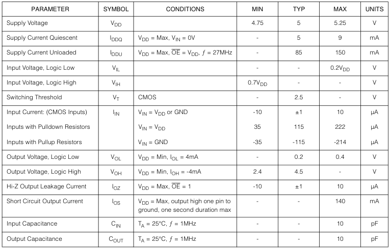
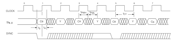
Fig. 9 Operation of SYNC Control Signal
Page 8
SWITCHING CHARACTERISTICS
TA from 0°C to 70°C unless otherwise specified.
| NAME | PARAMETER | TEST CONDITIONS | MIN | TYP | MAX | UNITS |
|---|---|---|---|---|---|---|
| t D | Output delay | V = Min, C = 25pF DD L | 8 | 9 | 10 | ns |
| t OH | Output hold time | V = Max, C = 25pF DD L | 1 | - | - | ns |
| t EN | Output enable | V = Min, C = 25pF DD L | - | - | 8 | ns |
| t DIS | Output disable | V = Min, C = 25pF DD L | - | - | 8 | ns |
| t CY | Cycle time | 25 | - | - | ns | |
| t PWL | Clock pulse width low | 10 | - | - | ns | |
| t PWH | Clock pulse width high | 10 | - | - | ns | |
| t S | Input setup time | 8 | - | - | ns | |
| t H | Input hold time | 1 | - | - | ns |
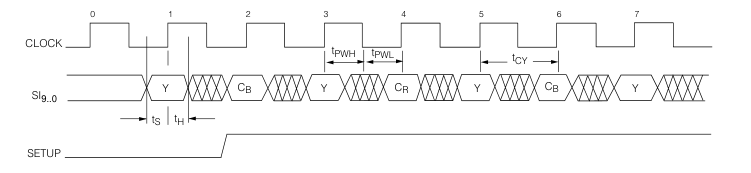
Fig. 10 Operation of SETUP Control Signal
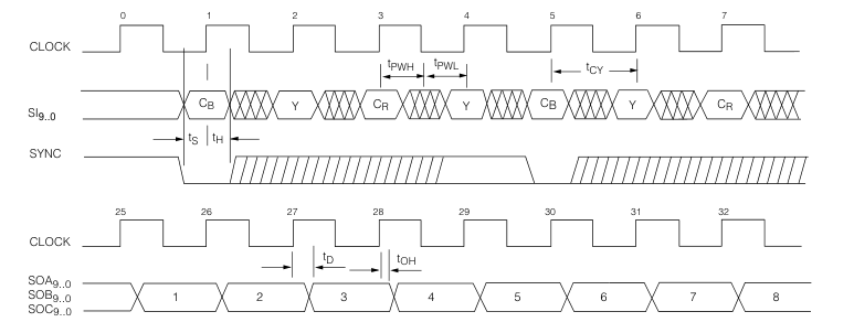
Fig. 11 Input/Output Timing, BYPASS = 1
Page 9
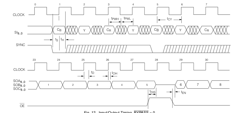
Fig. 12 Input/Output Timing, BYPASS = 0
GENNUM CORPORATION
MAILING ADDRESS: P.O. Box 489, Stn. A, Burlington, Ontario, Canada L7R 3Y3 Tel. +1 (905) 632-2996 Fax. +1 (905) 632-5946
SHIPPING ADDRESS: 970 Fraser Drive, Burlington, Ontario, Canada L7L 5P5
GENNUM JAPAN CORPORATION C-101, Miyamae Village, 2-10-42 Miyamae, Suginami-ku Tokyo 168-0081, Japan Tel. +81 (03) 3334-7700 Fax. +81 (03) 3247-8839
GENNUM UK LIMITED Centaur House, Ancells Bus. Park, Ancells Rd, Fleet, Hants, England GU13 8UJ Tel. +44 (0)1252 761 039 Fax +44 (0)1252 761 114
Gennum Corporation assumes no responsibility for the use of any circuits described herein and makes no representations that they are free from patent infringement.
© Copyright March 1995 Gennum Corporation. All rights reserved. Printed in Canada.