

 Download PDF
DATASHEET SEARCH SITE
Document overview
- PDF pages: 4
Technical content
Page 1
Type GC11
GC14, GC16
Thermometrics Glass Encapsulated NTC Chip Thermistor
Description
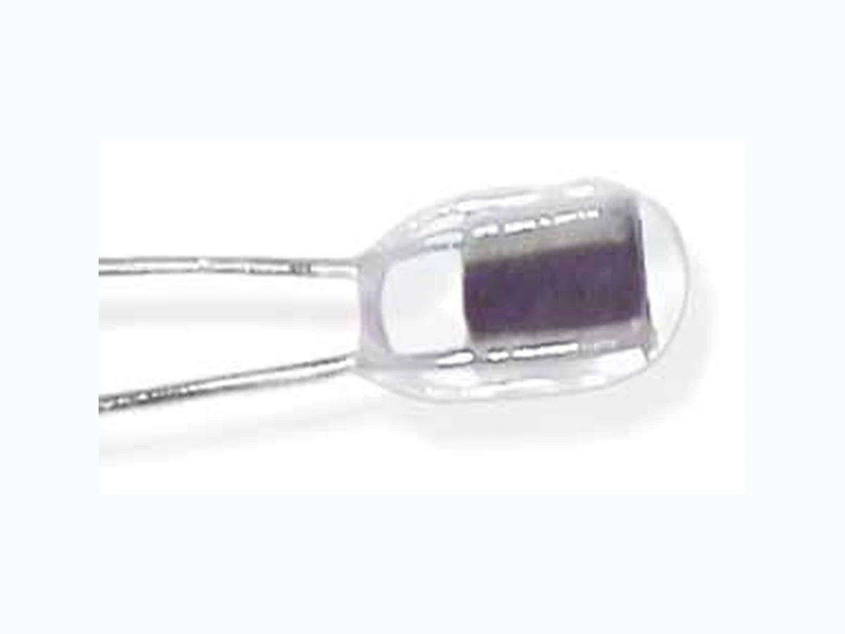
Small glass encapsulated chip thermistors on fine diameter platinum alloy lead wires.
Features
- Glass encapsulated bead thermistors.
- Suitable for temperature measurement, control or compensation applications.
- Fast thermal response times.
- Suitable for self-heated applications such as liquid level sensing or gas flow measurement.
- Operating temperatures range from -40°C to +250°C.
- Unaffected by severe environmental exposures, including nuclear radiation.
- Intermittent operation up to 450°C is permissible; however, stability will be degraded.
- Improved beta tolerance with respect to glass encapsulated beads.
- RoHS compliant to 2002/95/CE.
Amphenol
Advanced Sensors
Options
- Non-standard resistance tolerances and values
- Reference temperature(s) other than 25°C - specify.
- Custom packaging available.
- Welded or soldered extension leads - specify lead material, diameter, length and insulation, if any.
- Calibration - specify temperature(s).
- Interchangeable pairs or sets, curve matching — specify temperature ranges and tolerance(s).
- Special aging and conditioning for high reliability applications.
Page 2
Specifications
Thermal and Electrical Properties
Note: These thermal and electrical properties are for all small glass encapsulated thermistors. All definitions and test methods are per MIL-PRF-23648.
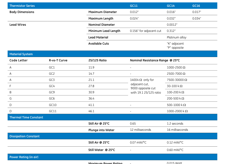
Maximum Power Rating
-
0.015 Watt
100% Maximum Power to: -
75 °C
Derated to 0% at
-
250 °C
Resistance-Vs.-Temperature Characteristics
The nominal resistance range for the zero-power resistance at 25°C is shown for each available Material System. Each Material System is denoted by an ordering Code Letter, a referenced curve number and the
nominal 25°C/125°C resistance ratio. The R-vs.-T curves are on the facing page.
Standard Tolerances
Tolerance Code Letter
G J K L M N S
±% Tolerance at 25 °C
2 5 10 15 20 25 Non-standard — consult factory
Page 3
Resistance vs. Temperature Curves for GC14/16/11 Devices
BETA 0/50
2859
3103
3494
3844
3953
4111
4193
4316
RATIO 0/50
5.05
5.80
7.24
8.83
9.38
10.27
10.76
11.53
BETA 25/85
2916
3174
3588
3918
4036
4220
4344
4478
RATIO 25/85
5.15
5.95
7.51
9.04
9.66
10.71
11.49
12.38
BETA 0/70
2876
3124
3522
3866
3977
4143
4236
4364
RATIO 0/70
8.56
10.31
13.87
17.95
19.50
22.07
23.69
26.03
BETA 25/100
2924
3182
3601
3930
4050
4239
4371
4506
RATIO 25/100
7.18
8.54
11.33
14.15
15.34
17.42
19.04
20.86
BETA 25/125
2935
3192
3620
3948
4072
4268
4410
4548
RATIO 25/125
11.85
14.71
21.10
27.82
30.88
36.43
41.05
46.11
BETA 37.8/104.4
2938
3197
3624
3949
4074
4269
4413
4551
RATIO 37.8/104.4
5.30
6.14
7.83
9.42
10.11
11.29
12.25
13.25
R-vs-T Curve Material System:
GC1
GC2
GC3
GC4
GC9
GC6
GC10
GC11
Temperature °C
A
A
A
F
B
G
D
D
0 2.38510
2.56365
2.88332
3.22243
3.32800
3.48195
3.55040
3.68144
5 1.98328
2.10061
2.30467
2.51276
2.57760
2.67266
2.71710
2.79650
10 1.65828
1.73088
1.85378
1.97488
2.01213
2.06756
2.09459
2.14001
15 1.39393
1.43403
1.50024
1.56297
1.58255
1.61148
1.62611
1.64935
20 1.17774
1.19442
1.22134
1.24597
1.25367
1.26507
1.27101
1.28000
25 1.00000
1.00000
1.00000
1.00000
1.00000
1.00000
1.00000
1.00000
30 0.85313
0.84143
0.82333
0.80780
0.80294
0.79573
0.79177
0.78631
35 0.73117
0.71145
0.68151
0.65660
0.64879
0.63723
0.63075
0.62214
40 0.62941
0.60439
0.56706
0.53689
0.52743
0.51343
0.50545
0.49523
45 0.54411
0.51579
0.47419
0.44153
0.43127
0.41612
0.40736
0.39650
50 0.47230
0.44211
0.39846
0.36510
0.35462
0.33917
0.33011
0.31925
55 0.41159
0.38059
0.33639
0.30349
0.29316
0.27795
0.26894
0.25845
60 0.36004
0.32897
0.28528
0.25356
0.24360
0.22898
0.22023
0.21033
65 0.31609
0.28549
0.24299
0.21288
0.20343
0.18959
0.18124
0.17204
70 0.27849
0.24872
0.20784
0.17957
0.17069
0.15774
0.14987
0.14142
75 0.24620
0.21749
0.17850
0.15215
0.14387
0.13186
0.12450
0.11679
80 0.21836
0.19086
0.15391
0.12948
0.12181
0.11072
0.10389
0.09690
85 0.19428
0.16808
0.13320
0.11064
0.10356
0.09337
0.08707
0.08076
90 0.17338
0.14852
0.11571
0.09493
0.08841
0.07907
0.07328
0.06759
95 0.15518
0.13165
0.10087
0.08175
0.07578
0.06723
0.06192
0.05681
100
0.13928
0.11707
0.08824
0.07069
0.06519
0.05739
0.05252
0.04793
105
0.12536
0.10442
0.07744
0.06133
0.05630
0.04918
0.04472
0.04061
0.05340
0.04878
0.04229
0.03822
0.03453
110
0.11312
0.09341
0.06818
115
0.10234
0.08380
0.06022
0.04665
0.04242
0.03649
0.03278
0.02947
120
0.09281
0.07538
0.05334
0.04088
0.03700
0.03160
0.02821
0.02523
125
0.08437
0.06798
0.04739
0.03594
0.03238
0.02745
0.02436
0.02169
130
0.07687
0.06147
0.04222
0.03169
0.02843
0.02393
0.02110
0.01870
135
0.07019
0.05572
0.03771
0.02803
0.02503
0.02092
0.01834
0.01617
140
0.06423
0.05063
0.03377
0.02486
0.02210
0.01834
0.01598
0.01403
145
0.05890
0.04611
0.03033
0.02210
0.01957
0.01612
0.01397
0.01221
150
0.05412
0.04209
0.02730
0.01971
0.01737
0.01422
0.01225
0.01066
155
0.03850
0.02463
0.01762
0.01546
0.01257
0.01076
0.00933
0.03529
0.02227
0.01579
0.01380
0.01114
0.00949
0.00819
Please
0.03241
0.02018
0.01418
0.01234
0.00990
0.00838
0.00721
inquire
0.02983
0.01833
0.01277
0.01107
0.00882
0.00743
0.00636
for 0.02750
0.01669
0.01152
0.00994
0.00788
0.00659
0.00563
details
0.02541
0.01522
0.01042
0.00896
0.00705
0.00587
0.00499
Page 4
R-vs-T Curve Material System:
GC1
GC2
GC3
GC4
Temperature °C
A
A
A
F
185
0.02351
0.01391
0.00944
190
0.02180
0.01273
0.00857
195
0.02024
0.01168
0.00780
200
0.01882
0.01073
0.00711
205
Please
0.00988
0.00649
enquire for 210
0.00911
0.00594
details.
215
0.00841
0.00544
220
0.00778
0.00500
225
0.00721
0.00460
230
0.00669
0.00423
235
0.00622
0.00390
240
0.00579
0.00361
245
0.00539
0.00334
250
0.00503
0.00309
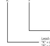
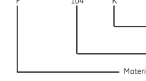
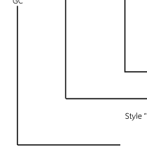
Coding
16 14
K
K
F
104
11
GC GC
GC9
GC6
GC10
GC11
B
G
D
D
0.00808
0.00633
0.00524
0.00443
0.00731
0.00569
0.00468
0.00395
0.00663
0.00512
0.00420
0.00353
0.00602
0.00463
0.00377
0.00316
0.00548
0.00418
0.00339
0.00283
0.00499
0.00379
0.00306
0.00254
0.00456
0.00344
0.00276
0.00229
0.00417
0.00313
0.00250
0.00207
0.00382
0.00285
0.00227
0.00187
0.00351
0.00261
0.00206
0.00169
0.00322
0.00238
0.00187
0.00153
0.00297
0.00218
0.00171
0.00139
0.00274
0.00200
0.00156
0.00127
0.00253
0.00184
0.00143
0.00116
Tolerance Code Letter (See Note 1 and Standard Tolerances)
Zero-power resistance as 25°C (see NOTE 2)
Material System Code Letter (see table on page2)
Lead configuration code letter “K” = adjacent cut leads “P” = opposite cut leads Nominal Diameter in mils: 14= 0.014” nom, 0.016” max; 16 = 0.016” nom, 0.017” max, 11 = 0.011” nom., 0.012” max. Style “GC” denotes GLASS ENCAPSULATED CHIP structure
NOTE 1: Special tolerances are available on request. Consult factory for special resistance tolerances, nonstandard resistances and/or non-standard temperatures.
NOTE 2: The zero-power resistance at 25°C, expressed in ohms, is identified by a three-digit code number. The first two digits represent significant figures, and the last digit specifies the number of zeros to follow. Example: 51 kOhms = “513”. The standard resistance values are from the 24-value series decade as specified in Military Standard MS90178.
1.0 / 1.1 / 1.2 / 1.3 / 1.5 / 1.6 / 1.8 / 2.0 / 2.2 / 2.4 / 2.7 / 3.0 3.3 / 3.6 / 3.9 / 4.3 / 4.7 / 5.1 / 5.6 / 6.2 / 6.8 / 7.5 / 8.2 / 9.1
Amphenol
www.amphenol-sensors.com
© 2014 Amphenol Corporation. All Rights Reserved. Specifications are subject to change without notice.
Advanced Sensors
Other company names and product names used in this document are the registered trademarks or
trademarks of their respective owners.