


 Download PDF
GB320240A JHE
Document overview
- PDF pages: 48
Technical content
Page 1

SPECIFICATIONS FOR
LCD MODULE
Module No. GB320240A
Office Address: Rm. 518,5/F., 101 Shangbu Industrial District,
HuaqiangNorthRoad, Shenzhen, China
TEL : (86)-755-83362489 83617492 FAX: (86)-755-83286396 83365871 E-mail: sales@jhlcd.com jhlcd@21cn.com Website: www.jhlcd.com
- 0 - Issue date: 2006/08/04
Page 2
TABLE OF CONTENTS
LCM NUMBER SYSTEM........................................................................................2
1. GENERAL DESCRIPTION..............................................................................3
2. FEATURES .......................................................................................................3
3. MECHANICAL SPECIFICATION ...............................................................3
4. MECHANICAL DIMENSION .........................................................................4
5. MAXIMUM RATINGS....................................................................................5
6. ELECTRICAL CHARACTERISTICS..........................................................5
7. MODULE FUNCTION DESCRIPTION .......................................................6
8. ELECTRO-OPTICAL CHARACTERISTICS ...........................................37
9. RELIABILITY................................................................................................41
10. PRECAUTIONS FOR USING LCD MODULES .......................................42
11. USING LCD MODULES ...............................................................................44
12. REVISION HISTORY ...................................................................................46
SAMPLE APPROVED REPORT..........................................................................47
- 1 - Issue date: 2006/08/04
Page 3
LCM Number System
GB 320240 A S B D W W D A - V01
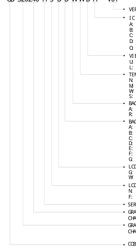
VERSI ON NUMBER: V00~V99 I C TYPE: A: BONDI NG I C, WI TH CONTROLLER B: BONDI NG I C, WI THOUT CONTROLLER C: SMT I C, WI TH CONTROLLER D: SMT I C, WI THOUT CONTROLLER O: OTHER TYPE VI EWI NG DI RECTI ON: U: UPPER( 12: 00) ; D: DOWN( 6: 00) L: LEFT( 9: 00) ; R: RI GHT( 3: 00) ; TEMPERATURE RANGE: N: NORMAL TEMPERATURE RANGE M: MI DDLE TEMPERATURE RANGE W: WI DE TEMPERATURE RANGE S: SUPER WI DE TEMPERATURE RANGE BACKLI GHT COLOR: A: AMBER; B: BLUE; Y: YELLOW- GREEN R: RED; W: WHI TE; O: THER COLOR BACKLI GHT TYPE: A: TRANSFLECTI VE, EL BACKLI GHT B: TRANSMI SSI VE, EL BACKLI GHT C: TRANSFLECTI VE, LED BACKLI GHT D: TRANSMI SSI VE, LED BACKLI GHT E: TRANSFLECTI VE, CCFL BACKLI GHT
F: TRANSMI SSI VE, CCFL BACKLI GHT G: REFLECTI VE, NONE BACKLI GHT LCD COLOR MODE: G: GRAY; Y: YELLOW- GREEN; B: BLUE; W: BLACK- WHI TE; O: OTHER LCD TYPE: N: TN; H: HTN; S: STN F: FSTN; X: OTHER SERI AL NUMBER: A~Z GRAPHI C MODULEs: NUMBER OF COMMONs CHARACTER MODULEs: NUMBER OF LI NE GRAPHI C MODULEs: NUMBER OF SEGMENTs CHARACTER MODULEs: NUMBER OF CHAR. PER LI NE COB & SMT LCM
- 2 - Issue date: 2006/08/04
Page 4
1. GENERAL DESCRIPTION
The GB320240A is a 320 x 240 Dots Graphics LCD module. It has a FSTN panel composed of 320 segments and 240 commons. The LCM can be easily accessed by micro-controller via parallel interface.
2. FEATURES
| Display Mode | Transflective and positive |
| STN(BLUE) module | |
| Display Format | Graphic 320 x 240 dots |
| Input Data | Parallel data input from MPU |
| Multiplexing Ratio | 1/240 Duty |
| Bias | 1/16 Bias |
| Viewing Direction | 6 O’clock |
| Backlight | LED/WHITE |
3. MECHANICAL SPECIFICATION
| Item | Specifications | Unit |
|---|---|---|
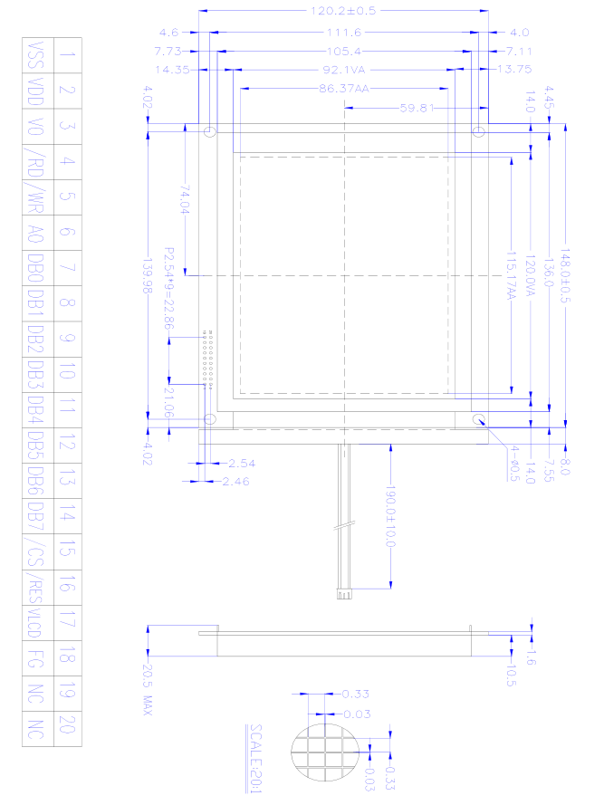
| Dimensional outline | 148.0 x 120.2 x 20.5(max) | mm |
| Resolution | 320segs x 240coms | dots |
| Active area | 115.17(W) x 86.37(H) | mm |
| Dots pitch | 0.36 (W)×0.36(H) | mm |
| Dots size | 0.33(W)×0.33(H) | mm |
- 3 - Issue date: 2006/08/04
Page 5
4. MECHANICAL DIMENSION
- 4 - Issue date: 2006/08/04
Page 6
5. MAXIMUM RATINGS
| Item | Symbol | Min | Max | Unit | Note |
|---|---|---|---|---|---|
| Supply voltage | V - Vss DD | -0.3 | 6.0 | V | |
| V LCD | -0.3 | 30.0 | V | ||
| Input Voltage | V IN | -0.3 | V +0.3 DD | V | |
| Operating temperature | T OPR | -10 | +60 | ℃ | |
| Storage temperature | T STR | -20 | +70 | ℃ | |
| Humidity | --- | --- | 90 | %RH |
6. ELECTRICAL CHARACTERISTICS
| Item | Symbol | Condition | Min. | Typ. | Max. | Unit | |
|---|---|---|---|---|---|---|---|
| Supply Voltage | Logic | V DD | --- | --- | 5.0 | --- | V |
| Input Voltage | H level | V IH | --- | 0.8V DD | --- | V DD | V |
| L level | V IL | V SS | --- | 0.2V DD | |||
| Current Consumption (LCD DRIVER) | I DD | V =5.0V; DD V =24.3V, LCD T =25℃; amb | --- | --- | 50.0 | mA | |
| LCD Driving Voltage | V LCD | Bias=1/16 VLCD=VDD-V0 | --- | 22.4 | --- | V | |
| Current Consumption (With LED BackLight) | I LED | V =5.0V; DD V =4.2V,T =25℃; LED amb | --- | --- | 300 | mA | |
- 5 - Issue date: 2006/08/04
Page 7
7. MODULE FUNCTION DESCRIPTION
7.1. PIN DESCRIPTION
| Pin No. | Symbol | Description |
|---|---|---|
| 1 | VSS | Power supply for Ground(0V) |
| 2 | VDD | Power supply for positive(+5V) |
| 3 | VO | Contrast adjustment voltage |
| 4 | /RD | Read signal |
| 5 | /WR | Write signal |
| 6 | A0 | Data type select |
| 7 | DB0 | 8-bit bi-directional data bus |
| 8 | DB1 | |
| 9 | DB2 | |
| 10 | DB3 | |
| 11 | DB4 | |
| 12 | DB5 | |
| 13 | DB6 | |
| 14 | DB7 | |
| 15 | /CS | Chip signal |
| 16 | /RST | Reset signal |
| 17 | VLCD | Power supply voltage for LCD |
| 18 | FG | For GND |
| 19 | NC | No connection |
| 20 | NC |
- 6 - Issue date: 2006/08/04
Page 8
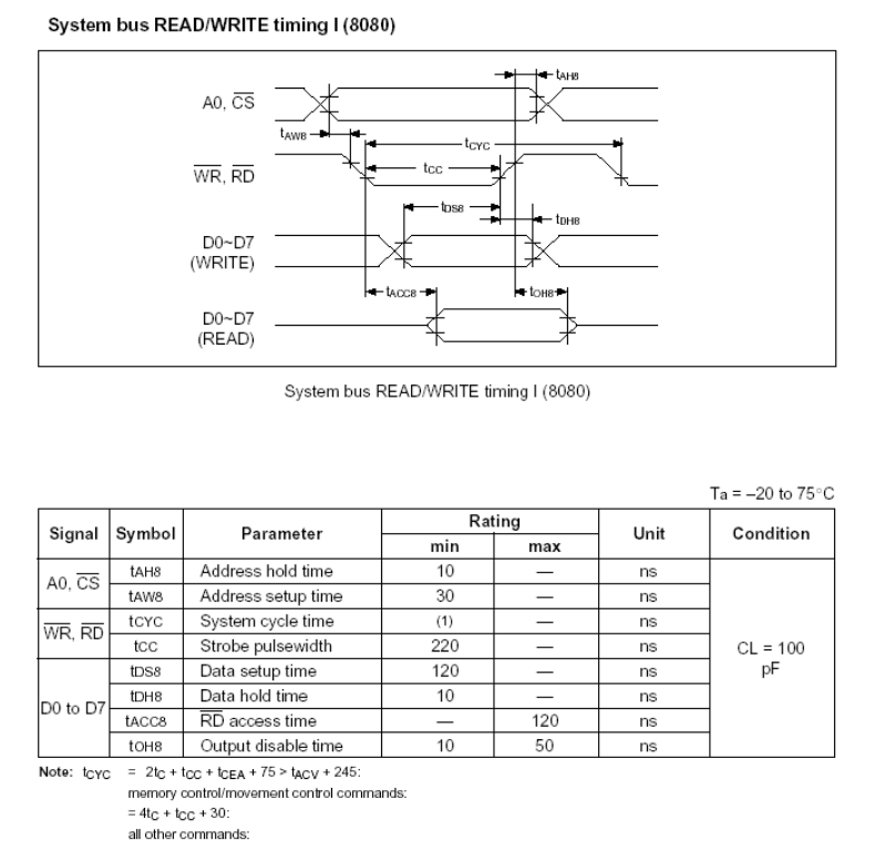
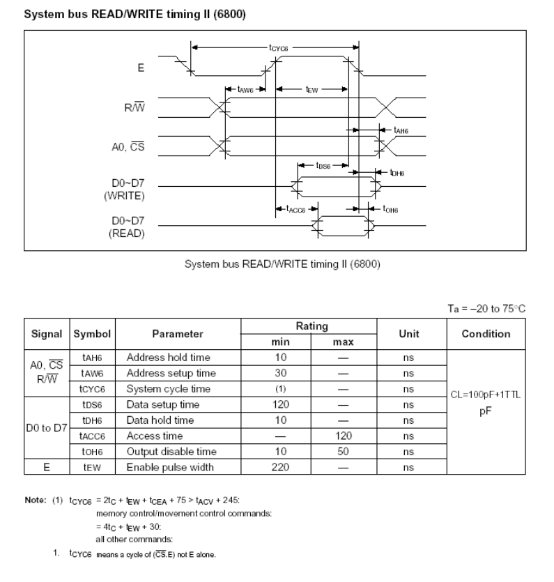
7.2 TIMING CHARACTERISTICS
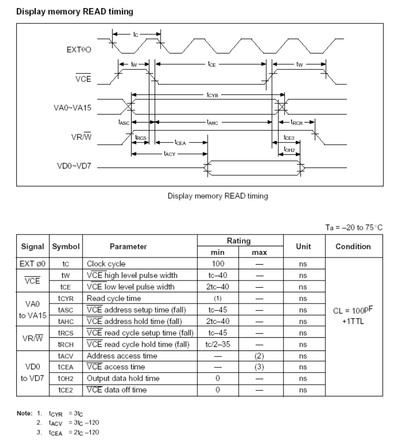
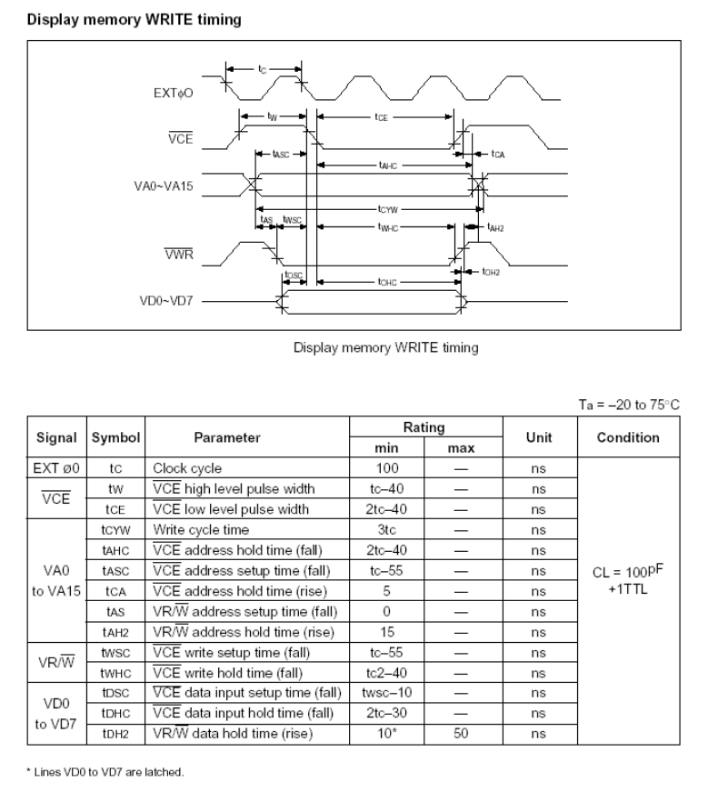
1. SYSTEM BUS READ/WRITE CHARACTERISTIC
- 7 - Issue date: 2006/08/04
Page 9
- 8 - Issue date: 2006/08/04
Page 10
- 9 - Issue date: 2006/08/04
Page 11
- 10 - Issue date: 2006/08/04
Page 12
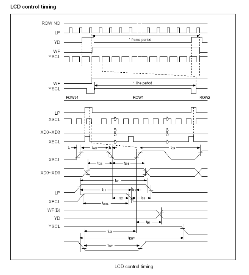
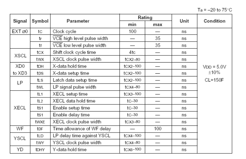
2. DISPLAY CONTROL OUTPUT TIMING
- 11 - Issue date: 2006/08/04
Page 13
- 12 - Issue date: 2006/08/04
Page 14
3. OSCILLATOR TIMING
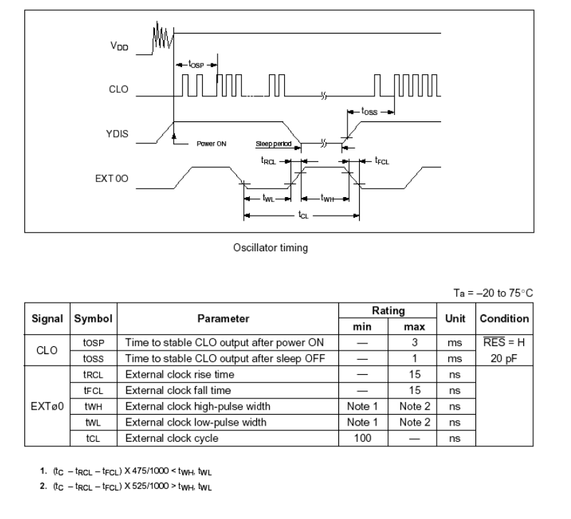
- 13 - Issue date: 2006/08/04
Page 15
4. SLEEP IN COMMAND TIMING
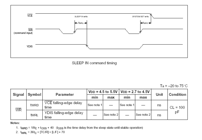
- 14 - Issue date: 2006/08/04
Page 16
5.EXTERNAL OSCILLATOR SIGNAL
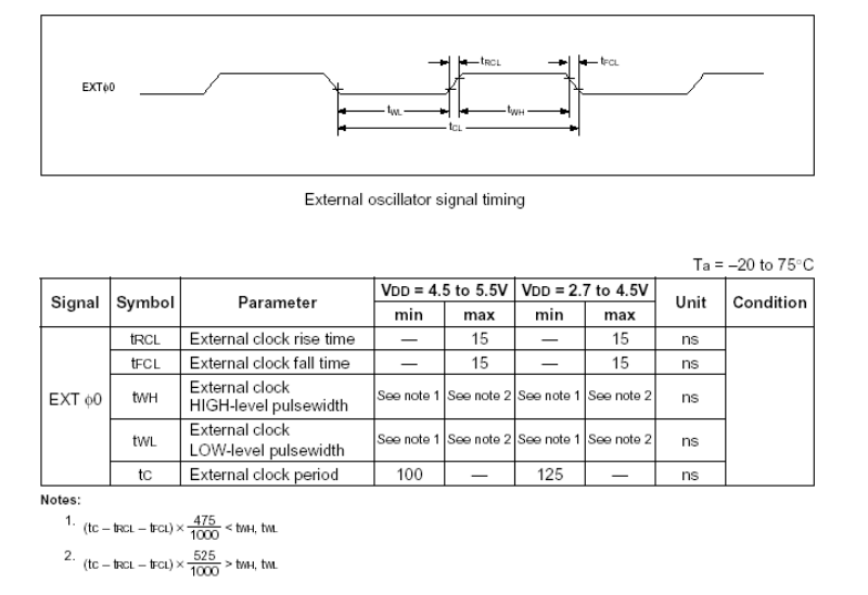
7.3 APPLICATION OF LCM
Circuit Block Diagram
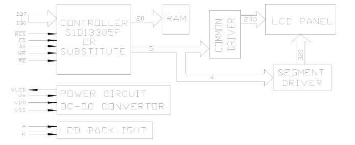
- 15 - Issue date: 2006/08/04
Page 17
7.4 TABLE OF COMMANDS
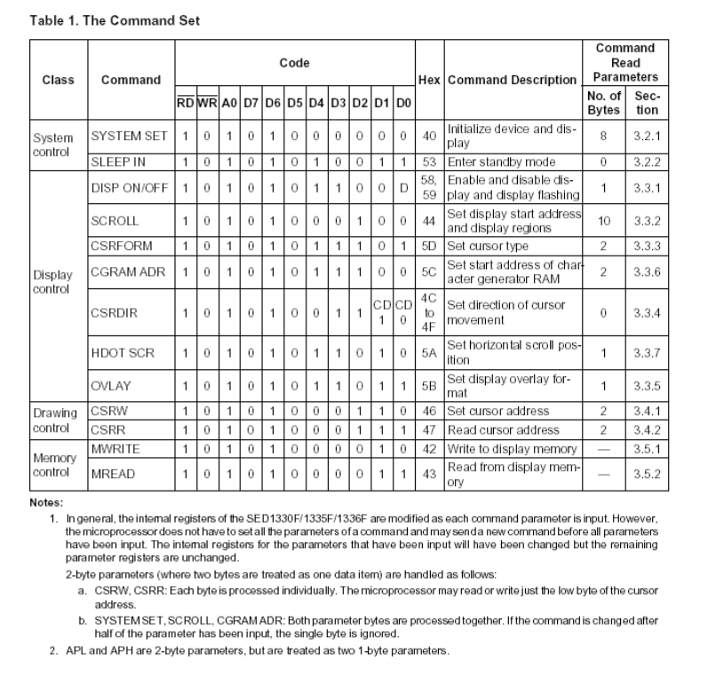
- 16 - Issue date: 2006/08/04
Page 18
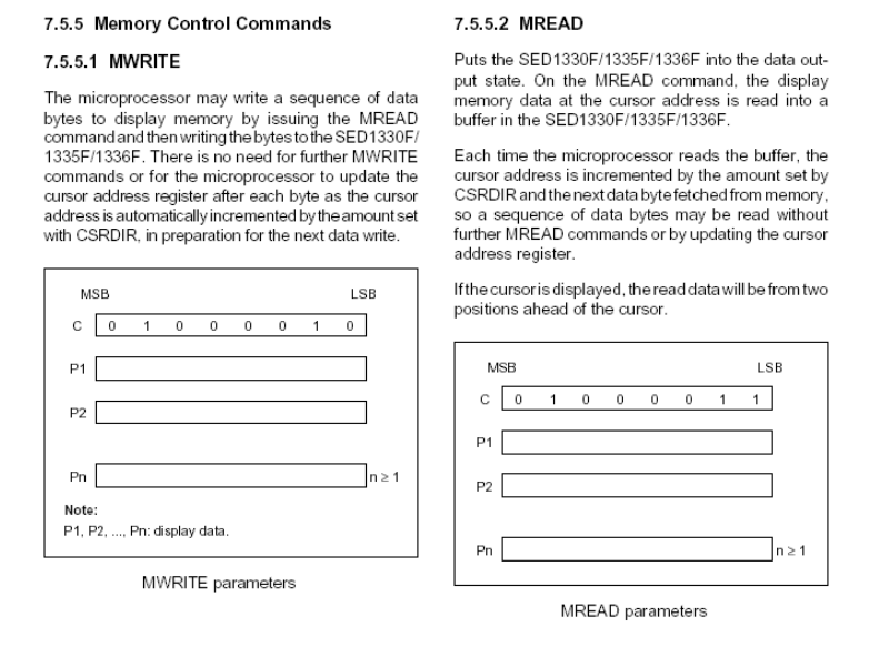
7.5 SYSTEM CONTROL COMMANDS
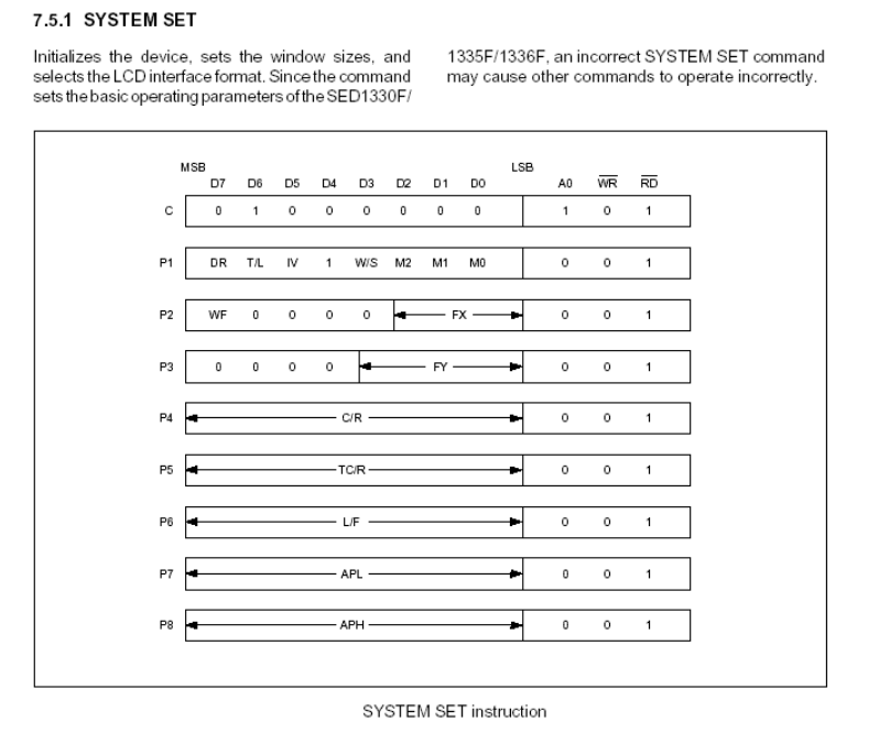
- 17 - Issue date: 2006/08/04
Page 19
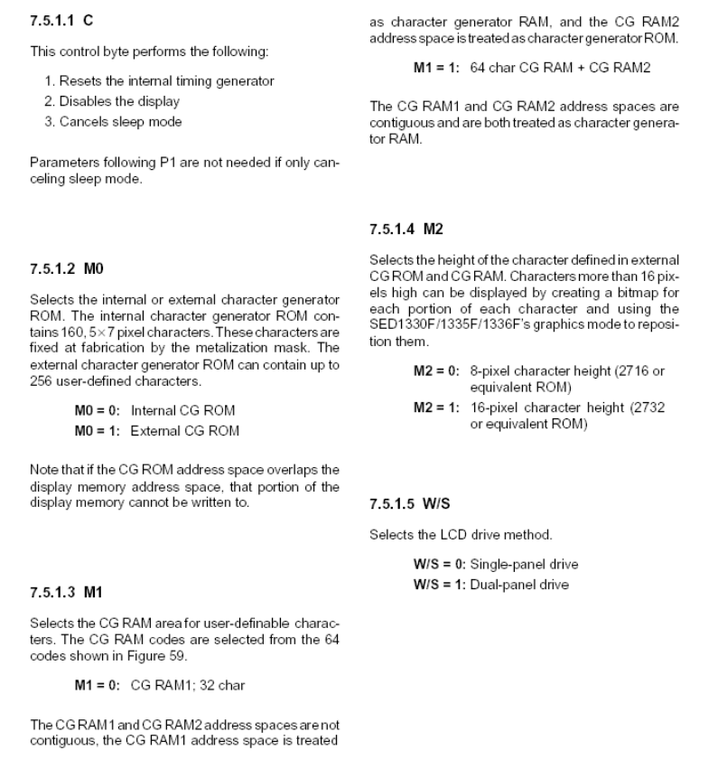
- 18 - Issue date: 2006/08/04
Page 20
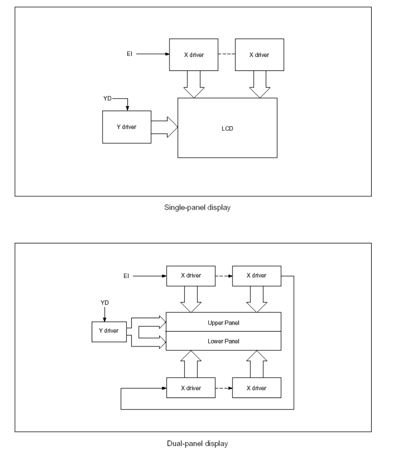
- 19 - Issue date: 2006/08/04
Page 21
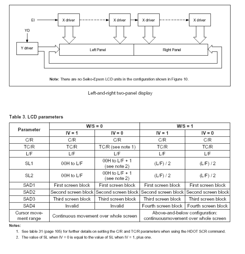
- 20 - Issue date: 2006/08/04
Page 22
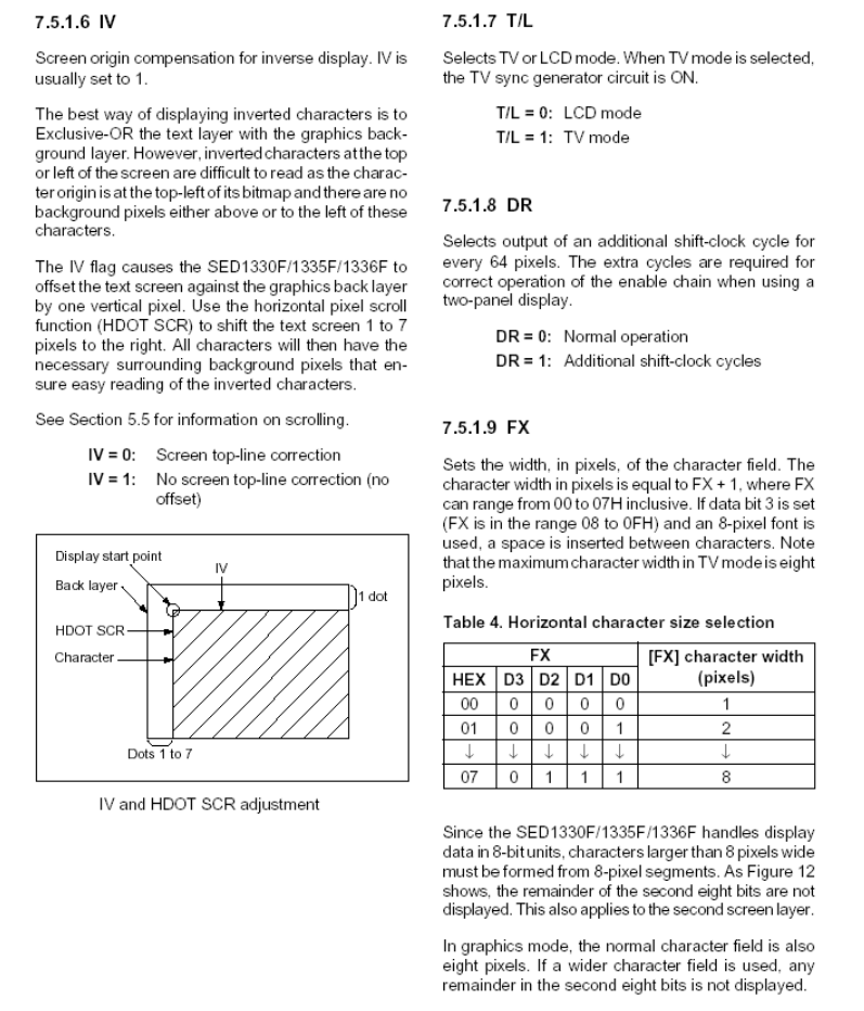
- 21 - Issue date: 2006/08/04
Page 23
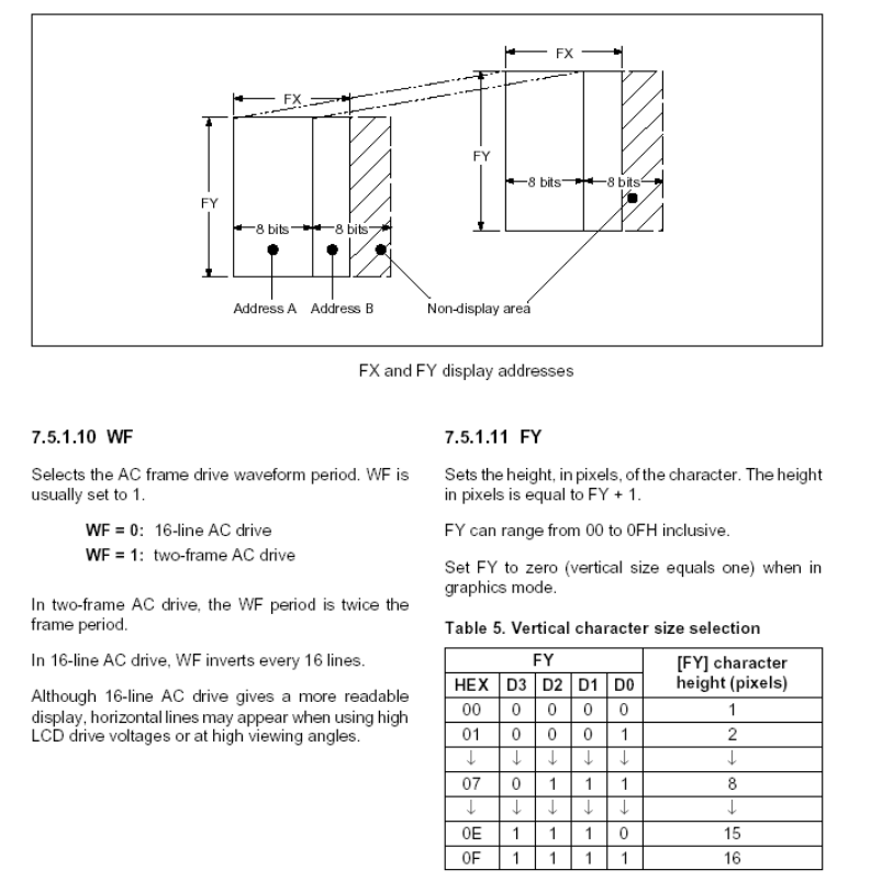
- 22 - Issue date: 2006/08/04
Page 24
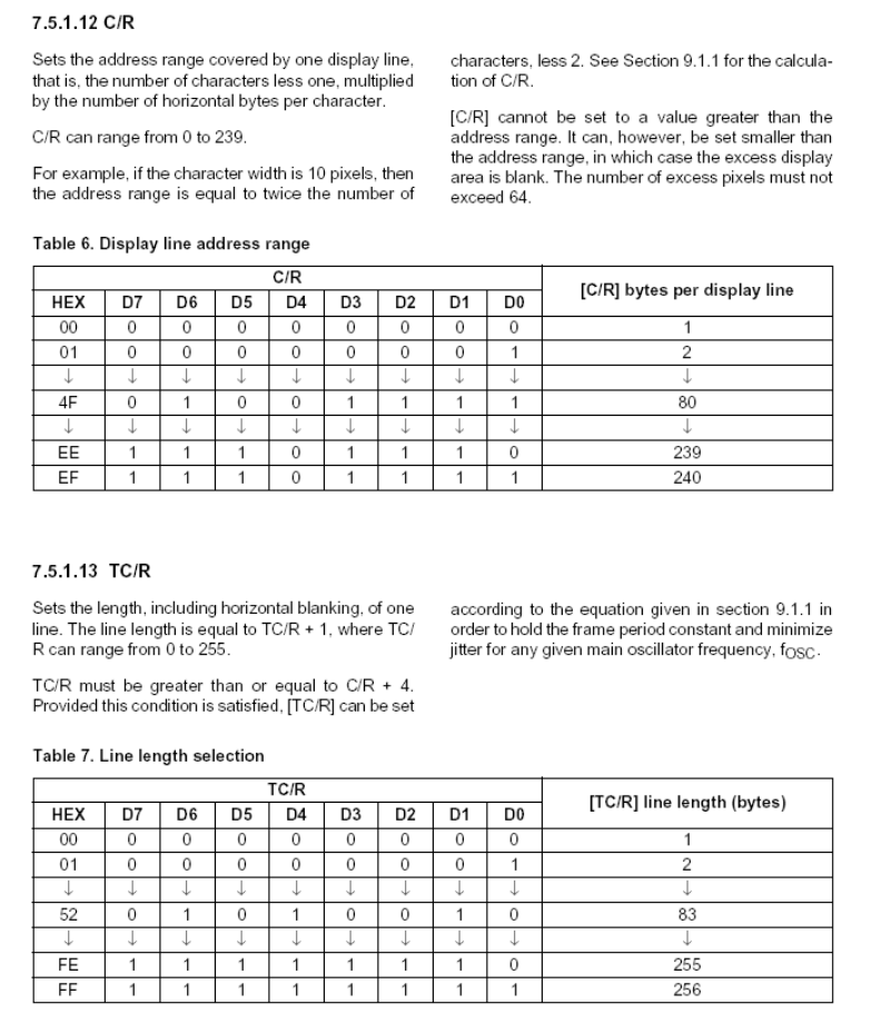
- 23 - Issue date: 2006/08/04
Page 25
- 24 - Issue date: 2006/08/04
Page 26
- 25 - Issue date: 2006/08/04
Page 27
- 26 - Issue date: 2006/08/04
Page 28
- 27 - Issue date: 2006/08/04
Page 29
- 28 - Issue date: 2006/08/04
Page 30
- 29 - Issue date: 2006/08/04
Page 31
- 30 - Issue date: 2006/08/04
Page 32
- 31 - Issue date: 2006/08/04
Page 33
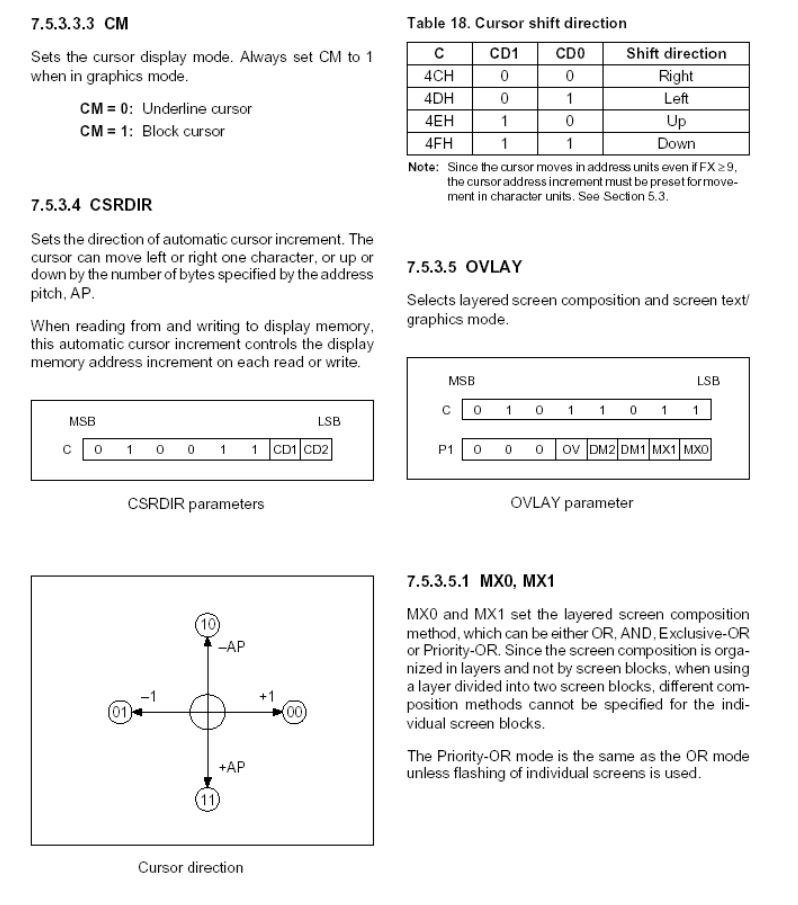
- 32 - Issue date: 2006/08/04
Page 34
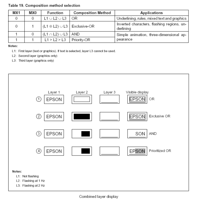
- 33 - Issue date: 2006/08/04
Page 35
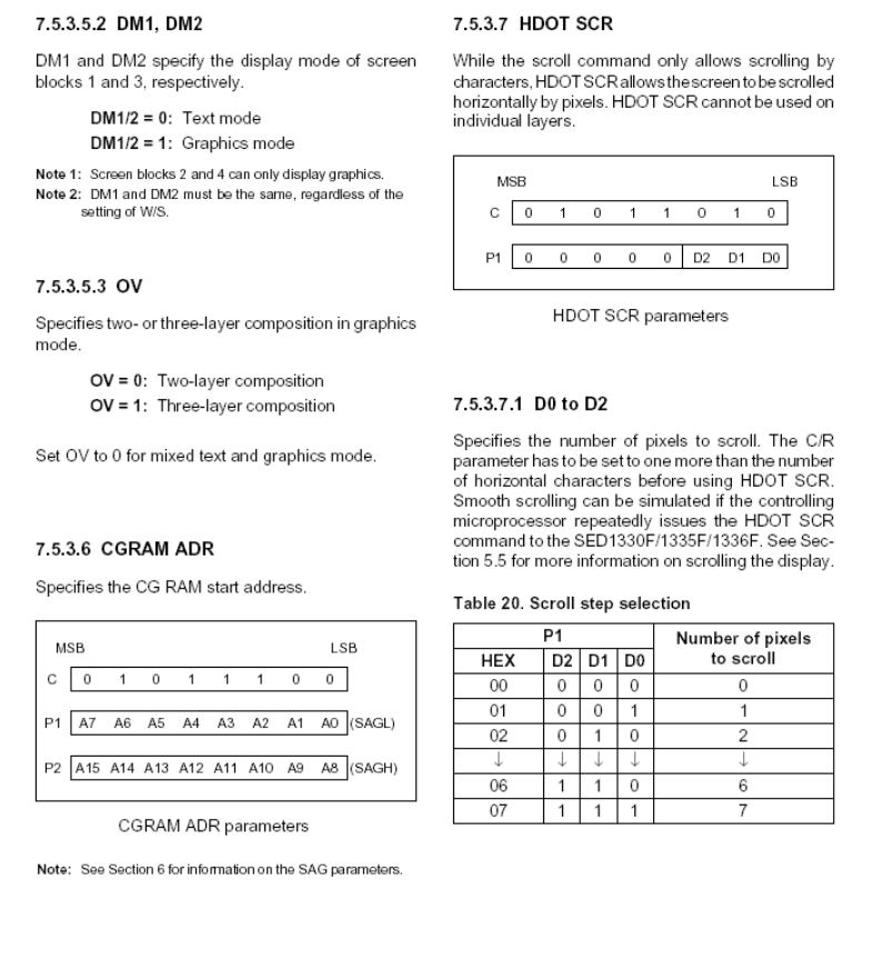
- 34 - Issue date: 2006/08/04
Page 36
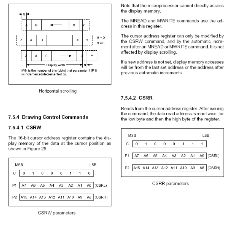
- 35 - Issue date: 2006/08/04
Page 37
- 36 - Issue date: 2006/08/04
Page 38
8. ELECTRO-OPTICAL CHARACTERISTICS
| Item | Symbol | Condition | Temp | Min | Typ. | Max | Units | Note |
|---|---|---|---|---|---|---|---|---|
| LCD driving voltage | VLCD | θ=ψ= 0 | 0℃ | --- | 22.0 | --- | V | NOTE1 |
| 25℃ | 21.8 | 22.4 | 22.9 | |||||
| 50℃ | --- | 22.8 | --- | |||||
| Response Time | Rise Time (Tr) | θ=ψ= 0 | 0℃ | --- | --- | -- | msec | NOTE2 |
| Decay Time (Tf) | --- | ---- | --- | |||||
| Rise Time (Tr) | 25℃ | --- | 225 | 340 | ||||
| Decay Time (Tf) | --- | 240 | 360 | |||||
| Rise Time (Tr) | 50℃ | --- | --- | -- | ||||
| Decay Time (Tf) | --- | --- | -- | |||||
| Contrast Ratio | Cr | θ=ψ= 0 | 25℃ | 5 | 10 | --- | --- | NOTE4 |
| Viewing Angle Range | θ(ψ= 0°) (6”) | ψ= 90° (3”) | ψ=180° (12”) | ψ=270° (9”) | 備註 |
| θ(25℃ ) CR≥2 | 45 | 35 | 25 | 35 | Deg NOTE3 |
z For panel only
- 37 - Issue date: 2006/08/04
Page 39
․Electro-Optical Characteristics Measuring Equipment(DMS501)
Printer
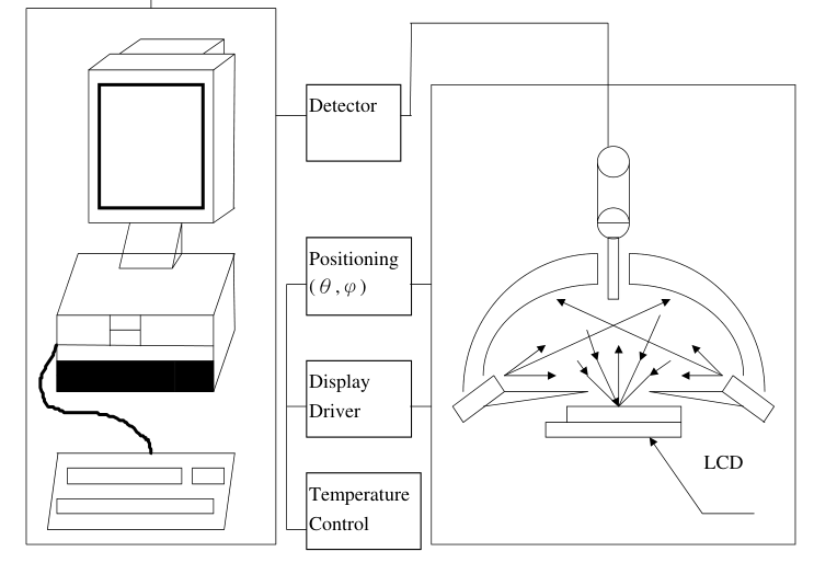
System
Illumination (D65)
- 38 - Issue date: 2006/08/04
Page 40
․Note 1. Definition of Driving Voltage( Vlcd) :
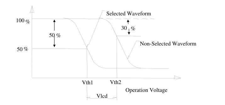
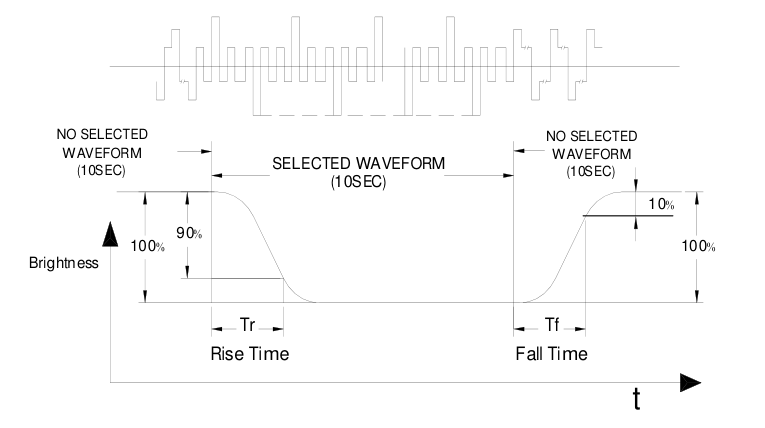
․Note 2. Definition of Optical Response Time :
- 39 - Issue date: 2006/08/04
Page 41
․Note 3. Definition of Viewing Angle θ and ψ :
Normal : θ=0° 12 O’clock Direction
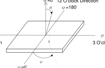
φ=90°
φ=270° 9 O’clock Direction
3 O’clock Direction
Viewing Direction 6 O’clock Direction
․Note 4. Definition of Contrast ratio( CR) :
Brightness of Non-selected Segment (B2)
CR =
Brightness of Selected Segment (B1)
Brightness Curve for Selected Segment
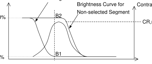
100%
CR,max
0%
Driving Voltage
V,max
- 40 - Issue date: 2006/08/04
Page 42
9. RELIABILITY
9.1. MTBF
The LCD module shall be designed to meet a minimum MTBF value of 50000 hours with normal. (25°C in the room without sunlight)
9.2. TESTS
| NO. | ITEM | CONDITION | CRITERION |
|---|---|---|---|
| 1 | High Temperature Operating | 60℃ 120Hrs | 。No Defect Of Operational Function In Room Temperature Are Allowable. 。IDD of LCM in Pre-and post-test should follow specification |
| 2 | Low Temperature Operating | -10℃ 120Hrs | |
| 3 | High Temperature/ Humidity Non-Operating | 60℃ ,90%RH ,120 Hrs | |
| 4 | High Temperature Non-Operating | 70℃ 120Hrs | |
| 5 | Low Temperature Non-Operating | -20℃ 120Hrs | |
| 6 | Temperature Cycling Non-Operating | -10℃(30Min )↔ 60℃(30Min) 10 CYCLES |
Notes: Judgments should be mode after exposure in room temperature for two hours.
- 41 - Issue date: 2006/08/04
Page 43
10. PRECAUTIONS FOR USING LCD MODULES
10.1. HANDLING PRECAUTIONS
(1) The display panel is made of glass. Do not subject it to a mechanical shock or impact by dropping it. (2) If the display panel is damaged and the liquid crystal substance leaks out, be sure not to get any in your mouth. If the substance contacts your skin or clothes, wash it off using soap and water. (3) Do not apply excessive force to the display surface or the adjoining areas since this may cause the color tone to vary. (4) The polarizer covering the display surface of the LCD module is soft and easily scratched. Handle this polarizer carefully. (5) If the display surface becomes contaminated, breathe on the surface and gently wipe it with a soft
dry cloth. If it is heavily contaminated, moisten a cloth with one of the following solvents: - Isopropyl alcohol - Ethyl alcohol (6) Solvents other than those above mentioned may damage the polarizer. Especially, do not use the following: - Water - Ketone - Aromatic solvents (7) Extra care to minimize corrosion of the electrode. Water droplets, moisture condensation or a current flow in a high-humidity environment accelerates corrosion of the electrode. (8) Install the LCD Module by using the mounting holes. When mounting the LCD Module, make sure it is free of twisting, warping and distortion. In particular, do not forcibly pull or bend the I/O cable or the backlight cable.
(9) Do not attempt to disassemble or process the LCD Module. (10) NC terminal should be open. Do not connect anything. (11) If the logic circuit power is off, do not apply the input signals. (12) To prevent destruction of the elements by static electricity, be careful to maintain an optimum work environment.
- Be sure to ground the body when handling he LCD Module. - Tools required for assembling, such as soldering irons, must be properly grounded. -To reduce the amount of static electricity generated, do not conduct assembling and other work under dry conditions.
- 42 - Issue date: 2006/08/04
Page 44
-The LCD Module is coated with a film to protect the display surface. Exercise care when peeling off this protective film since static electricity may be generated.
10.2. STORAGE CONDITIONS
When storing, avoid the LCD module to be exposed to direct sunlight of fluorescent lamps. For stability, to keep it away form high temperature and high humidity environment (The best condition is : 23±5°C, 45±20%RH). ESD protection is necessary for long-term storage also.
10.3. OTHERS
Liquid crystals solidify under low temperature (below the storage temperature range) leading to defective orientation or the generation of air bubbles (black or white). Air bubbles may also be generated if the module is subject to a low temperature. If the LCD Module have been operating for a long time showing the same display patterns the display patterns may remain on the screen as ghost images and a slight contrast irregularity may also appear. A normal operating status can be recovered by suspending use for some time. It should be noted that this phenomenon does not adversely affect performance reliability. To minimize the performance degradation of the LCD Module resulting from destruction caused by
static electricity etc. exercise care to avoid holding the following sections when handling the modules. - Exposed area of the printed circuit board. - Terminal electrode sections.
- 43 - Issue date: 2006/08/04
Page 45
11. Using LCD modules
11.1 LIQUID CRYSTAL DISPLAY MODULES
LCD is composed of glass and polarizer. Pay attention to the following items when handling. (1) Please keep the temperature within specified range for use and storage. Polarization degradation, bubble generation or polarizer peel-off may occur with high temperature and high humidity. (2) Do not touch, push or rub the exposed polarizers with anything harder than a HB pencil lead (glass, tweezers, etc). (3) N-hexane is recommended for cleaning the adhesives used to attach front/rear polarizers and reflectors made of organic substances, which will be damaged by chemicals such as acetone, toluene, toluene, ethanol and isopropyl alcohol. (4) When the display surface becomes dusty, wipe gently with absorbent cotton or other soft material
like chamois soaked in petroleum ether. Do not scrub hard to avoid damaging the display surface. (5) Wipe off saliva or water drops immediately, contact with water over a long period of time may cause deformation or color fading. (6) Avoid contacting oil and fats. (7) Condensation on the surface and contact with terminals due to cold will damage, stain or polarizers. After products are tested at low temperature they must be warmed up in a container before coming is contacting with room temperature air. (8) Do not put or attach anything on the display area to avoid leaving marks on. (9) Do not touch the display with bare hands. This will stain the display area and degrade insulation
between terminals (some cosmetics are determinate to the polarizers). (10)As glass is fragile, it tends to become or chipped during handling especially on the edges. Please avoid dropping or jarring.
11.2 INSTALLING LCD MODULE
Attend to the following items when installing the LCM. (1) Cover the surface with a transparent protective plate to protect the polarizer and LC cell. (2) When assembling the LCM into other equipment, the spacer to the bit between the LCM and the fitting plate should have enough height to avoid causing stress to the module surface, refer to the individual specifications for measurements. The measurement tolerance should be ±0.1mm.
11.3 ELECTRO-STATIC DISCHARGE CONTROL
Since this module uses a CMOS LSI, the same careful attention should be paid for electrostatic discharge as for an ordinary CMOS IC.
- 44 - Issue date: 2006/08/04
Page 46
(1) Make certain that you are grounded when handing LCM. (2) Before removing LCM from its packing case or incorporating it into a set, be sure the module and your body have the same electric potential. (3) When soldering the terminal of LCM, make certain the AC power source for the soldering iron does not leak. (4) When using an electric screwdriver to attach LCM, the screwdriver should be of ground potentiality to minimize as much as possible any transmission of electromagnetic waves produced sparks coming from the commutator of the motor. (5) As far as possible, make the electric potential of your work clothes and that of the workbenches to the ground potential.
(6) To reduce the generation of electro-static discharge, be careful that the air in the work is not too dried. A relative humidity of 50%-60% is recommended.
11.4 PRECAUTIONS FOR OPERATION
(1) Viewing angle varies with the change of liquid crystal driving voltage (Vo). Adjust Vo to show the best contrast. (2) Driving the LCD in the voltage above the limit will shorten its lifetime. (3) Response time is greatly delayed at temperature below the operating temperature range. However, this does not mean the LCD will be out of the order. It will recover when it returns to the specified temperature range. (4) If the display area is pushed hard during operation, the display will become abnormal. However, it will return to normal if it is turned off and then on. (5) Condensation on terminals can cause an electrochemical reaction disrupting the terminal circuit.
Therefore, this product must be used and stored within the specified condition of 23±5°C, 45±20%RH. (6) When turning the power on, input each signal after the positive/negative voltage becomes stable.
11.5 SAFETY
(1) It is recommended to crush damaged or unnecessary LCDs into pieces and wash them off with solvents such as acetone and ethanol, which should later be burned. (2) If any liquid leaks out of a damaged glass cell and comes in contact with the hands, wash off thoroughly with soap and water.
- 45 - Issue date: 2006/08/04
Page 47
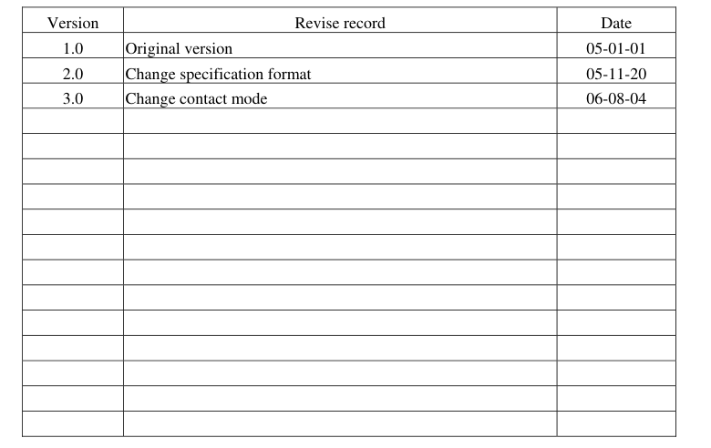
12.REVISION HISTORY
- 46 - Issue date: 2006/08/04
Page 48
SAMPLE APPROVED REPORT
(样品确认单)
| SAMPLE MODEL NO. (样品型号) | GB320240A |
| SAMPLE SERIES NUMBER NO. (样品序号) | |
| SAMPLE QUANTITY (样品数量) | |
| COLOR/TYPE (底色/类型) | |
| VIEWING DIRECTION (视角) | |
| DRIVING METHOD (驱动参数) | 1/240Duty, 1/16Bias |
| LOGIC VOLTAGE (工作电压) | 5.0V |
| LCD VOP (LCD 驱动电压) | 22.4V |
| OPERATING TEMP. (操作温度) ℃ | |
| STORAGE TEMP. (储存温度) ℃ | |
| POLARIZER----FRONT (首偏光片) | |
| POLARIZER----BACK (后偏光片) | |
| CONTROLLER/DRIVER IC(控制/驱动IC) | SED1335F0A/S6B0086 |
| BACKLIGHT COLOR/TYPE (背光源类型/颜色) | |
| DRAWING REV/NO./QUANTITY (图纸版本/数量) | |
| SPECIFICATION (规格书 份数) | |
| REMARKS: (备注) WRIT BY:_________ DATE:_________ APROV BY:_________ DATE:________ | |
| CUSTOMER’S APPROVAL (客户确认): 1) FUNCTION (功能): OK N.G. 2) DRIVER CONDITION (驱动条件): OK N.G. 3) DISPLAY MODE (显示模式): OK N.G. 4) VIEWING ANGLE (视角): OK N.G. 5) BACKLIGHT (背光源): OK N.G. 6) DISPLAYING PATTERN (显示效果): OK N.G. CUSTOMER’S CONCLUSIONS (客户意见):______________________________________ _______________________________________________________________________________ ________________________________________ CUSTOMER’S SIGNATURE(客户签名):_____________ DATE (日期):___________ | |
- 47 - Issue date: 2006/08/04