
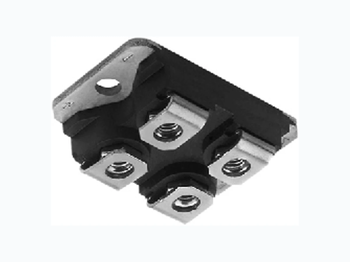
GA200SA60SP VISHAY
Document overview
- Manufacturer or author: Provided By www.digicamel.com(free datasheet download site)
- PDF pages: 9
Technical content
Insulated Gate Bipolar Transistor Ultralow VCE(on), 342 A GA200SA60SP Vishay Semiconductors Document Number: 94363 For technical ques tions within your region, please contact one of the following: www.vishay.com Revision: 22-Jul-10 DiodesAmericas@vishay.com, DiodesAsia@vishay.com, DiodesEurope@vishay.com 1 Note (1) Maximum I RMS current admitted 100 A to do not exceed the maximum temperature of terminals
FEATURES
- Standard: Optimized for minimum saturation voltage and low speed up to 5 kHz
- Lowest conduction losses available
- Fully isolated package (2500 V AC)
- Very low internal inductance (5 nH typical)
- Industry standard outline
- UL approved file E78996
- Compliant to RoHS directive 2002/95/EC
- Designed and qualified for industrial level BENEFITS
- Designed for increased operating efficiency in power conversion: UPS, SMPS, TIG welding, induction heating
- Easy to assemble and parallel
- Direct mounting to heatsink
- Plug-in compatible with other SOT-227 packages Note (1) Maximum IRMS current admitted 100 A to do not exceed the maximum temperature of terminals PRODUCT SUMMARY VCES 600 V VCE(on) (typical) at 200 A, 25 °C 1.33 V IC at TC = 97 °C (1) 200 A SOT-227 ABSOLUTE MAXIMUM RATINGS PARAMETER SYMBOL TEST CONDITIONS MAX. UNITS Collector to emitter breakdown voltage V CES 600 V Continuous collector current I C (1) TC = 25 °C 342 A TC = 97 °C 200 Pulsed collector current I CM Repetitive rating; VGE = 20 V, pulse width limited by maximum junction temperature See fig. 15 400 Clamped Inductive load current I LM VCC = 80 % (VCES), VGE = 20 V, See fig. 14 400 Gate to emitter voltage V GE ± 20 V Reverse voltage avalanche energy E ARV Repetitive rating; pulse width limited by maximum junction temperature 155 mJ RMS isolation voltage V ISOL Any terminal to case, t = 1 minute 2500 V Maximum power dissipation P D TC = 25 °C 781 W TC = 100 °C 312 Operating junction and storage temperature range T J, TStg - 55 to + 150 °C Mounting torque 6-32 or M3 screw 12 (1.3) lbf in (N m) THERMAL AND MECHANICAL SPECIFICATIONS PARAMETER SYMBOL TYP. MAX. UNITS Junction to case R thJC -0 . 1 6 °C/W Case to sink, flat, greased surface R thCS 0.05 - Weight of module 30 - g
Vishay Semiconductors Insulated Gate Bipolar Transistor Ultralow VCE(on), 342 A www.vishay.com For technical qu estions within your region, please contact one of the following: Document Number: 94363 2 DiodesAmericas@vishay.com, DiodesAsia@vishay.com, DiodesEurope@vishay.com Revision: 22-Jul-10 Notes (1) Pulse width 80 μs; duty factor 0.1 % (2) Pulse width 5.0 μs, single shot ELECTRICAL SPECIFICATIONS (TJ = 25 °C unless otherwise noted) PARAMETER SYMBOL TEST CONDITI ONS MIN. TYP. MAX. UNITS Collector to emitter breakdown voltage V (BR)CES VGE = 0 V, IC = 250 μA 600 - - V Emitter to collector breakdown voltage V(BR)ECS (1) VGE = 0 V, IC = 1.0 A 18 - - Temperature coeff. of breakdown voltage V(BR)CES/TJ VGE = 0 V, IC = 1.0 mA - 0.62 - V/°C Collector to emitter saturation voltage V CE(on) IC = 100 A VGE = 15 V See fig. 2, 5 - 1.10 1.3 V IC = 200 A - 1.33 - IC = 100 A, TJ = 150 °C - 1.02 - Gate threshold voltage V GE(th) VCE = VGE, IC = 250 μA 3.0 - 6.0 Temperature coeff. of threshold voltage VGE(th)/TJ VCE = VGE, IC = 2 mA - - 10 - mV/°C Forward transconductance g fe (2) VCE = 100 V, IC = 100 A 90 150 - S Zero gate voltage collector current I CES VGE = 0 V, VCE = 600 V - - 1.0 mA VGE = 0 V, VCE = 10 V, TJ = 150 °C - - 10 Gate to emitter leakage current I GES VGE = ± 20 V - - ± 250 nA SWITCHING CHARACTERISTICS (TJ = 25 °C unless otherwise specified) PARAMETER SYMBOL TEST CONDITI ONS MIN. TYP. MAX. UNITS Total gate charge (turn-on) Q g IC = 100 A VCC = 400 V VGE = 15 V; See fig. 8 - 770 1200 nCGate emitter charge (turn-on) Q ge - 100 150 Gate collector charge (turn-on) Q gc - 260 380 Turn-on delay time t d(on) TJ = 25 °C IC = 100 A VCC = 480 V VGE = 15 V Rg = 2.0 Energy losses include “tail” See fig. 9, 10, 13 -7 8- ns Rise time t r -5 6- Turn-off delay time t d(off) - 890 1300 Fall time t f - 390 580 Turn-on switching loss E on -0 . 9 8- mJTurn-off switching loss E off - 17.4 - Total switching loss E ts - 18.4 25.5 Turn-on delay time t d(on) TJ = 150 °C IC = 100 A, VCC = 480 V VGE = 15 V, Rg = 2.0 Energy losses include “tail” See fig. 10, 11, 13 -7 2- ns Rise time t r -6 0- Turn-off delay time t d(off) -1 5 0 0- Fall time t f -6 6 0- Total switching loss E ts - 35.7 - mJ Internal emitter inductance L E Between lead, and center of the die contact -5 . 0- n H Input capacitance C ies VGE = 0 V VCC = 30 V f = 1.0 MHz; See fig. 7 - 16 250 - pFOutput capacitance C oes -1 0 4 0- Reverse transfer capacitance C res -1 9 0-
Insulated Gate Bipolar Transistor Ultralow VCE(on), 342 A Vishay Semiconductors Document Number: 94363 For technical ques tions within your region, please contact one of the following: www.vishay.com Revision: 22-Jul-10 DiodesAmericas@vishay.com, DiodesAsia@vishay.com, DiodesEurope@vishay.com 3 Fig. 1 - Typical Load Current vs. Frequency (Load Current = IRMS of Fundamental) Fig. 2 - Typical Output Characteristics Fig. 3 - Typical Transfer Characteristics Fig. 4 - Maximum Collector Current vs. Case Temperature Fig. 5 - Typical Collector to Emitter Voltage vs. Junction Temperature For both: Duty cycle: 50 % TJ = 125 °C Tsink = 90 °C Gate drive as specified Power dissipation = 140 W 250 0.1 f - Frequency (kHz) Load Current (A) 1 10 100 200 150 100 Clamp voltage: 80 % of rated Triangular wave: I 60 % of rated voltage Ideal diodes Square wave: I 100 1000 VCE - Collector to Emitter Voltage (V) IC - Collector to Emitter Current (A) VGE = 15 V 20 µs pulse width TJ = 150 °C TJ = 25 °C 100 1000 567 VGE - Gate to Emitter Voltage (V) IC - Collector to Emitter Current (A) TJ = 150 °C TJ = 25 °C VCC = 50 V 5 µs pulse width 120 160 100 140 0 50 100 150 250 200 300 350 TC - Case Temperature (°C) Maximum DC Collector Current (A) DC - 60 - 40 - 20 0 20 40 60 80 100 120 140 160 TJ - Junction Temperature (°C) VCE - Collector to Emitter Voltage (V) VGE = 15 V 80 µs pulse width IC = 400 A IC = 200 A IC = 100 A
Vishay Semiconductors Insulated Gate Bipolar Transistor Ultralow VCE(on), 342 A www.vishay.com For technical qu estions within your region, please contact one of the following: Document Number: 94363 4 DiodesAmericas@vishay.com, DiodesAsia@vishay.com, DiodesEurope@vishay.com Revision: 22-Jul-10 Fig. 6 - Maximum Effective Transient Thermal Impedance, Junction to Case Fig. 7 - Typical Capacitance vs. Collector to Emitter Voltage Fig. 8 - Typical Gate Charge vs. Gate to Emitter Voltage Fig. 9 - Typical Switching Losses vs. Gate Resistance Fig. 10 - Typical Switching Losses vs. Junction Temperature 0.001 0.01 0.1 0.0001 0.001 0.01 0.1 1 100 10 t1 - Rectangular Pulse Duration (s) ZthJC - Thermal Response D = 0.75 D = 0.50 D = 0.25 D = 0.10 D = 0.05 D = 0.02 D = 0.01 Single pulse (thermal resistance) 1 10 100 6000 12 000 18 000 24 000 30 000 VCE - Collector to Emitter Voltage (V) C - Capacitance (pF) VGE = 0 V, f = 1 MHz Cies = Cge + Cgc, Cce shorted Cres = Cgc Coes = Cce + Cgc Cies Coes Cres 0 200 400 600 800 QG - Total Gate Charge (nC) VGE - Gate to Emitter Voltage (V) VCC = 400 V IC = 100 A 0 1 02 03 04 05 0 Rg - Gate Resistance (Ω) Total Switching Losses (mJ) VCC = 480 V VGE = 15 V TJ = 25 °C IC = 200 A Total Switching Losses (mJ) - 60 - 40 - 20 0 20 40 60 80 100 120 140 160 100 1000 TJ - Junction Temperature (°C) IC = 200 A IC = 100 A IC = 350 A RG = 2.0 Ω VGE = 15 V VCC = 480 V
Insulated Gate Bipolar Transistor Ultralow VCE(on), 342 A Vishay Semiconductors Document Number: 94363 For technical ques tions within your region, please contact one of the following: www.vishay.com Revision: 22-Jul-10 DiodesAmericas@vishay.com, DiodesAsia@vishay.com, DiodesEurope@vishay.com 5 Fig. 11 - Typical Switching Losses vs. Collector Current Fig. 12 - Turn-Off SOA Fig. 13a - Clamped Inductive Load Test Circuit Fig. 13b - Pulsed Collector Current Test Circuit Fig. 14a - Switching Lost Test Circuit Total Switching Losses (mJ) 100 150 200 250 300 350 120 160 IC - Collector Current (A) RG = 2.0 Ω TJ = 150 °C VCC = 480 V VGE = 15 V IC - Collector Current (A) 100 1000 1 10 100 1000 Safe operating area VCE - Collector to Emitter Voltage (V) VGE = 20 V TJ = 125 °C D.U.T. 50 V L VC* * Driver same type as D.U.T.; VC = 80 % of VCE (max) Note: Due to the 50 V power supply, pulse width and inductor will increase to obtain rated Id 1000 V 480 V 4 x IC at 25 °C 480 µF 960 V
0 V to 480 V
RL == 50 V Driver* 1000 V D.U.T. IC VC L * Driver same type as D.U.T., VC = 480 V
Vishay Semiconductors Insulated Gate Bipolar Transistor Ultralow VCE(on), 342 A www.vishay.com For technical qu estions within your region, please contact one of the following: Document Number: 94363 6 DiodesAmericas@vishay.com, DiodesAsia@vishay.com, DiodesEurope@vishay.com Revision: 22-Jul-10 Fig. 14b - Switching Loss Waveforms ORDERING INFORMATION TABLE t = 5 µstd (on) tftr 90 % td (off) 10 % 90 % 10 % 5 % VC IC Eon Eoff Ets = (Eon + Eoff) 1 - Insulated Gate Bipolar Transistor (IGBT) 2 - Generation 4, IGBT silicon, DBC construction 3 - Current rating (200 = 200 A) 4 - Single switch, no diode 5 - SOT-227 6 - Voltage rating (60 = 600 V) 8 - None = Standard production P = Lead (Pb)-free 7 - Speed/type (S = Standard speed) Device code 513 24 678 G A 200 S A 60 S P
Insulated Gate Bipolar Transistor Ultralow VCE(on), 342 A Vishay Semiconductors Document Number: 94363 For technical ques tions within your region, please contact one of the following: www.vishay.com Revision: 22-Jul-10 DiodesAmericas@vishay.com, DiodesAsia@vishay.com, DiodesEurope@vishay.com 7 CIRCUIT CONFIGURATION LINKS TO RELATED DOCUMENTS Dimensions www.vishay.com/doc?95036 Packaging information www.vishay.com/doc?95037 3 (C) 2 (G) 1, 4 (E) Lead assignment E C GE N-channel
Document Number: 95036 For tec hnical questions, contact: indmodules@vishay.com www.vishay.com Revision: 28-Aug-07 1 SOT-227 Outline Dimensions Vishay Semiconductors DIMENSIONS in millimeters (inches) Notes
- Dimensioning and toleranc ing per ANSI Y14.5M-1982
- Controlling dime nsion: millimeter 38.30 (1.508) 37.80 (1.488) -A- 12.50 (0.492) 7.50 (0.295) Ø 4.40 (0.173) Ø 4.20 (0.165) 30.20 (1.189) 29.80 (1.173) 15.00 (0.590) 25.20 (0.992) -B- R full Chamfer 2.00 (0.079) x 45° 2.10 (0.082) 1.90 (0.075) 8.10 (0.319) 7.70 (0.303)4 x 2.10 (0.082) 1.90 (0.075) -C- 0.12 (0.005) 12.30 (0.484) 11.80 (0.464) MM M0.25 (0.010) CA B 4 x M4 nuts
Document Number: 91000 www.vishay.com Revision: 11-Mar-11 1 Disclaimer Legal Disclaimer Notice Vishay ALL PRODUCT, PRODUCT SPECIFICATIONS AND DATA AR E SUBJECT TO CHANGE WITHOUT NOTICE TO IMPROVE RELIABILITY, FUNCTION OR DESIGN OR OTHERWISE. Vishay Intertechnology, Inc., its affiliates, agents, and employees, and all persons acting on its or their behalf (collectivel y, “Vishay”), disclaim any and all liability for any errors, inaccuracies or incompleteness contained in any datasheet or in any other disclosure relating to any product. Vishay makes no warranty, representation or guarantee regarding the suitability of the products for any particular purpose or the continuing production of any product. To the maximum extent permitted by applicable law, Vishay disclaims (i) any and all liability arising out of the application or use of any product, (ii) any and all liability, incl uding without limitation specia l, consequential or incidental dama ges, and (iii) any and all impl ied warranties, including warran ties of fitness for particular purpose, non-infringement and merchantability. Statements regarding the suitability of pro ducts for certain types of applications are based on Vishay’s knowledge of typical requirements that are often placed on Vishay products in gene ric applications. Such statements are not binding statements about the suitability of products for a partic ular application. It is the customer’s responsibility to validate that a particu lar product with the properties described in th e product specification is su itable for use in a particul ar application. Parameters provided in datasheets an d/or specifications may vary in different applications and perfo rmance may vary over time. All operating parameters, including typical pa rameters, must be validated for each customer application by the customer’s technical experts. Product specifications do not expand or otherwise modify Vishay’s term s and conditions of purchase, including but not limited to the warranty expressed therein. Except as expressly indicated in writing, Vishay products are not designed for use in medical, life-saving, or life-sustaining applications or for any other application in which the failure of the Vishay product co uld result in person al injury or death. Customers using or selling Vishay products not expressly indicated for use in such applications do so at their own risk and agree to fully indemnify and hold Vishay and it s distributors harmless from and against an y and all claims, liabilities, expenses and damages arising or resulting in connection with such use or sale, including attorneys fees, even if such claim alleges that Vishay or its distributor was negligent regarding the design or manufacture of the part. Please contact authorized Vishay personnel to obtain written terms and conditions regarding products designed for such applications. No license, express or implied, by estoppel or otherwise, to any intellectual property rights is granted by this document or by any conduct of Vishay. Product names and markings noted herein may be trademarks of their respective owners.