
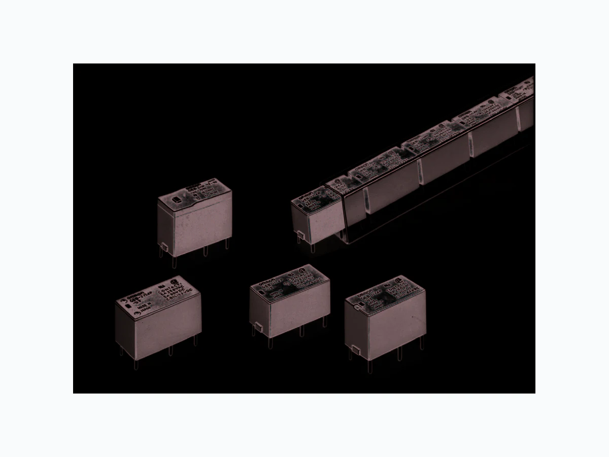
G6B ETC1
Document overview
- Manufacturer or author: Provided By www.digicamel.com(FREE DATASHEET DOWNLOAD SITE)
- PDF pages: 7
Technical content
PCB Power Relay – G6B Model Number Legend
Ordering Information
Sub-miniature Relay that Switches up to 5 A ■ Sub-miniature: 20 x 10 x 10 mm (L x W x H). ■ Low power consumption: 200 mW. ■ Unique moving loop armature reduces relay size, magnetic interference, and contact bounce time. ■ Single- and double-winding latching types also available. Rated coil voltage Note: When ordering, add the rated coil voltage to the model number. Example: G6B-1114P-US 12 VDC 1. Relay Function None: Single-side stable U: Single-winding latching K: Double-winding latching 2. Contact Form 21: SPST -NO + SPST -NC 22: DPST -NO 20: DPST -NC 11: SPST -NO 3. Contact Type 1: Standard 7: High-capacity 4. Enclosure Ratings 4: Fully sealed 5. Terminals P: Straight PCB C: Self-clinching PCB 6. Approved Standards US: UL/CSA certified 7. Rated Coil Voltage 5, 6, 12, 24 VDC G6B - - VDC 12 34 5 67 Classification Contact form Straight PCB Self-clinching PCB Single-side stable SPST-NO G6B-1114P-US G6B-1114C-US SPST-NO+SPST-NC G6B-2114P-US G6B-2114C-US DPST-NO G6B-2214P-US G6B-2214C-US DPST-NC G6B-2014P-US G6B-2014C-US Single-winding latching SPST-NO G6BU-1114P-US G6BU-1114C-US Double-winding latching SPST-NO G6BK-1114P-US G6BK-1114C-US High-capacity single-side stable SPST-NO G6B-1174P-US G6B-1174C-US ■ Accessories (Order Separately) Back Connecting Sockets Applicable relay Back connecting socket* G6B(U)-1114P-US P6B-04P G6BK-1114P-US P6B-06P G6B-2114P-US P6B-26P G6B-1174P-US P6B-04P *Not applicable to the self-clinching type. Removal Tool P6B-Y1 Hold-down Clips P6B-C2 /K52 /K43/K2B
PCB Power Relay – G6B Power Relays Specifications ■ Coil Ratings Single-side Stable Type Item SPST-NO SPST-NO + SPST-NC, DPST-NO, DPST-NC Rated voltage 3 VDC 5 VDC 6 VDC 12 VDC 24 VDC 3 VDC 5 VDC 6 VDC 12 VDC 24 VDC Rated current 67 mA 40 mA 33.3 mA 16.7 mA 8.3 mA 100 mA 60 mA 50 mA 25 v 12.5 mA Coil resistance 45 Ω 125 Ω 180 Ω 720 Ω 2,880 Ω 30 Ω 83.3 Ω 120 Ω 480 Ω 1,920 Ω Must operate voltage 70% max. of rated voltage 80% max. of rated voltage Must release voltage 10% min. of rated voltage Max. voltage 160% of rated voltage (at 23°C) 140% of rated voltage (at 23°C) Power consumption Approx. 200 mW Approx. 300 mW Coil inductance Armature OFF (H) (ref. value) Armature ON Rated voltage 3 VDC 5 VDC 6 VDC 12 VDC 24 VDC Rated current 67 mA 40 mA 33.3 mA 16.7 mA 8.3 mA Coil resistance 45 Ω 125 Ω 180 Ω 720 Ω 2,880 Ω Must operate voltage 70% max. of rated voltage Must release voltage 70% min. of rated voltage Max. voltage 160% of rated voltage (at 23°C) Power consumption Approx. 200 mW Single-winding Latching Type Double-winding Latching Type Rated voltage 3 VDC 5 VDC 6 VDC 12 VDC 24 VDC Set coil Rated current 93.2 mA 56 mA 46.8 mA 23.3 mA 11.7 mA Coil resistance 32.2 Ω 89.2 Ω 128.5 Ω 515 Ω 2,060 Ω Reset coil Rated current 93.2 mA 56 mA 46.8 mA 23.3 mA 11.7 mA Coil resistance 32.2 Ω 89.2 Ω 128.5 Ω 515 Ω 2,060 Ω Must set voltage 70% max. of rated voltage Must reset voltage 70% min. of rated voltage Max. voltage 130% of rated voltage (at 23°C) Power consumption Set coil: Approx. 280 mW Reset coil: Approx. 280 mW Note: 1. The rated current and coil resistance are measured at a coil temperature of 23°C with a tolerance of ±10%. 2. Operating characteristics are measured at a coil temperature of 23°C.
PCB Power Relay – G6B ■ Characteristics Contact resistance 30 mΩ max. Operate (set) time 10 ms max. (mean value: 1-pole approx. 3 ms, 2-pole approx. 4 ms) Release (reset) time Single-side stable types: 10 ms max. (mean value: 1-pole approx. 1 ms, 2-pole approx. 2 ms) Latching types: 10 ms max. (mean value: approx. 3 ms) Min. set/reset signal width Latching type: 15 ms min. (at 23˚C) Max. operating frequency Mechanical: 18,000 operations/hr Electrical: 1,800 operations/hr (under rated load) Insulation resistance 1,000 MΩ min. (at 500 VDC, at 250 VDC between set coil and reset coil) Dielectric strength 3,000 VAC (Latching types: 2,000 VAC), 50/60 Hz for 1 min between coil and contacts 1,000 VAC, 50/60 Hz for 1 min between contacts of same polarity
250 VAC, 50/60 Hz for 1 min between set and reset coils
2,000 VAC, 50/60 Hz for 1 min between contacts of different polarity Vibration resistance Destruction: 10 to 55 to 10 Hz, 0.75mm single amplitude (1.5mm double amplitude) Malfunction: 10 to 55 to 10 Hz, 0.75mm single amplitude (1.5mm double amplitude) Shock resistance Destruction: 1,000 m/s2 Malfunction: Single-side stable: 100 m/s2; Latching: 300 m/s2 Endurance Mechanical: 50,000,000 operations min. (at 18,000 operations/hr) Electrical: 100,000 operation min. (at 1,800 operations/hr) Ambient temperature Operating: -25°C to 70°C (with no icing) Ambient humidity Operating: 5% to 85% Weight Double-winding latching: Approx. 3.7 g High-capacity: Approx. 4.6 g Double pole: Approx. 4.5 g Other: Approx. 3.5 g Note: The data shown above are initial values. Item SPST-NO SPST-NO + SPST-NC, DPST-NO, DPST-NC Load Resistive load Inductive load Resistive load Inductive load (cosø = 1) (cosø = 0.4; L/R = 7 ms) (cosø = 1) (cosø = 0.4; L/R = 7 ms) Rated load 5 A at 250 VAC; 2 A at 250 VAC; 5 A at 250 VAC; 1.5 A at 250 VAC; 5 A at 30 VDC 2 A at 30 VDC 5 A at 30 VDC 1.5 A at 30 VDC Contact material AgCdO (Cd free planned 1 Apr 05) Rated carry current 5 A Max. switching voltage 380 VAC, 125 VDC Max. switching current 5 A Max. switching power 1,250 VA, 150 W 500 VA, 60 W 1,250 VA, 150 W 375 VA, 80 W Failure rate (reference value) 10 mA at 5 VDC ■ Contact Ratings Item SPST-NO (High-capacity) Load Resistive load (cosø = 1) Inductive load (cosø = 0.4; L/R = 7 ms) Rated load 8 A at 250 VAC; 5 A at 30 VDC 2 A at 250 VAC; 2 A at 30 VDC Contact material AgCdO Rated carry current 8 A Max. switching voltage 380 VAC, 125 VDC Max. switching current 8 A Max. switching power 2,000 VA, 150 W Failure rate (reference value) 10 mA at 5 VDC Note: P level: λ60 = 0.1 x 10⁻⁶/operation
PCB Power Relay – G6B Power Relays ■ Approved Standards UL508 (File No. E41643)/CSA C22.2 No.14 (File No. LR31928) EN 61810-1 (VDE Reg No. 5361)/Connector EN 61984 (VDE Reg No. 125603) Model Contact form Coil ratings Contact ratings G6B-1114P-US SPST-NO 3 to 24 VDC 5 A, 250 VAC (general use) G6B-1114C-US 5 A, 30 VDC (resistive load) G6BU-1114P-US G6BU-1114C-US G6BK-1114P-US G6BK-1114C-US G6B-1174P-US 8 A, 250 VAC (general use) G6B-1174C-US 8 A, 30 VDC (resistive load) G6B-2114P-US SPST-NO + SPST-NC 5 A, 250 VAC (general use) G6B-2114C-US DPST-NO 5 A, 30 VDC (resistive load) G6B-2214P-US DPST-NC G6B-2214C-US G6B-2014P-US G6B-2014C-US Engineering Data G6B-1114P(C)-US
250 VAC/30 VDC
(cosφ = 0.4, L/R = 7 ms) G6B-1174P(C)-US G6B-1114P(C)-US
250 VAC/30 VDC resistive load
Switching voltage (V) Endurance Ambient Temperature vs. Maximum Coil Voltage G6B-2114P-US, G6B-2214P-US G6B-2014P-US Maximum Switching Power Endurance Endurance (x10 operations)3 Switching current (A) Maximum coil voltage (%) Endurance (x10 operations)3 Switching current (A) Ambient temperature ( °C) Switching voltage (V) Switching current (A) Switching current (A) AC resistive loadAC inductive load (cosφ = 0.4) DC inductive load (L/R = 7 ms) DC resistive load AC inductive load (cosφ = 0.4) AC resistive load DC resistive load DC inductive load (L/R = 7 ms) G6B-2114P-US G6B-2214P-US G6B-2014P-US G6B-1174P-US G6B-1114P-US 250 VAC inductive load (cosφ = 0.4)
30 VDC inductive load (L/R = 7 ms)
250 VAC resistive load
30 VDC resistive load
Note: The maximum coil voltage refers to the maxi- mum value in a varying range of operating power voltage, not a continuous voltage.
PCB Power Relay – G6B Dimensions Note: 1. All units are in millimeters unless otherwise indicated. 2. Orientation marks are indicated as follows: Terminal Arrangement/Internal Connections (Bottom View) Mounting Holes (Bottom View) G6B-1114P-US G6BU-1114P-US G6BU-1114P, -1114C G6B-1114P, -1114C G6BU-1114P, -1114C G6B-1114C-US G6BU-1114C-US 10 max. (9.8)* 0.3 3.5 0.5 20 max. 0.8 0.4 10 max. G6B-1114P, -1114C 0.3 3.5 0.8 0.4 3.2 7.62 10.16 7.62 (1.1) (1.2) Four, 1.1-dia. holes 1 34- 1 34- S R (19.9)* *Average value (9.9)* 10 max. (9.9)* 10 max. (9.8)* *Average value G6BK-1114P-US G6BK-1114P, -1114C G6BK-1114P, -1114C G6BK-1114C-US 0.3 3.5 0.8 0.4 0.3 3.5 0.8 0.4 3.2 Terminal Arrangement/Internal Connections (Bottom View) Mounting Holes (Bottom View) 7.62 7.62 2.54 7.62 (1.1) (1.2) Six, 1.1-dia. holes 1 34- S 2 - R 10 max. (9.8)* 10 max. (9.8)* 10 max. (9.9)* 10 max. (9.9)* *Average value *Average value Terminal Arrangement/Internal Connections (Bottom View) G6B-1174P-US G6B-1174C-US *Average value *Average value Mounting Holes (Bottom View) G6B-1174P, -1174C 7.62 10.16 7.62 (1.1) (1.2) Four, 1.1-dia. holes 12.5 max. (12.45)* 12.5 max. (12.45)* 0.65 0.65 3.5 3.2 0.45 0.45 20.2 max. (20.0)* 20.2 max. (20.0)* 10 max. (9.9)* 10 max. (9.9)* 0.4 0.4 0.8 0.8 3.5
PCB Power Relay – G6B Power Relays G6B-2114P-US G6B-2214P-US G6B-2014P-US G6B-2114P-US G6B-2214P-US *Average value 20 max. (19.9)* 11 max. (10.9)* 11 max. (10.9)* 3.5 10.16 7.62 0.8 7.62 0.3 Tolerance: ±0.1 Terminal Arrangement/Internal Connections (Bottom View) Mounting Holes (Bottom View) 13 4- 6 5 1 3 4- 6 5 G6B-2014P-US 13 4- 6 5 (1.1) (1.2) 10.16 7.62 Six, 1.1-dia. ±0.1 holes 7.62 G6B-2114C-US G6B-2214C-US G6B-2014C-US *Average value 20 max. (19.9)* 11 max. (10.9)* 11 max. (10.9)* 3.5 10.16 3.2 7.62 7.62 0.8 0.3 G6B-2114C-US G6B-2214C-US Tolerance: ±0.1 Terminal Arrangement/Internal Connections (Bottom View) Mounting Holes (Bottom View) (1.1) (1.2) 10.16 7.62 Six, 1.1-dia. ±0.1 holes 7.62 13 4- 6 5 1 3 4- 6 5 G6B-2014C-US 13 4- 6 5 11 max. (10.9)* 11 max. (10.9)* Back Connecting Socket P6B-04P Mounting Holes (Bottom View) *Average value 7.62 10.16 7.62 (2.71) Four, 1.1-dia. holes 10 max. (9.9)* 23.2 max. (23)* 10.1 max. (10)*
PCB Power Relay – G6B Mounting Height of Relay with Connecting Socket P6B-06P 23.2 max. 310 max. (9.9)* 10.1 max. (10)* 7 3.5 7.62 7.62 0.8 2.54 7.62 0.4 7 mm max. 17 mm max. 7.62 7.62 7.62 (2.71) 2.54 Six, 1.1-dia. holes Removal Tool P6B-Y1 Hold-down Clips P6B-C2 (23)* *Average value Mounting Holes (Bottom View) P6B-26P Mounting Holes (Bottom View) Note: Height of G6B-1174P-US is 19.5 mm max. Note: P6B-C2 Hold-down Clips cannot be used for G6B-1174P-US. Six, 1.1-dia. holes 11 max. (10.8)* 23.2 max. (23)* 10.1 max. (10)* *Average value 7.62 (2.61) 10.16 7.62 Note: Rated current of socket is 5 A max. ALL DIMENSIONS SHOWN ARE IN MILLIMETERS. To convert millimeters into inches, multiply by 0.03937. To convert grams into ounces, multiply by 0.03527.