
G2RS ETC
Document overview
- Manufacturer or author: Provided By www.digicamel.com(FREE DATASHEET DOWNLOAD SITE)
- PDF pages: 11
Technical content
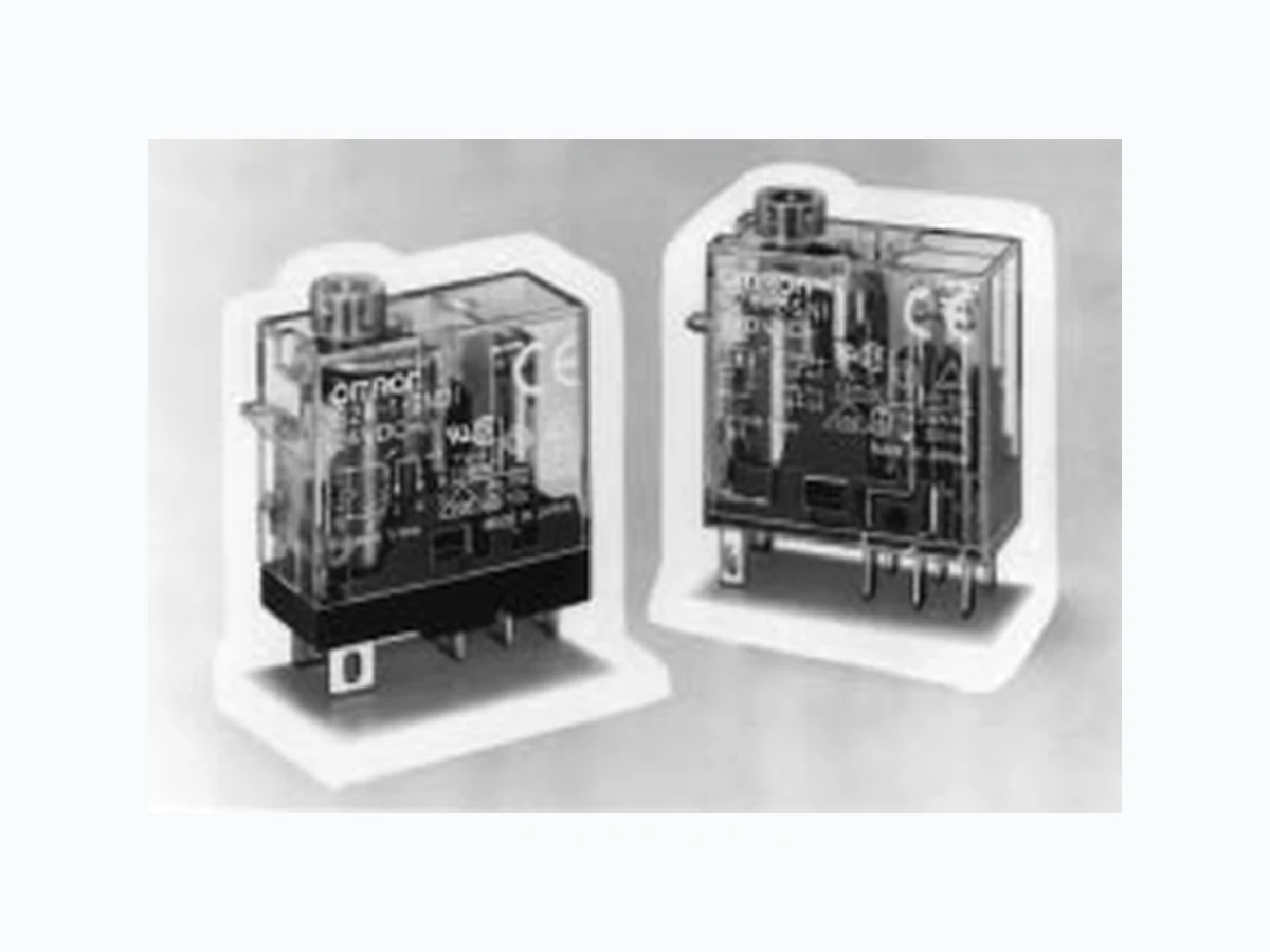
General-purpose Relay G2RS The New-generation General-purpose Relay Reliable and unique test button models now available. High switching capacity (1-pole: 10 A) Highly functional socket also available. Space-saving (29 (H) x 13 (W) x 29 (D)) Conforms to UL508, CSA22.2, VDE0435 (C250 insulation grade). 8-mm creepage distance / 8-mm air distance RC+EW
Ordering Information
Coil ratings Contact formC ass ca o eg ee o protection Co a gs SPST-NO SPDT DPST-NO DPDT Plug-in ti l General-purpose Unsealed AC/DC --- G2R-1-S --- G2R-2-Sug terminal LED indicator U sea ed C/ C --- G2R-1-SN --- G2R-2-SN LED indicator with test button --- G2R-1-SNI --- G2R-2-SNI Diode DC --- G2R-1-SD --- G2R-2-SD LED indicator and diode C --- G2R-1-SND --- G2R-2-SND LED indicator and diode with test button --- G2R-2-SNDI --- G2R-2-SNDI Plug-in ti l General-purpose AC/DC G2R-1A3-S G2R-13-S --- ---ug terminal (Twin LED indicator C/ C G2R-1A3-SN G2R-13-SN --- ---(Tw in crossbar contact) LED indicator and diode DC G2R-1A3-SND G2R-13-SND --- --- Rated coil voltage Note: When ordering, add the rated coil voltage to the model number. Example: G2R-1A 12 VDC Model Number Legend: G2R - - - 12 34 56 7 1. Relay Function None:General-purpose 2. Number of Poles 1: 1 pole 2: 2 poles 3. Contact Form None:SPDT A: SPST-NO 4. Contact Type None:Single 3: Bifurcated crossbar 5. Terminals S: Plug-in 6. Classification None:General-purpose N: LED indicator D: Diode ND: LED indicator and diode I: T est button 7. Rated Coil Voltage
Accessories (Order Separately) Connecting Sockets Number of poles Applicable relay model Track/surface Back mounting socket mounting socket Terminals Model 1 pole G2R-1-S(N)(D)(ND)(NI)(NDI)P2RF-05-E PCB terminals P2R-05P, P2R-057P G2R-13-S (G2R-1A3-S) P2RF-05 Solder terminals P2R-05A 2 poles G2R-2-S(N)(D)(ND)(NI)(NDI)P2RF-08-E PCB terminals P2R-08P, P2R-087P P2RF-08 Solder terminals P2R-08A Note: See Dimensions for details on socket size. Mounting Tracks Applicable socket Description Model Track connecting socket Mounting track 50 cm (/C0527) x 7.3 mm (t): PFP-50N 1 m (/C0527) x 7.3 mm (t): PFP-100N 1 m (/C0527) x 16 mm (t): PFP-100N2 End plate PFP-M Spacer PFP-S Back connecting socket Mounting plate P2R-P* *Used to mount several P2R-05A and P2R-08A Connecting Sockets side by side. Specifications Coil Ratings Rated voltage 12 VAC 24 VAC 100/ (110) VAC
120 VAC 200/
(220) VAC
220 VAC 230 VAC 240 VAC
Rated current* 50 Hz 93 mA 46.5 mA 11 mA 9.3 mA 5.5 (4.0) mA 5.1 mA 4.7 (3.7) mA 4.7 mA 60 Hz 75 mA 37.5 mA 9/ (10.6) mA 7.5 mA 4.5 (5.3) mA 4.1 mA 3.8 (3.1) mA 3.8 mA Coil resistance* 65 Ω 260 Ω 4,600 Ω 6,500 Ω 20,200 (25,000) Ω 25,000 Ω 26,850 (30,000) Ω 30,000 Ω (H) (ref. value)Armature ON 0.39 1.55 26.84 42 102 117 124 131 Must operate voltage 80% max. of rated voltage Must release voltage 30% max. of rated voltage Max. voltage 110% of rated voltage Power consumption Approx. 0.9 VA at 60 Hz (approx. 0.7 VA at 60 Hz) Note: 1. Rated voltage of bifurcated crossbar contact type: 100/(110) VAC, 200/(220) VAC, 230 VAC (Approx. 0.7 VA at 60 Hz) 2. Depending on the type of Relay, Some Relays do not have coil specifications. Contact your OMRON representative for more de- tails. Rated voltage 5 VDC 6 VDC 12 VDC 24 VDC 48 VDC 100 VDC Coil resistance* 47 Ω 68 Ω 275 Ω 1,100 Ω 4,170 Ω 18,860 Ω Must operate voltage 70% max. of rated voltage Must release voltage 15% min. of rated voltage Max. voltage 110% of rated voltage Power consumption Approx. 0.53 W Note: Rated voltage of bifurcated crossbar contact type: 12 VDC, 24 VDC
Number of poles 1 pole 2 poles Load Resistive load (cosφ = 1) Inductive load (cosφ = 0.4; L/R = 7 ms) Resistive load (cosφ = 1) Inductive load (cosφ = 0.4; L/R = 7 ms) Rated load 10 (1) A at 250 VAC; 10 (1) A at 30 VDC
7.5 A at 250 VAC;
5 A at 30 VDC
5 A at 250 VAC;
2 A at 250 VAC; 3 A at
30 VDC
Rated carry current 10 (1) A 5 A Max. operating voltage380 VAC, 125 VDC 380 VAC, 125 VDC Max. operating current10 (1) A 5 A Max. switching capacity 2,500 (250) VA, 300 (30) W 1,875 VA, 150 W 1,250 VA, 150 W
500 VA,
Min. permissible load 100 mA at 5 VDC (1 mA at 5 VDC) 10 mA at 5 VDC Note: 1. P level: λ60 = 0.1 x 10⁻⁶/operation 2. ( ): Twin crossbar contact type. Characteristics Standard Relays Item 1 pole 2 poles Contact resistance 30 mΩ max. 50 mΩ max. Operate (set) time 15 ms max. Release (reset) time AC: 10 ms max.; DC: 5 ms max. (w/built-in diode: 20 ms max.) Max. operating frequency Mechanical: 18,000 operations/hr Electrical: 1,800 operations/hr (under rated load) Insulation resistance 1,000 MΩ min. (at 500 VDC) Dielectric strength 5,000 VAC, 50/60 Hz for 1 min between coil and contacts*; 1,000 VAC, 50/60 Hz for 1 min between contacts of same polarity 5,000 VAC, 50/60 Hz for 1 min between coil and contacts*; 3,000 VAC, 50/60 Hz for 1 min between contacts of different polarity 1,000 VAC, 50/60 Hz for 1 min between contacts of same polarity Vibration resistance Destruction:10 to 55 Hz, 1.5-mm double amplitude Malfunction:10 to 55 Hz, 1.5-mm double amplitude Shock resistance Destruction:1,000 m/s2 (approx. 100G) Malfunction:200 m/s2 when energized (approx. 20G); 100 m/s2 when no energized (approx. 10G) Life expectancy Mechanical:AC coil: 10,000,000 operations min.; DC coil: 20,000,000 operations min. (at 18,000 operations/hr) Electrical:100,000 operations min. (at 1,800 operations/hr under rated load) Ambient temperature Operating: –40°C to 70°C (with no icing) Storage: –40 °C to 70°C (with no icing) Ambient humidity Operating: 35% to 85% Storage: 35% to 85% Weight Approx. 17 g (plug-in terminal: approx. 20 g) Note: Values in the above table are the initial values. *2,000 VAC, 50/60 Hz for 1 minute when the P2R-05A or P2R-08A socket is mounted.
UL 508 (File No. E41643) Model Contact form Coil ratings Contact ratings G2R-1-S SPDT 5 to 110 VDC 5 to 240 VAC
10 A, 30 VDC (resistive)
10 A, 250 VAC (general use)
TV 3 (NO t t l )G2R-1A-S SPST-NO , (g ) TV-3 (NO contact only) G2R-2-S DPDT 5 A, 30 VDC (resistive)
5 A, 250 VAC (general use)
TV-3 (NO contact only) CSA 22.2 No.0, No.14 (File No. LR31928) Model Contact form Coil ratings Contact ratings G2R-1-S SPDT 5 to 110 VDC 5 to 240 VAC TV 3 (NO t t l )G2R-1A-S SPST-NO , (g ) TV-3 (NO contact only) G2R-2-S DPDT 5 A, 30 VDC (resistive) TV-3 (NO contact only) SEV (SEV 1025-1, IEC 158-1) Contact form Coil ratings Contact ratings 1 poles 5 to 110 VDC 5 to 240 VAC
10 A, 250 VAC1
5 A, 250 VAC3
10 A, 30 VDC1
2 poles 5 to 240 VAC 5 A, 250 VAC1
2 A, 380 VAC1
5 A, 30 VDC1
TÜV (IEC 255, VDE 0435) Contact form Coil ratings Contact ratings 1 pole 3 to 110 VDC, 6 VAC to 240 VAC (for Standards coil) 10 A, 250 VAC (cosφ = 1.0)
10 A, 30 VDC (0 ms)
5 A, 250 VAC (cosφ =1.0)
5 A, 30 VDC (0 ms)
2.5 A, 250 VAC (cosφ = 0.4) VDE (IEC 255, VDE 0435) Contact form Coil ratings Contact ratings 1 pole 5, 6, 9, 12, 18, 24, 48, 60, 100, 110 VDC 200/(220), 220, 230, 240 VAC 10 A, 250 VAC (cosφ = 1.0) 2 poles 5, 6, 9, 12, 18, 24, 48, 60, 100, 110 VDC 200/(220), 220, 230, 240 VAC 5 A, 250 VAC (cosφ =1.0)
Switching current (A) Switching voltage (V) G2R-2-S Switching voltage (V) Max. Switching Capacity Switching current (A) AC resistive load DC resistive load AC inductive load (cosφ = 0.4) DC inductive load (L/R = 7 ms) AC resistive load DC resistive load DC inductive load (L/R = 7 ms) AC inductive load (cosφ = 0.4) Switching voltage (V) Switching current (A) G2R-13-S, G2R-1A3-S AC inductive load (cosφ = 0.4) DC inductive load (L/R = 7 ms) AC resistive load DC resistive load Plug-in Relays G2R-1-SLife expectancy (x10 operations)3 Switching current (A) G2R-2-S Switching current (A) Life Expectancy 250-VAC/30-VDC resistive load 250-VAC inductive load (cosφ = 0.4) 30-VDC inductive load (L/R = 7ms) 30-VDC inductive load (L/R = 7ms) 250-VAC/30-VDC resistive load 250-VAC inductive load (cosφ = 0.4) 5,000 1,000 500 100 Life expectancy (x10 operations)3 5,000 1,000 500 100 Switching current (A) Life expectancy (x10 operations)3 G2R-13-S, G2R-1A3-S 250-VAC/30-VDC resistive load 250-VAC (cosφ = 0.4)/30-VDC (L/R = 7 ms) inductive load 10,000 7,000 5,000 3,000 1,000 700 500 300 100 Ambient temperature (°C) Note: The maximum voltage refers to the maximum value in a varying range of operating power voltage, not a continuous voltage. Maximum voltage (%) Ambient Temperature vs Maximum Voltage DC coil AC coil
Note: 1. All units are in millimeters unless otherwise indicated. 2. Orientation marks are indicated as follows: SPDT Relays G2R-1-S, G2R-1-SD, G2R-1-SN, G2R-1-SND, G2R-1-SNI, G2R-1-SNDI G2R-13-S, G2R-13-SD, G2R-13-SN, G2R-13-SND Terminal Arrangement/Internal Connections (Bottom View) DPDT Relays G2R-2-S, G2R-2-SD, G2R-2-SN, G2R-2-SNI, G2R-2-SNDI G2R-2-SND Relays with Plug-in Terminals G2R-1-S, G2R-13-S G2R-1-SN, G2R-1-SNI, G2R-13-SN (AC) G2R-1-SN, G2R-1-SNI, G2R-13-SN (DC) G2R-1-SD, G2R-13-SD (DC) G2R-1-SND, G2R-1-SNDI, G2R-13-SND (DC) Terminal Arrangement/Internal Connections (Bottom View) G2R-2-S G2R-2-SN G2R-2-SNI (AC) G2R-2-SN G2R-2-SNI (DC) G2R-2-SD (DC) G2R-2-SND G2R-2-SNDI (DC) 29 max. 2.5 29 max. 0.5 4.75 13 max. Three 0.9 x 3 el- liptic holes 7.5 5.2 5.2 17.5 29 max. 2.5 28 max. 0.5 2.6 13 max. 7.5 19.4 8.9 4 32 4 32 4 32 4 32 4 32+ 8 6 57 3 42 1 8 6 57 3 42 8 6 57 3 42 8 6 57 3 42 8 6 57 3 42 *This terminal is SPDT only. *Average value *Average value (28.6)* (28.5)* (12.7)* (28.2)* (27.0)* (12.5)* (After confirming coil polarity, wire correctly.) (Except G2R-1-S, G2R-13-S) (After confirming coil polarity, wire correctly.) 29 max. 4.1 max. 13 max. 7.3 max. 29 max. 29 max. 4.1 max. 13 max. 7.3 max. 29 max.
(for Surface Mounting) Terminal Arrangement P2RF-08 7 Five M3.5 x 8 71.5 max. 19.5 max. 4-dia. holes 35.5 19.5 30 max. 54 max. 4.2-dia. hole 30±0.05 M3 or 3.2-dia. hole 71.5 max. 4 19.5 max. Eight M3.5 x 8 4-dia. holes 35.5 19.5 30 max. 54 max. 4.2-dia. hole 30±0.05 M3 or 3.2-dia. hole Mounting Holes (for Surface Mounting) Terminal Arrangement Track/Surface Mounting Sockets P2RF-05-E Mounting Holes (for Surface Mounting) Terminal Arrangement (Top View) 3.2-dia. hole or 3.5-dia. hole M3.5 screw 85.5 max. 3.5-dia. hole 16.0 max. 59 max. 48 max. 39.5 35.5 11.5 Note: Pin numbers in parentheses apply to DIN standard. 61 max. (11) (12) (14) (A1) (A2) 39.5±0.1 P2RF-08-E Terminal Arrangement (Top View) 85.5 max. 2 1.5 M3 screw 3.5-dia. hole 16.0 max. 63.0 max. 48.0 max. 39.5 35.5 11.5 61.0 max. Mounting Holes (for Surface Mounting) 3.2-dia. hole or 3.5-dia. hole 39.5±0.1 (A1) (A2) (21) (22) (24) (11) (12) (14)
P2R-05P (1-pole) 1 47 4.5 3.5 1.2 1.5 36 max. 14.5 max. 35.5 max. Tolerance: ±0.1 4.5 Five 1.6-dia. holes (5) Mounting HolesTerminal Arrangement P2R-08P (2-pole) 4 70.3 2.8 1.5 7.5 36 max.Terminal plate thickness: 0.3 14.5 max. 35.5 max. 7.5 Eight 1.3-dia. holes (4.3) Mounting HolesTerminal Arrangement P2R-05A (1-pole) Panel Cutout Terminal Arrangement P2R-08A (2-pole) 1.20.3 6.7 3.8 16.7 5 Five 3 x 1.8-dia. holes 36 max.Terminal plate thickness: 0.3 14.5 max. 35.5 max. 1.20.3 36 max.Terminal plate thickness: 0.3 14.5 max. 35.5 max. 2.8 2.8 2.6 Eight 3 x 1.2-dia. holes 7.5 13.6±0.1 30.5±0.2 Recommended thickness of the panel is 1.6 to 2.0 mm
Mounting Height of Relay with Socket G2R Relay P2R-_P Socket 30 G2R Relay P2R-_A Socket Mounting Tracks PFP-100N, PFP-50N PFP-100N2 It is recommended to use a panel 1.6 to 2.0 mm thick. L: Length 1 m PFP-100N 50 cm PFP-50N 1 m PFP-100N2 End Plates PFP-M Spacers PFP-S 4.5 15 25 25 25 25 * 10 10 L 7.3±0.15 35±0.3 27±0.15 4.5 15 25 25 25 25 15 10 10 L 35±0.3 27 24 29.2 1 1.5 11.5 10M4 x 8 pan head screw 6.2 1.8 35.5 35.3 1.8 1.3 4.8 44.3 34.8 16.5 Mounting Plates P2R-P R2.25 10 elliptic holes 4.5 13.6 3.4 30.549 42±0.1 Square hole 72±0.2 t = 1.6 mm
C&C Components Division H.Q. Relay Division 28th Fl., Crystal Tower Bldg., 1-2-27, Shiromi, Chuo-ku, Osaka 540-6028 Japan Phone: (81)6-949-6125 Fax: (81)6-949-6134 ALL DIMENSIONS SHOWN ARE IN MILLIMETERS. To convert millimeters into inches, multiply by 0.03937. To convert grams into ounces, multiply by 0.03527. Cat. No. J114-E1-1AIn the interest of product improvement, specifications are subject to change without notice. Printed in Japan 1098-4M (0898) a