
G24AW305111 ETC2
Document overview
- Manufacturer or author: Provided By www.digicamel.com(FREE DATASHEET DOWNLOAD SITE)
- PDF pages: 19
Technical content
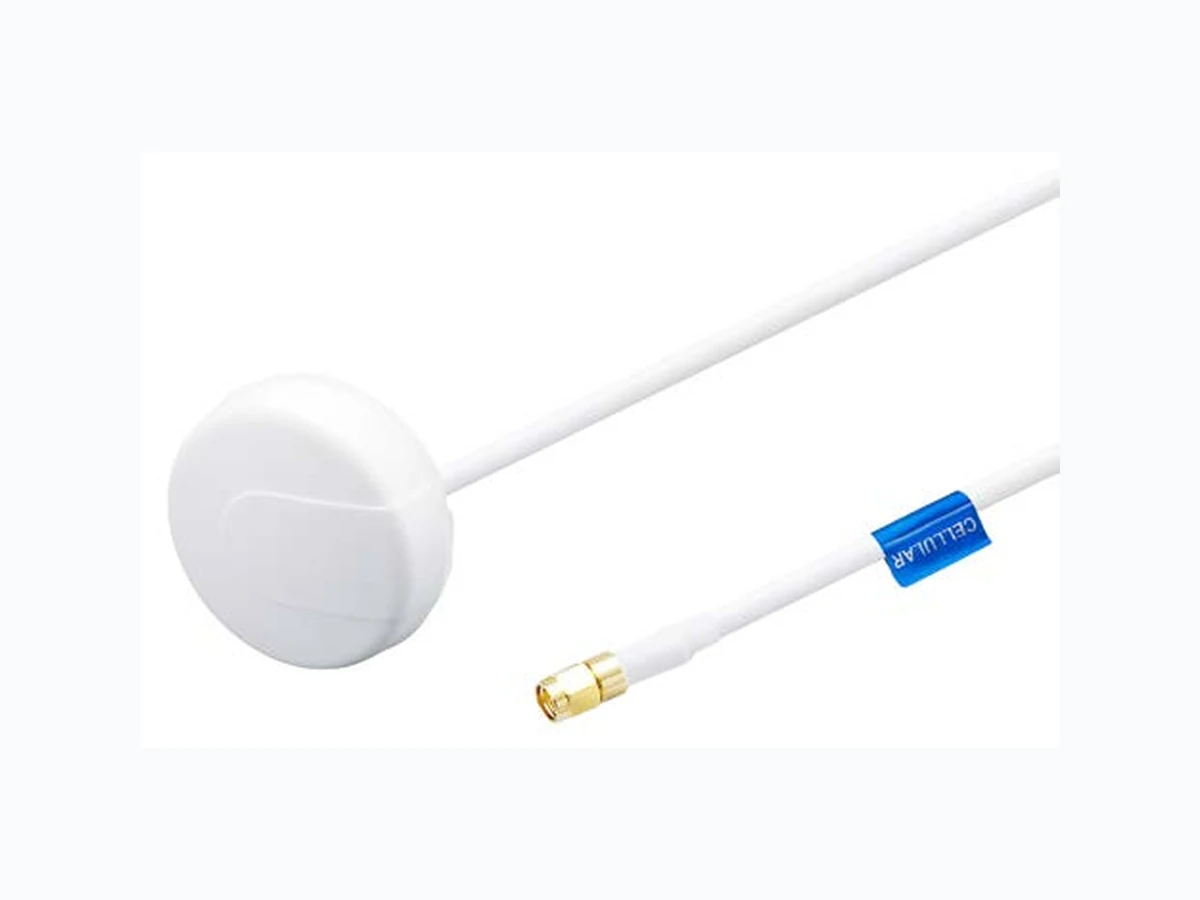
SPE-13-8-044/A/SS | page 1 of 19 G24.A.W.305111 Specification Part No. G24.A.W.305111 Product Name Ultima G24 Ultima Series – Super Low Profile Penta Band Cellular 800~960/1710~220MHz Antenna Screw Mount GSM/GPRS/CDMA/HSPA (Permanent mount) Feature Height 19.6mm (0.77”) Diameter 55mm (2.16”) Heavy duty Screw Mount UV and vandal resistant ABS housing and thread IP67 compliant Standard is 3 meter low loss cable CFD200 SMA(M) White Housing Cables and Connectors Customizable ROHS Compliant
SPE-13-8-044/A/SS | page 2 of 19 G24.W Ultima Series Cellular Antenna is an extremely low profile 2G/3G 800MHz to 2200MHz cellular antenna solution for professional telematics applications. Suitable for GSM/GPRS/CDMA applications worldwide, at only 19.6mm (0.77”) in height it is the lowest profile antenna in the market, with a diameter of only 55 mm (2.16”). It works well when mounted on both metal and non-metal. In other words it does not need a metal ground-plane to attach to, to radiate, something that competitor antennas all need. Durable UV ABS housing, thread and nut is resistant to vandalism and direct attack. The IP67 waterproof robust plastic body makes it extremely light, economical for shipping and minimum weight impact on vehicles. This also makes it ideal for use in humid environments such as water pits or marine applications as there are no metal parts to corrode. The closed cell foam with double-sided adhesive provides a permanent waterproof seal and can adjust to different curvatures, stopping water from leaking under the antenna into the mounting hole. Lowest loss PTFE cable is used for maximum gain and reduced noise entry through the cable. Also available in Black. 1. Introduction Cellular Frequency (MHz) 824 ~ 896 880 ~ 960 1710 ~ 1880 1850 ~ 1990 1710 ~ 2170 Peak Gain (dBi) Average Gain (dBi) Efficiency (%) 2. Specification
SPE-13-8-044/A/SS | page 3 of 19 2. Specification Cellular Impedance 50Ω Polarization Linear Radiation Pattern Omni Mechanical Dimensions Ø 55±2mm , Height 30±2 mm, Profile 19.6mm Ø 2.16”; Height 1.18”; Profile 0.77” Cable Type CFD200 Cable Length 3000±30mm (9’ 101⁄8”±1.18”) Casing ABS Connector SMA Male Environmental Temperature Range -40°C to 85°C Waterproof IP-67 Thermal Shock 100 cycles -40°C to +80°C Shock (drop test) 1m drop on concrete 6 axes Humidity Non-condensing 65°C 95% RH
SPE-13-8-044/A/SS | page 4 of 19
3.1 Cellular Antenna SWR
3.2 Antenna Efficiency
500 1000 1500 2000 2500 3000 (MHz) 800 1000 1200 1400 1600 1800 2000 2200 (MHz) Free Space on 10 x 10cm Ground Plane on 20 x 20cm Ground Plane on 30 x 30cm Ground Plane (%) SWR 3. Antenna Characteristics Free Space on 10 x 10cm Ground Plane on 20 x 20cm Ground Plane on 30 x 30cm Ground Plane
SPE-13-8-044/A/SS | page 5 of 19
3.3 Peak Gain
3.4 Antenna Gain
-10 -10 -12 -14 -16 -18 -20 800 1000 1200 1400 1600 1800 2000 2200 (MHz) 800 1000 1200 1400 1600 1800 2000 2200 (MHz) Free Space on 10 x 10cm Ground Plane on 20 x 20cm Ground Plane on 30 x 30cm Ground Plane (dBi) (dBi) Free Space on 10 x 10cm Ground Plane on 20 x 20cm Ground Plane on 30 x 30cm Ground Plane
SPE-13-8-044/A/SS | page 6 of 19 4. Antenna Radiation Pattern (Free Space)
4.1 Antenna Setup (Free Space)
SPE-13-8-044/A/SS | page 7 of 19
4.2.1 X-Z plane (dBi) (Free Space)
4.2 Radiation Pattern (Free Space)
SPE-13-8-044/A/SS | page 8 of 19
4.2.2 X-Z plane (dBi) (Free Space)
SPE-13-8-044/A/SS | page 9 of 19 5. Antenna Radiation Pattern (10*10mm)
5.1 Antenna Setup (10*10mm Ground Plane)
SPE-13-8-044/A/SS | page 10 of 19
5.2.1 X-Y plane (dBi) (10*10mm Ground Plane)
5.2 Radiation Pattern (10*10mm Ground Plane)
SPE-13-8-044/A/SS | page 11 of 19
5.2.2 X-Z plane (dBi) (10*10mm Ground Plane)
SPE-13-8-044/A/SS | page 12 of 19 6. Antenna Radiation Pattern – (20*20mm Ground Plane)
6.1 Antenna Setup (20*20mm Ground Plane)
SPE-13-8-044/A/SS | page 13 of 19
6.2.1 X-Y plane (dBi) (20*20mm Ground Plane)
6.2 Radiation Pattern (20*20mm Ground Plane)
SPE-13-8-044/A/SS | page 14 of 19
6.2.2 X-Z plane (dBi) (20*20mm Ground Plane)
SPE-13-8-044/A/SS | page 15 of 19 7. Antenna Radiation Pattern – (30*30mm Ground Plane)
7.1 Antenna Setup (30*30mm Ground Plane)
SPE-13-8-044/A/SS | page 16 of 19
7.2.1 X-Y plane (dBi) (20*20mm Ground Plane)
7.2 Radiation Pattern (20*20mm Ground Plane)
SPE-13-8-044/A/SS | page 17 of 19
7.2.2 X-Z plane (dBi) (20*20mm Ground Plane)
SPE-13-8-044/A/SS | page 18 of 19 8. Drawing Name Material Finish QTY
1 Housing Top ABS White 1
2 Housing bottom ABS White 1
3 M20 Nut ABS White 1
4 Silicon Rubber Silicon Rubber Black 1
5 Foam DP3060+3M9448 White 1
6 Heat Shrink Tube PE Black 1
7 Cellular Label Coated Paper Blue 1
XX Cable Length 3000 ± 60mm 1 YY Cable Type CFD 200 Black 1 ZZ Connector Type SMA(M) Gold 1
SPE-13-8-044/A/SS | page 19 of 19 9. Packaging Taoglas makes no warranties based on the accuracy or completeness of the contents of this document and reserves the right to make changes to specifications and product descriptions at any time without notice. Taoglas reserves all rights to this document and the information contained herein. Reproduction, use or disclosure to third parties without express permission is strictly prohibited. Copyright © Taoglas Ltd. UNLESS OTHER SPECIFIED TOLERANCES ON: ANGLES=± HOLEDIA =± SCALE: xxxx UNIT :mm DRAWN BY: Jason CHECKED BY: Wayne DESIGNED BY: Wayne APPROVED BY: Wayne TITLE: G24.A Antenna Assembly DOCUMENT G24.A.W.305111 PAGE REV. NO. B ISO NO: PSP-12-8-0252 PAGE 7 OF 7 5 包裝規格 5.1 每個小 PE 袋放置 1 天線 【1pcs antenna per small PC bag】 5.2 每個箱子放置 40 個小 PE 袋,如下圖所示 【40 small PE bags per box】 5.3 封口時須注意不可壓到天線,裝入需平整不可雜亂 Antenna should be placed flat and neat in the PE bag. Hot seal the PE bag without pressing or damage the antenna】 5.4 清點每箱數量不可短缺 【Double check the quantity in each box】 G24.A 小 PE 袋 箱子 1pcs antenna per small PC bag 40 small PE bags per box