
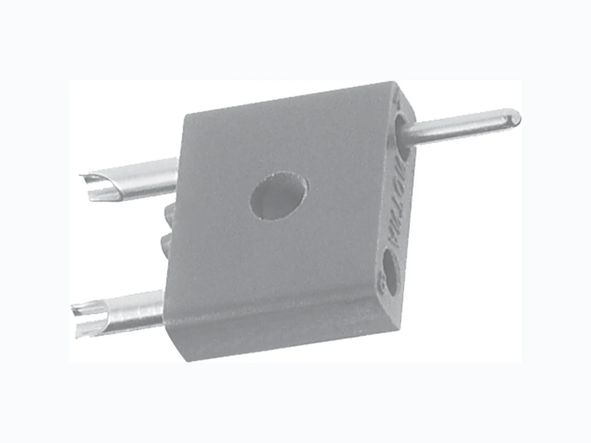
G20 VISHAY
Document overview
- Manufacturer or author: Provided By www.digicamel.com(FREE DATASHEET DOWNLOAD SITE)
- PDF pages: 2
Technical content
Document Number: 36020 For technical questions contact: connectors@vishay.com www.vishay.com Revision: 14-Feb-07 22 Rack and Panel Connectors Side Mount G20 Vishay Dale
APPLICATIONS
Broad - limited only by those applications requiring physical, electrical and/or materials sp ecifications exceeding those indicated. ELECTRICAL SPECIFICATIONS Breakdown Voltage (Contact to Contact): At sea level: 5000 VRMS At 70 000 feet [21 336 meters]: 650 VRMS Current Rating: 7.5 A
FEATURES
- Body components available with any desired pin and socket combination Contacts float in molding to aid in aligning and in withstanding vibration Polarization accomplished by reversed pin and socket combination Barriers for increased creepage distance Thru hold permits use of building block technique or flat mounting MATERIAL SPECIFICATIONS Standard Body: Glass-filled diallyl phthalate per ASTM D 5948-96 green, flame retardant Pin Contacts: Brass Socket Contacts: Phosphor bronze Contact Plating: Gold, 10 micro-inches PHYSICAL SPECIFICATIONS Minimum Creepage Path between Contacts: 0.25" [6.35 mm] Minimum Air Space between Contacts: 0.19" [4.76 mm] Maximum Wire Size: #20 AWG G20S-A G20P-A DIMENSIONS in inches [millimeters] G20P-A 0.750 [19.05] 0.180 [4.57] 0.218 [5.54] 0.040 Dia. [1.02] Socket Contact “C” Ring 0.359 [9.13] 0.440 [11.1] 0.265 [6.73] Body A B 0.125 [3.17] 0.093 [2.36] Dia. Pin Contact, 0.046 [1.17] Dia. Solder Cup for #20 AWG Wire Typ. G20S-A 0.125 [3.17] 0.440 [11.1] Body 0.265 [6.73] A B 0.359 [9.13] 0.093 [2.36] Dia. 0.218 [5.54] Pin Contact “C” Ring 0.750 [19.05] 0.180 [4.57] 0.200 [5.08] 0.040 [1.02] Dia. Socket Contact 0.046 [1.17] Dia. Solder Cup for #20 AWG Wire Typ.
ORDERING INFORMATION
EXAMPLE 1: G20P-A = Connector with pin contact in position “A” and socket contact in position “B” G20 MODEL G20 - Side Mount with 2 positions for #20 AWG contacts AB B A CONTACT VARIATIONS Designates pin contact positions in a G20P connector or socket contact positions in a G20S connector EXAMPLE 3: G20P-AB = Connector with pin contacts in both positions (would mate with G20S-AB) S P BODY STYLE P - Pin style body. S - Socket style body. These designators are used to identify mating connectors. If designator 3 is the same, a connector designated G20P will mate with a connector designated G20S EXAMPLE 2: G20S-A = Connector with socket contact in position “A” and pin contact in position “B” (would mate with example 1 at left)
www.vishay.com Vishay Revision: 01-Jan-2022 1 Document Number: 91000 Disclaimer ALL PRODUCT, PRODUCT SPECIFICATIONS AND DATA AR E SUBJECT TO CHANGE WITH OUT NOTICE TO IMPROVE RELIABILITY, FUNCTION OR DESIGN OR OTHERWISE. Vishay Intertechnology, Inc., its affiliates, agents, and employee s, and all persons acting on it s or their behalf (collectivel y, “Vishay”), disclaim any and all liability for any errors, inaccuracies or incompleteness contained in any datasheet or in any other disclosure relating to any product. Vishay makes no warranty, representation or guarantee regarding the suitability of the products for any particular purpose or the continuing production of any product. To the maximum extent permitted by applicable law, Vishay disclaims (i) any and all liability arising out of the application or use of any product , (ii) any and all liability, including without limitation specia l, consequential or incidental damages, and (iii) any and all implied warranties, incl uding warranties of fitness for particular purpose, non-infringement and merchantability. Statements regarding the suitability of pro ducts for certain types of applications are based on Vishay's knowledge of typical requirements that are often placed on Vishay products in ge neric applications. Such statements are not binding statements about the suitability of products for a particular application. It is the customer's responsibility to validate that a particular product with the properties described in the product specification is suitable for use in a particular application. Parameters provided in datasheets and / or specificat ions may vary in different applications and performance may vary over time. All operating parameters, including typical parameters, must be validated for each customer application by the customer's technical experts. Product specifications do not expand or otherwise modify Vishay's terms and conditions of purchase, including but not limited to the warranty expressed therein. Hyperlinks included in this datasheet may direct users to third-party websites. These links are provided as a convenience and for informational purposes only. Inclusion of these hyperlinks does not constitute an endorsement or an approval by Vishay of any of the products, services or opinions of the corporation, organization or individual associated with the third-party website. Vishay disclaims any and all liability and bears no responsibility for the accuracy, legality or content of the third-party web site or for that of subsequent links. Except as expressly indicated in writing, Vishay products are not designed for use in medical, life-saving, or life-sustaining applications or for any other application in which the failure of the Vishay product could result in personal injury or death. Customers using or selling Vishay products not expressly indicated for use in such applications do so at their own risk. Please contact authorized Vishay personnel to obtain written terms and conditions regarding products designed for such applications. No license, express or implied, by estoppel or otherwise, to any intellectual property rights is granted by this document or by any conduct of Vishay. Product names and markings noted herein may be trademarks of their respective owners. © 2022 VISHAY INTERTECHNOLOGY, INC. ALL RIGHTS RESERVED