

 Download PDF
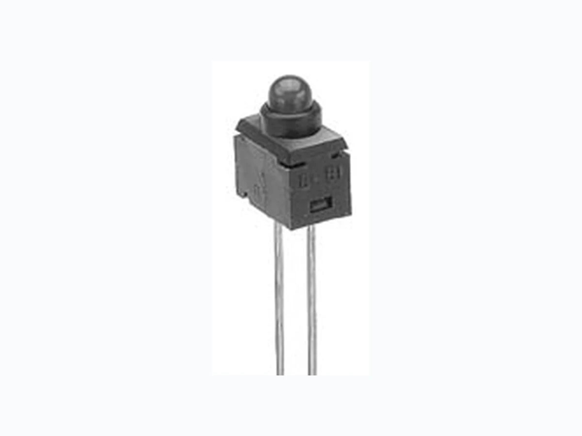
G01PC NKK
Document overview
- PDF pages: 1
Technical content
Page 1
Complement to G Switches G Indicators
TYPICAL INDICATOR ORDERING EXAMPLE
G01
P
C
Red LED
DESCRIPTION FOR TYPICAL ORDERING EXAMPLE
G01PC
PC TERMINALS
LED COLORS
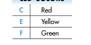
P Straight V Vertical
Straight PC Terminals
LED COLORS & SPECIFICATIONS
| LED is colored in OFF state Color | C Red | E Yellow | F Green |
| Forward Peak Current I FM | 30mA | 30mA | 30mA |
| Continuous Forward Current I F | 20mA | 20mA | 20mA |
| Forward Voltage V F | 2.0V | 2.0V | 2.1V |
| Reverse Peak Voltage V RM | 5V | 5V | 5V |
| Current Reduction Rate Above 25°C ∆I F | 0.40mA/°C | 0.40mA/°C | 0.40mA/°C |
| Ambient Temperature Range | –25°C ~ +85°C | ||
| Electrical specifications are determined at a basic temperature of 25°C. If the source voltage is greater than the LED’s rated voltage, a ballast resistor must be connected in series with the LED. That ballast resistor value can be calculated by using the formula shown in the Supplement section. | |||
TYPICAL INDICATOR DIMENSIONS
Straight PC
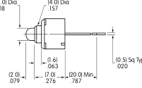
(3.0) Dia
LED + Mark
.118
(2.54) .100
(7.0) .276
(0.8) Dia Typ .031
Slot
(1.27) Typ
(4.5)
.050
.177
G01PC
Vertical PC
(0.4)
(4.0) Dia (3.0) Dia
LED + Mark
.016
.157 .118
(2.54) .100
(7.4) .292
(5.08) .200
(15.5) Min .610
(0.8) Dia Typ
Slot
.031
(0.5) Sq Typ
(2.6)
(0.4) Dia Typ
.020
.102
.016
(1.27) Typ
(5.08) (1.6)
(2.54)
.050
.200 .063
.100
(4.5)
(2.0) (7.68)
(5.3)
.177
.079 .302
.209
G01VC
These indicators have anode and cathode terminals along with 2 support pins.
NKK Switches • email: sales@nkkswitches.com • Phone (480) 991-0942 • Fax (480) 998-1435 • www.nkkswitches.com
03-07