

 Download PDF
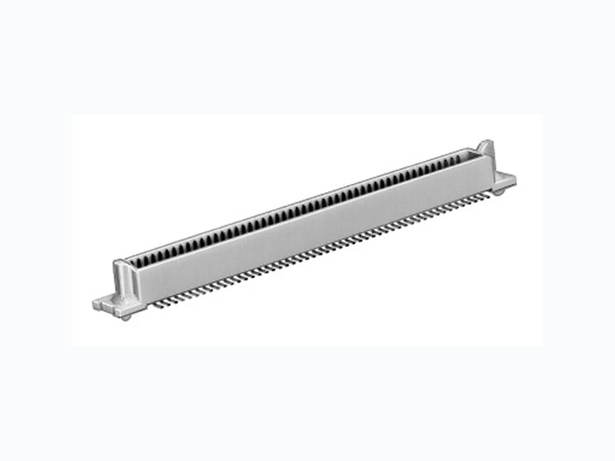
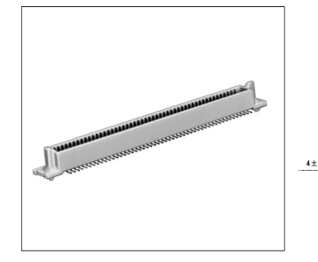
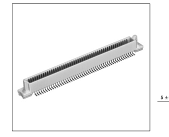
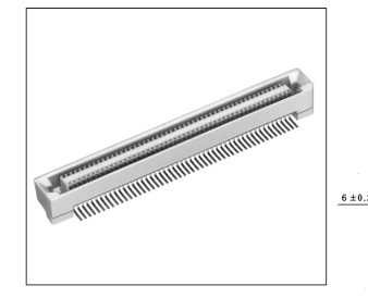
FX6-20P-0.8SV HIROSE
Document overview
- PDF pages: 13
Technical content
Page 1

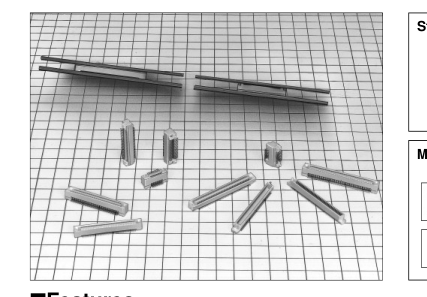
IFeatures
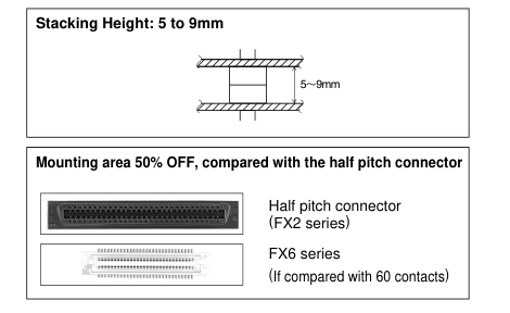
1. Stacking Height 5 to 9mm
The board to board stacking height can be set at every millimeter between 5 and 9mm.
2. Effective Contact Length 1.7mm
Despite the low profile type connector, the connector has the
4. Automatic Mounting
The standard packaging specification specifies the stick package, considering the automatic mount, while the emboss package can also correspond to the connector with less than 80 contacts. (However, the product is limited to 80 contacts.)
1.7mm long effective contact length and provides a margin 5. SMT Coplanarity
The lead coplanarity on the SMT soldered area is maintained
sufficient to contact.
with the high accuracy of less than 0.1mm.
3. Mating Guide
The self-alignment for mating action exhibits a high guide level at ± 1mm, and makes the mating process easier by providing the guide rib.
IApplications
Note PC, business equipments such as handy terminals, and other equipment which require miniaturization or light-weight.
IProduct Specifications
Operating Temperature Range -55ç to +85ç Note 1.
Storage Temperature Range -10ç to +60ç Note 2.
Current rating 0.5A
Rating
Voltage rating 100V AC Operating Humidity Range 40% to 80%
Storage Humidity Range 40% to 70%
| Item | Specification | Condition |
|---|---|---|
| 1. Insulation Resistance | 100M ohms min | 250V DC |
| 2. Withstanding voltage | No flashover or insulation breakdown. | 300V AC/1 minute |
| 3. Contact Resistance | 40m ohms max. | 100mA |
| 4. Vibration | No electrical discontinuity of 1µs or more | Frequency: 10 to 55 Hz, single amplitude of 0.75 mm, 2 hours in each of the 3 directions. |
| 5. Humidity (Steady state) | Contact resistance: 50m ohms max. Insulation resistance: 100m ohms min. | 96 hours at temperature of 40ç and humidity of 90% to 95% |
| 6. Temperature Cycle | Contact resistance: 50m ohms max: Insulation resistance: 100m ohms min. | (-55ç: 30 minutes 15 to 35ç: 2 to 3 minutes (-85ç: 30 minutes 15 to 35ç: 2 to 3minutes)5 cycles |
| 7. Durability (Mating/un-mating) | Contact resistance: 50m ohms max. | 100 cycles |
| 8. Resistance to Soldering heat | No deformation of components affecting performance. | Reflow: At the recommended temperature profile |
| Manual soldering: 300ç for 3 seconds |
Note 1: Includes temperature rise caused by current flow. Note 2: The term "storage" refers to products stored for long period of time prior to mounting and use. Operating Temperature Range and Humidity range covers non conducting condition of installed connectors in storage, shipment or during transportation.
A213
Page 2
IMaterial
| Part | Material | Finish | Remarks | |
|---|---|---|---|---|
| Insulation | PPS | Light brown | UL94V-0 | |
| Header Contact | Phosphor bronze | Contact area | Gold plated | ———— |
| Receptacle Contact | Lead area | Tin-lead plated | ———— | |
Note : The black dots on the insulater will not affect performance.
IOrdering Information
FX6 (A) - \* P - 0.8 SV 1 (21)
1 2 3 4
5 6 7 8
| q Series Name: FX6 y Contact type SV: Board vertical type w Blank: With boss u Product Height VariableBlank : Standard, 1: +1mm A : Without boss 2 : +2mm e Number of Contacts : 20,40,50,60,80,100 i Packaging Style r Connector Type Blank : Stick packaging (No pick & place tape) P: Header (21) : Stick packaging (Pick & place tape) S: Receptacle (22) : Embossed tape packaging (No pick & place tape) t Contact Pitch: 0.8mm (23) : Embossed tape packaging (Pick & place Stick tape) IStacking Height Variation Unit: mm FX6(A)-*S-0.8SV FX6(A)-*S-0.8SV2 FX6(A)-πP-0.8SV 5 7 9 FX6(A)-πP-0.8SV1 6 8 to 5 FX6(A)-πP-0.8SV2 7 9 (* indicates 20, 40, 50, 60, 80, and 100 contacts.) IPackaging Type | |||||||
|---|---|---|---|---|---|---|---|
| Packaging Type | Number of Contacts | 20 contacts | 40 contacts | 50 contacts | 60contacts | 80 contacts | 100 contacts |
| Stick Packaging | Packaged Product Pieces | 33 pieces | 22 pieces | 19 pieces | 16 pieces | 13 pieces | 11 pieces |
| Sales Unit | Order by doubling the number of pieces contained in the product. (Example) In case of 20 contacts,33 pieces, 66 pieces,... | ||||||
| Embossed Tape Packaging | Tape Width | 24mm | 44mm | 44mm | 44mm | 56mm | |
| Product Pitch | 12mm | ||||||
| Emboss Reel Diameter | FX6(A)_*S-0.8SV ……………………………………………Ø330mm FX6(A)_*P_0.8SV.FX6(A)_*S-0.8SV2 …………………Ø360mm FX6(A)_*P_0.8SV1.FX6(A)_*P-0.8SV2 ………………Ø380mm | ||||||
| Packaged Product Pieces | 1000 pieces packaged per reel | ||||||
| Sales Unit | Per reel | ||||||
| q Series Name: FX6 | y Contact type SV: Board vertical type |
|---|---|
| w Blank: With boss A : Without boss | u Product Height VariableBlank : Standard, 1: +1mm 2 : +2mm |
| e Number of Contacts : 20,40,50,60,80,100 | i Packaging Style Blank : Stick packaging (No pick & place tape) (21) : Stick packaging (Pick & place tape) (22) : Embossed tape packaging (No pick & place tape) (23) : Embossed tape packaging (Pick & place Stick tape |
| r Connector Type P: Header S: Receptacle | |
| t Contact Pitch: 0.8mm |
| FX6(A)-*S-0.8SV | FX6(A)-*S-0.8SV2 | |
| FX6(A)-πP-0.8SV | 5 | 7 |
| FX6(A)-πP-0.8SV1 | 6 | 8 |
| FX6(A)-πP-0.8SV2 | 7 | 9 |
A214
Page 3
With Boss Type
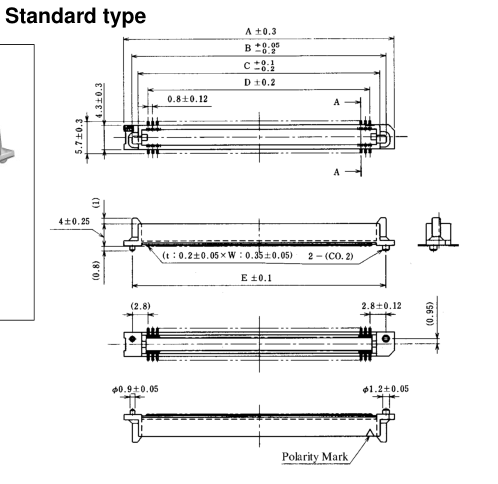
IHeader-Stacking Height: Standard type
BPCB mounting pattern
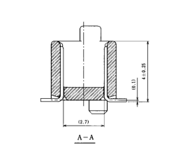
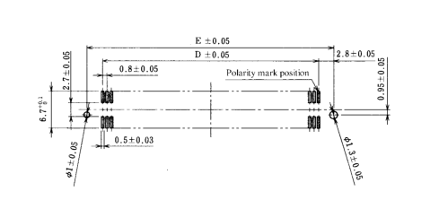
Unit: mm
| Part Number | CL No. | Number of Contacts | A | B | C | D | E |
|---|---|---|---|---|---|---|---|
| FX6-020P-0.8SV | 576-0001-3 | 20 | 15.8 | 12.9 | 10.7 | 07.2 | 12.8 |
| FX6-040P-0.8SV | 576-0003-9 | 40 | 23.8 | 20.9 | 18.7 | 15.2 | 20.8 |
| FX6-050P-0.8SV | 576-0004-1 | 50 | 27.8 | 24.9 | 22.7 | 19.2 | 24.8 |
| FX6-060P-0.8SV | 576-0005-4 | 60 | 31.8 | 28.9 | 26.7 | 23.2 | 28.8 |
| FX6-080P-0.8SV | 576-0007-0 | 80 | 39.8 | 36.9 | 34.7 | 31.2 | 36.8 |
| FX6-100P-0.8SV | 576-0008-2 | 100 | 47.8 | 44.9 | 42.7 | 39.2 | 44.8 |
Note:Determine a quantity of the stick package product for delivery, multiplying the insertion pieces per contact number by an integer. Please make sure that a quantity of the stick package product for delivery is determined per reel (1000 pieces). (Refer to the delivery form item on page A214 for details.)
A215
Page 4
With Boss Type
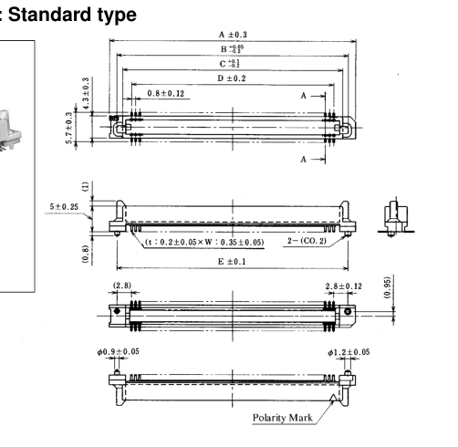
IHeader-Stacking Height: Standard type
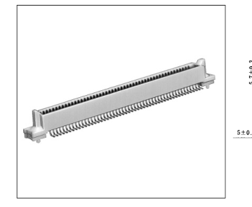
BPCB mounting pattern
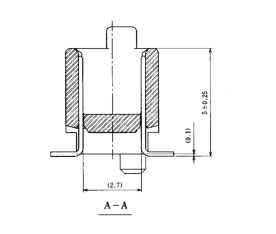
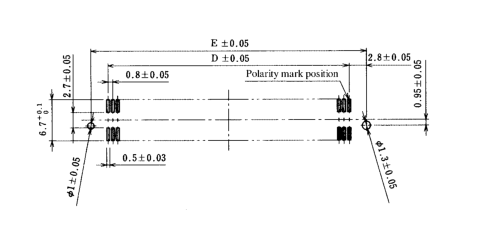
Unit: mm
| Part Number | CL No. | Number of Contacts | A | B | C | D | E |
|---|---|---|---|---|---|---|---|
| FX6-020P-0.8SV1 | 576-0021-0 | 20 | 15.8 | 12.9 | 10.7 | 07.2 | 12.8 |
| FX6-040P-0.8SV1 | 576-0023-6 | 40 | 23.8 | 20.9 | 18.7 | 15.2 | 20.8 |
| FX6-050P-0.8SV1 | 576-0024-9 | 50 | 27.8 | 24.9 | 22.7 | 19.2 | 24.8 |
| FX6-060P-0.8SV1 | 576-0025-1 | 60 | 31.8 | 28.9 | 26.7 | 23.2 | 28.8 |
| FX6-080P-0.8SV1 | 576-0027-7 | 80 | 39.8 | 36.9 | 34.7 | 31.2 | 36.8 |
| FX6-100P-0.8SV1 | 576-0028-0 | 100 | 47.8 | 44.9 | 42.7 | 39.2 | 44.8 |
Note:Determine a quantity of the stick package product for delivery, multiplying the insertion pieces per contact number by an integer. Make sure that a quantity of the stick package product for delivery is determined per reel (1000 pieces). (Refer to the delivery form item on page A214 for details.)
A216
Page 5
With Boss Type
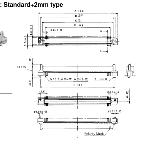
IHeader-Stacking Height: Standard+2mm type
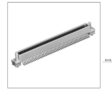
BPCB mounting pattern
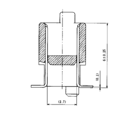
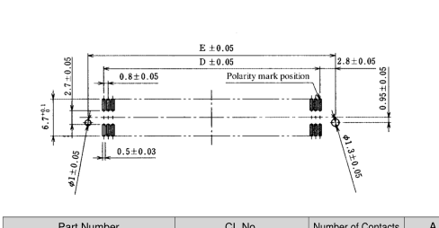
Unit: mm
| Part Number | CL No. | Number of Contacts | A | B | C | D | E |
|---|---|---|---|---|---|---|---|
| FX6-020P-0.8SV2 | 576-0041-8 | 20 | 15.8 | 12.9 | 10.7 | 07.2 | 12.8 |
| FX6-040P-0.8SV2 | 576-0043-3 | 40 | 23.8 | 20.9 | 18.7 | 15.2 | 20.8 |
| FX6-050P-0.8SV2 | 576-0044-6 | 50 | 27.8 | 24.9 | 22.7 | 19.2 | 24.8 |
| FX6-060P-0.8SV2 | 576-0045-9 | 60 | 31.8 | 28.9 | 26.7 | 23.2 | 28.8 |
| FX6-080P-0.8SV2 | 576-0047-4 | 80 | 39.8 | 36.9 | 34.7 | 31.2 | 36.8 |
| FX6-100P-0.8SV2 | 576-0048-7 | 100 | 47.8 | 44.9 | 42.7 | 39.2 | 44.8 |
Note:Determine a quantity of the stick package product for delivery, multiplying the insertion pieces per contact number by an integer. Make sure that a quantity of the stick package product for delivery is determined per reel (1000 pieces). (Refer to the delivery form item on page A214 for details.)
A217
Page 6
With Boss Type
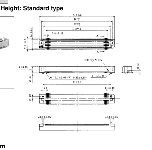
IReceptacle-Stacking Height: Standard type
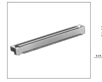
BPCB mounting pattern
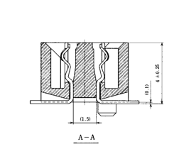
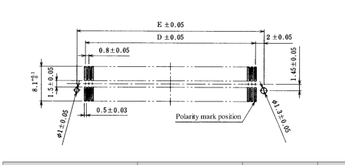
Unit: mm
| Part Number | CL No. | Number of Contacts | A | B | C | D | E |
|---|---|---|---|---|---|---|---|
| FX6-020S-0.8SV | 576-0101-8 | 20 | 15.8 | 12.95 | 10.9 | 07.2 | 11.2 |
| FX6-040S-0.8SV | 576-0103-3 | 40 | 23.8 | 20.95 | 18.9 | 15.2 | 19.2 |
| FX6-050S-0.8SV | 576-0104-6 | 50 | 27.8 | 24.95 | 22.9 | 19.2 | 23.2 |
| FX6-060S-0.8SV | 576-0105-9 | 60 | 31.8 | 28.95 | 26.9 | 23.2 | 27.2 |
| FX6-080S-0.8SV | 576-0107-4 | 80 | 39.8 | 36.95 | 34.9 | 31.2 | 35.2 |
| FX6-100S-0.8SV | 576-0108-7 | 100 | 47.8 | 44.95 | 42.9 | 39.2 | 43.2 |
Note:Determine a quantity of the stick package product for delivery, multiplying the insertion pieces per contact number by an integer. Make sure that a quantity of the stick package product for delivery is determined per reel (1000 pieces). (Refer to the delivery form item on page A214 for details.)
A218
Page 7
With Boss Type
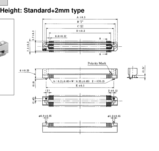
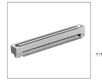
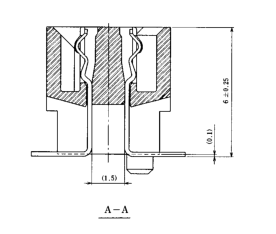
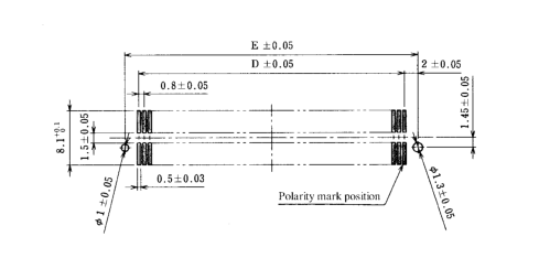
IReceptacle-Stacking Height: Standard+2mm type
BPCB mounting pattern
Unit: mm
| Part Number | CL No. | Number of Contacts | A | B | C | D | E |
|---|---|---|---|---|---|---|---|
| FX6-020S-0.8SV2 | 576-0121-5 | 20 | 15.8 | 12.95 | 10.9 | 07.2 | 11.2 |
| FX6-040S-0.8SV2 | 576-0123-0 | 40 | 23.8 | 20.95 | 18.9 | 15.2 | 19.2 |
| FX6-050S-0.8SV2 | 576-0124-3 | 50 | 27.8 | 24.95 | 22.9 | 19.2 | 23.2 |
| FX6-060S-0.8SV2 | 576-0125-6 | 60 | 31.8 | 28.95 | 26.9 | 23.2 | 27.2 |
| FX6-080S-0.8SV2 | 576-0127-1 | 80 | 39.8 | 36.95 | 34.9 | 31.2 | 35.2 |
| FX6-100S-0.8SV2 | 576-0128-4 | 100 | 47.8 | 44.95 | 42.9 | 39.2 | 43.2 |
Note:Determine a quantity of the stick package product for delivery, multiplying the insertion pieces per contact number by an integer. Make sure that a quantity of the stick package product for delivery is determined per reel (1000 pieces). (Refer to the delivery form item on page A214 for details.)
A219
Page 8
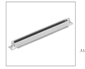
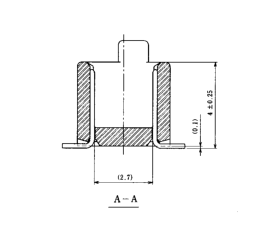
Without Boss Type
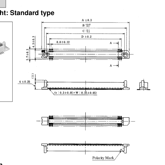
IHeader-Stacking Height: Standard type
BPCB mounting pattern
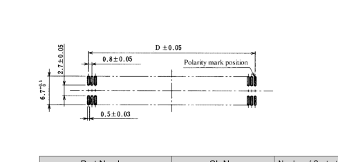
Unit: mm
| Part Number | CL No. | Number of Contacts | A | B | C | D |
|---|---|---|---|---|---|---|
| FX6A-020P-0.8SV | 576-0201-2 | 20 | 15.8 | 12.9 | 10.7 | 07.2 |
| FX6A-040P-0.8SV | 576-0203-8 | 40 | 23.8 | 20.9 | 18.7 | 15.2 |
| FX6A-050P-0.8SV | 576-0204-0 | 50 | 27.8 | 24.9 | 22.7 | 19.2 |
| FX6A-060P-0.8SV | 576-0205-3 | 60 | 31.8 | 28.9 | 26.7 | 23.2 |
| FX6A-080P-0.8SV | 576-0207-9 | 80 | 39.8 | 36.9 | 34.7 | 31.2 |
| FX6A-100P-0.8SV | 576-0208-1 | 100 | 47.8 | 44.9 | 42.7 | 39.2 |
Note:Determine a quantity of the stick package product for delivery, multiplying the insertion pieces per contact number by an integer. Please make sure that a quantity of the stick package product for delivery is determined per reel (1000 pieces). (Refer to the delivery form item on page A214 for details.)
A220
Page 9
Without Boss Type
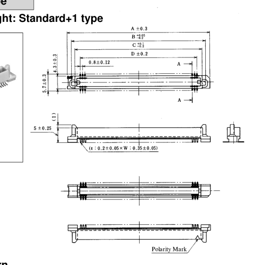
IHeader-Stacking Height: Standard+1 type
BPCB mounting pattern
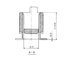
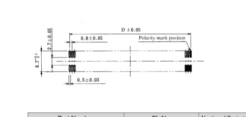
Unit: mm
| Part Number | CL No. | Number of Contacts | A | B | C | D |
|---|---|---|---|---|---|---|
| FX6A-020P-0.8SV1 | 576-0221-0 | 20 | 15.8 | 12.9 | 10.7 | 07.2 |
| FX6A-040P-0.8SV1 | 576-0223-5 | 40 | 23.8 | 20.9 | 18.7 | 15.2 |
| FX6A-050P-0.8SV1 | 576-0224-8 | 50 | 27.8 | 24.9 | 22.7 | 19.2 |
| FX6A-060P-0.8SV1 | 576-0225-0 | 60 | 31.8 | 28.9 | 26.7 | 23.2 |
| FX6A-080P-0.8SV1 | 576-0227-6 | 80 | 39.8 | 36.9 | 34.7 | 31.2 |
| FX6A-100P-0.8SV1 | 576-0228-9 | 100 | 47.8 | 44.9 | 42.7 | 39.2 |
Note:Determine a quantity of the stick package product for delivery, multiplying the insertion pieces per contact number by an integer. Please make sure that a quantity of the stick package product for delivery is determined per reel (1000 pieces). (Refer to the delivery form item on page A214 for details.)
A221
Page 10
Without Boss Type
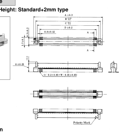
IReceptacle-Stacking Height: Standard+2mm type
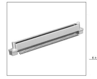
BPCB mounting pattern
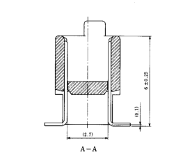
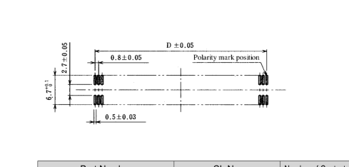
Unit: mm
| Part Number | CL No. | Number of Contacts | A | B | C | D |
|---|---|---|---|---|---|---|
| FX6A-020P-0.8SV2 | 576-0241-7 | 20 | 15.8 | 12.9 | 10.7 | 07.2 |
| FX6A-040P-0.8SV2 | 576-0243-2 | 40 | 23.8 | 20.9 | 18.7 | 15.2 |
| FX6A-050P-0.8SV2 | 576-0244-5 | 50 | 27.8 | 24.9 | 22.7 | 19.2 |
| FX6A-060P-0.8SV2 | 576-0245-8 | 60 | 31.8 | 28.9 | 26.7 | 23.2 |
| FX6A-080P-0.8SV2 | 576-0247-3 | 80 | 39.8 | 36.9 | 34.7 | 31.2 |
| FX6A-100P-0.8SV2 | 576-0248-6 | 100 | 47.8 | 44.9 | 42.7 | 39.2 |
Note:Determine a quantity of the stick package product for delivery, multiplying the insertion pieces per contact number by an integer. Please make sure that a quantity of the stick package product for delivery is determined per reel (1000 pieces). (Refer to the delivery form item on page A214 for details.)
A222
Page 11
Without Boss Type
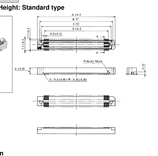
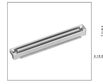
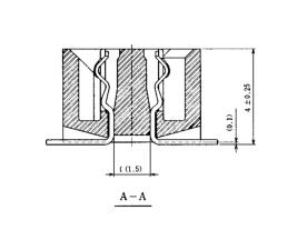
IReceptacle-Stacking Height: Standard type
BPCB mounting pattern
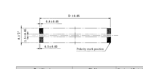
Unit: mm
| Part Number | CL No. | Number of Contacts | A | B | C | D |
|---|---|---|---|---|---|---|
| FX6A-020S-0.8SV | 576-0301-7 | 20 | 15.8 | 12.95 | 10.9 | 07.2 |
| FX6A-040S-0.8SV | 576-0303-2 | 40 | 23.8 | 20.95 | 18.9 | 15.2 |
| FX6A-050S-0.8SV | 576-0304-5 | 50 | 27.8 | 24.95 | 22.9 | 19.2 |
| FX6A-060S-0.8SV | 576-0305-8 | 60 | 31.8 | 28.95 | 26.9 | 23.2 |
| FX6A-080S-0.8SV | 576-0307-3 | 80 | 39.8 | 36.95 | 34.9 | 31.2 |
| FX6A-100S-0.8SV | 576-0308-6 | 100 | 47.8 | 44.95 | 42.9 | 39.2 |
Note:Determine a quantity of the stick package product for delivery, multiplying the insertion pieces per contact number by an integer. Please make sure that a quantity of the stick package product for delivery is determined per reel (1000 pieces). (Refer to the delivery form item on page A214 for details.)
A223
Page 12
Without Boss Type
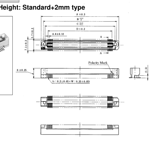
IReceptacle-Stacking Height: Standard+2mm type
BPCB mounting pattern
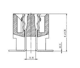
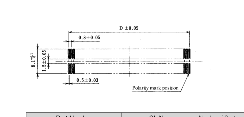
Unit: mm
| Part Number | CL No. | Number of Contacts | A | B | C | D |
|---|---|---|---|---|---|---|
| FX6A-020S-0.8SV2 | 576-0321-4 | 20 | 15.8 | 12.95 | 10.9 | 07.2 |
| FX6A-040S-0.8SV2 | 576-0323-0 | 40 | 23.8 | 20.95 | 18.9 | 15.2 |
| FX6A-050S-0.8SV2 | 576-0324-2 | 50 | 27.8 | 24.95 | 22.9 | 19.2 |
| FX6A-060S-0.8SV2 | 576-0325-5 | 60 | 31.8 | 28.95 | 26.9 | 23.2 |
| FX6A-080S-0.8SV2 | 576-0327-0 | 80 | 39.8 | 36.95 | 34.9 | 31.2 |
| FX6A-100S-0.8SV2 | 576-0328-3 | 100 | 47.8 | 44.95 | 42.9 | 39.2 |
Note:Determine a quantity of the stick package product for delivery, multiplying the insertion pieces per contact number by an integer. Please make sure that a quantity of the stick package product for delivery is determined per reel (1000 pieces). (Refer to the delivery form item on page A214 for details.)
A224
Page 13
BPrecautions 1. Tolerance Clearance on Mating Side
The effective contact length of the product is set to 1.7mm. Please use the products as to set the clearance within 1.0mm between the header and the receptacle in the mating process.
2. Mounting Temperature Profile (Reference)
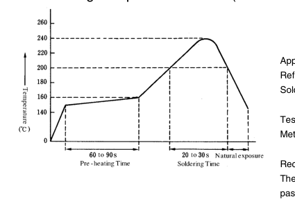
Applicable Conditions Reflow system Solder
Test board Metal mask thickness
:IR reflow :Paste type 63 Sn/37 Pb (Flux content 11 wt%) :Glass epoxy 110mm x 55mm x 1.6 mm :0.15 mm
Recommended temperature profile. The temperature may be slightly changed according to the solder paste type and amount.
3. Board to Board Size
The board to board size of the male/female connector shown in the application pattern doesn't include the solder paste thickness. Thus, after the connector is mounted on the board, consider that the board to board size will be widened in proportion to the solder paste thickness.
A225