

 Download PDF
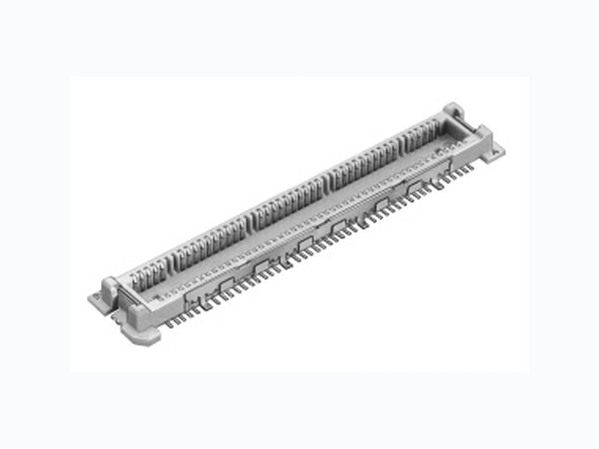
CL573-0002-7 HIROSE
Document overview
- PDF pages: 8
Technical content
Page 1
NEW NEW

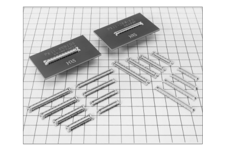
IFeatures
1. Low Profile Design
The board to board mating height of 2 mm suits smaller,thinner case designs.
2. Improved Transmission Efficiency Between
Boards
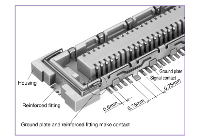
Transmission characteristics have been improved through a design that fixes ground plates to both sides of the header and receptacle.
3. 10 Signal:1 Ground Arrangement
Signal and ground are arranged in a ratio of 10:1 with the ground plate SMT connected to the board. The ground stability achieved serves to reduce noise.
4. Reinforced Fittings for Added Solder Weld
Strength
Reinforced fittings provide greater adhesion to the board,protecting against peeling.The unique connector design provides a connection between the fitting and the ground plate for a stronger ground.
5. Suited to High-Density Applications
The signal contact pitch of 0.5mm produces a smaller connector utilizing less board area for mounting.
6. Structure Prevents Solder Wicking
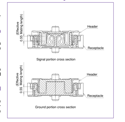
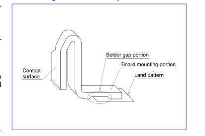
A solder gap has been designed into the contact SMT portion to prevent solder wicking.
7. Optional Ground Plate
An alternate style without the ground plate is available.The space provided by the ground plate removal has been filled with additional signal contacts.
Note: The thickness of the solder paste is not included in the 2 mm board-to-board stack height.
IApplications
Notebook computers, PDA, and other miniature electronic equipment.
GCross-Section of Mating
Detailed Figure of Solder Gap
2003.7
Page 2
IProduct Specifications
Storage temperature range
Rated current 0.3 A (Note 1) Operating temperature range
-55 to 85ç
-10 to +60ç (Note 2)
Storage humidity range
Rating Rated voltage 50 V AC
Operating humidity range
Relative humidity 95% or less
-40 to -70% (Note 2)
(No condensation)
| Item | Requirements | Conditions |
|---|---|---|
| 1. Insulation resistance | 100 Mø or greater | Measured at 100 V DC |
| 2. Voltage proof | No flashover or breakdown | 150 V AC applied for one minute |
| 3. Contact resistance | 60 mø or less | Measured at 100 mA |
| 4. Vibration | No electrical discontinuity for 1µs or greater No damage, cracks, or parts looseness | Frequency: 10 to 55 Hz, amplitude of 0.75 mm in 3 directions, 10 cycles each |
| 5. Shock | No electrical discontinuity for 1µs or longer No damage, cracks, or parts looseness | Acceleration of 490 m/s2, 11ms duration, sine half-wave waveform,for 3 cycles in the both directions of each of the 3 axes |
| 6. Damp heat (Steady state) | Contact resistance of 70 mø or less, insulation resistance of 100 Mø or greater, no damage, cracks, or parts looseness | Temperature of 40ç, humidity of 90 to 95%, duration 96 h |
| 7. Rapid change of temperature | Contact resistance of 70 mø or less, insulation resistance of 100 Mø or greater, no damage, cracks, or parts looseness | Temperature: -55ç ¡ 15 to 35ç ¡ 85ç ¡ 15 to 35ç Time: 30 min. ¡ 2 to 3 min. ¡ 30 min. ¡ 2 to 3 min. for 5 cycles |
| 8. Insertion/ Withdrawal life | Contact resistance of 70 mø or less No damage, cracks, or parts looseness | 50 times |
| 9. Resistance to soldering heat | No melting of resin portion which affects performance | Reflow: At the recommended temperature profile Soldering iron temperature: 300ç for 3 seconds |
Note 1: Please contact us when connector application exceeds 0.3 A rated current. Note 2: The term storage refers to an unused products prior to board mounting (including packing materials) that is being kept for a long period. The operating temperature and humidity range are applied to the non-conducting condition following board assembly. Note 3: The aforementioned specifications are representative of this series. For information on specific parts, confirm with Sales Office.
IMaterials
| Part | Material | Process | UL Rating | |
|---|---|---|---|---|
| Insulator | LCP resin | Beige | UL94V-0 | |
| Contacts | Copper alloy | Header | Engagement Area: Gold plating of 0.1µm Termination Area: Flash plating | ---------- |
| Phosphor bronze | Receptacle | |||
| Ground plate | Phosphor bronze | Solder plating | ---------- | |
| Reinforced fitting | Phosphor bronze | Tin plating | ---------- ---------- | |
| Reinforced plate | ||||
Note : The black dots on the insulater will not affect performance.
IProduct Number Configuration
Please use this information to discern the product specifications from the product number codes. To order, please select from the product number codes listed in tables on pages 3 to 6 of this catalog.
Type With Ground Plate FX 11L # - ✽ P - /✽ - SV (✽ ✽)
1 2 3
5
6 7
4
Type Without Ground Plate FX 11L # - ✽ P - SV (✽ ✽)
1 2 3 4 5 6 7
| 1 Series name : FX | 5 Connector type P : Header S : Receptacle |
| 2 Series No. : 11L | |
| 3 Form Symbol A : With guide post B : Without guide post | |
| 6 Contact form SV : Straight SMT | |
| 4 Number of contactsType with ground plate Signal/Ground:60/6, 80/8, 100/10, 120/12 Type without ground Signal: 68, 92, 116, 140 | |
| 7 Blank: Tray packaging (Without pick-and-place tape) (21): Embossed tape packaging (Without pick-and-place tape) (22): Embossed tape packaging (With pick-and-place tape) |
Page 3
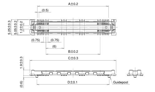
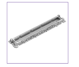
IHeaders with Ground Plate
| HRS No. | Number of C Product No. Signal G | ontacts A B round | C | D | E | Notes |
| CL573-0002-7-✽ ✽ | FX11LA-060P/06-SV (✽ ✽) 060 | 06 17.5 12 | 22.6 | 18 | 19.4 | With guideposts |
| CL573-0003-0-✽ ✽ | FX11LA-080P/08-SV (✽ ✽) 080 | 08 23.5 18 | 28.6 | 24 | 25.4 | |
| CL573-0004-2-✽ ✽ | FX11LA-100P/10-SV (✽ ✽) 100 | 10 29.5 24 | 34.6 | 30 | 31.4 | |
| CL573-0005-5-✽ ✽ | FX11LA-120P/12-SV (✽ ✽) 120 | 12 35.5 30 | 40.6 | 36 | 37.4 | |
| CL573-0012-0-✽ ✽ | FX11LB-060P/06-SV (✽ ✽) 060 | 06 17.5 12 | 22.6 | ---------- | 19.4 | Without guideposts |
| CL573-0013-3-✽ ✽ | FX11LB-080P/08-SV (✽ ✽) 080 | 08 23.5 18 | 28.6 | ---------- | 25.4 | |
| CL573-0014-6-✽ ✽ | FX11LB-100P/10-SV (✽ ✽) 100 | 10 29.5 24 | 34.6 | ---------- | 31.4 | |
| CL573-0015-9-✽ ✽ | FX11LB-120P/12-SV (✽ ✽) 120 | 12 35.5 30 | 40.6 | ----------- | 37.4 |

Note 1: There is no polarity in terms of board mounting for this product. Note 2: The coplanarity of this product's SMT leads is 0.1 mm or less. Note 3: Please order embossed tape packaged items by the reel. (One reel holds 1,000 pieces.)
BRecommended Land Pattern Dimensions (Metal Mask Dimensions)
Recommended metal mask thickness: 0.15 mm
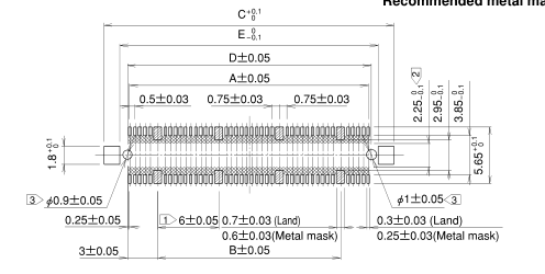
Note Cross-hatched portions, totaling n places, indicate the ground circuits. The cross-hatched area inside the SMT land may come into contact with the connector contacts and thus care should be taken that the pattern does not extend beyond the SMT land width.
Page 4
IReceptacles with Ground Plate
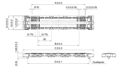
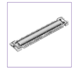
| HRS No. | Number of Contacts Product No. Signal Ground | A B C D E | F Notes |
| CL573-0102-1-✽ ✽ | FX11LA-060S/06-SV (✽ ✽) 060 06 1 | 7.5 12 25 20.8 25.4 2 | 2.2 8.2 With guideposts 4.2 0.2 |
| CL573-0103-4-✽ ✽ | FX11LA-080S/08-SV (✽ ✽) 080 08 2 | 3.5 18 31 26.8 31.4 2 | |
| CL573-0104-7-✽ ✽ | FX11LA-100S/10-SV (✽ ✽) 100 10 2 | 9.5 24 37 32.8 37.4 3 | |
| CL573-0105-7-✽ ✽ | FX11LA-120S/12-SV (✽ ✽) 120 12 3 | 5.5 30 43 38.8 43.4 4 | |
| CL573-0112-5-✽ ✽ | FX11LB-060S/06-SV (✽ ✽) 060 06 1 | 7.5 12 25 ---------- 25.4 2 | 2.2 8.2 Without guideposts 4.2 0.2 |
| CL573-0113-8-✽ ✽ | FX11LB-080S/08-SV (✽ ✽) 080 08 2 | 3.5 18 31 ---------- 31.4 2 | |
| CL573-0114-0-✽ ✽ | FX11LB-100S/10-SV (✽ ✽) 100 10 2 | 9.5 24 37 ---------- 37.4 3 | |
| CL573-0105-3-✽ ✽ | FX11LB-120S/12-SV (✽ ✽)s 120 12 3 | 5.5 30 43 ---------- 43.4 4 |

Note 1: There is no polarity in terms of board mounting for this product. Note 2: The coplanarity of this product's SMT leads is 0.1mm or less. Note 3: Please order embossed tape packaged items by the reel. (One reel holds 1,000 pieces.)
BRecommended Land Pattern Dimensions (Metal Mask Dimensions)
Recommended metal mask thickness: 0.15 mm
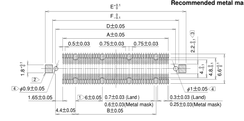
Note Cross-hatched portions, totaling n places, indicate the ground circuits. Cross-hatched portions, totaling 2 places, indicate the reinforced fittings. The cross-hatched area inside the SMT land may come into contact with the connector contacts and thus care should be taken that the pattern does not extend beyond the SMT land width.
Page 5
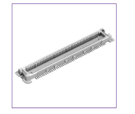
IHeaders without Ground Plate
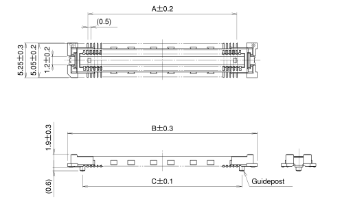
| HRS No. | Product No. | Number of Contacts | A | B | C D | Notes |
| Signal | ||||||
| CL573-0042-1-✽ ✽ | FX11LA-068P-SV (✽ ✽) | 068 | 16.5 | 22.6 | 18 19.4 | With guideposts |
| CL573-0043-4-✽ ✽ | FX11LA-092P-SV (✽ ✽) | 092 | 22.5 | 28.6 | 24 25.4 | |
| CL573-0044-7-✽ ✽ | FX11LA-116P-SV (✽ ✽) | 116 | 28.5 | 34.6 | 30 31.4 | |
| CL573-0045-0-✽ ✽ | FX11LA-140P-SV (✽ ✽) | 140 | 34.5 | 40.6 | 36 37.4 | |
| CL573-0052-5-✽ ✽ | FX11LB-068P-SV (✽ ✽) | 068 | 16.5 | 22.6 | ---------- 19.4 | Without guideposts |
| CL573-0053-8-✽ ✽ | FX11LB-092P-SV (✽ ✽) | 092 | 22.5 | 28.6 | ---------- 25.4 | |
| CL573-0054-0-✽ ✽ | FX11LB-116P-SV (✽ ✽) | 116 | 28.5 | 34.6 | ---------- 31.4 | |
| CL573-0055-3-✽ ✽ | FX11LB-140P-SV (✽ ✽) | 140 | 34.5 | 40.6 | ---------- 37.4 |

Note 1: There is no polarity in terms of board mounting for this product. Note 2: The coplanarity of this product's SMT leads is 0.1 mm or less. Note 3: Please order embossed tape packaged items by the reel. (One reel holds 1,000 pieces.)
BRecommended Land Pattern Dimensions (Metal Mask Dimensions)
Recommended metal mask thickness: 0.15 mm
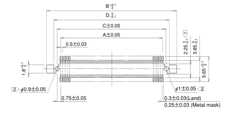
Note The cross-hatched area inside the SMT land may come into contact with the connector contacts and thus care should be taken that the pattern does not extend beyond the SMT land width.
Page 6
IReceptacles without Ground Plate
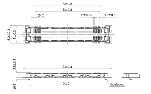
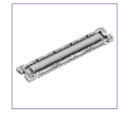
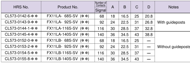

Note 1: There is no polarity in terms of board mounting for this product. Note 2: The coplanarity of this product's SMT leads is 0.1 mm or less. Note 3: Please order embossed tape packaged items by the reel. (One reel holds 1,000 pieces.)
BRecommended Land Pattern Dimensions (Metal Mask Dimensions)
Recommended metal mask thickness: 0.15 mm
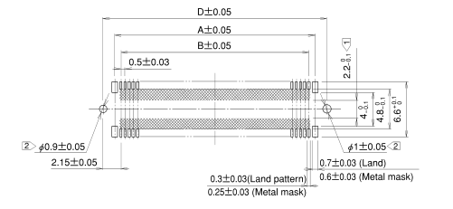
Note The cross-hatched area inside the SMT land may come into contact with the connector contacts and thus care should be taken that the pattern does not extend beyond the SMT land width.
Page 7
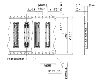
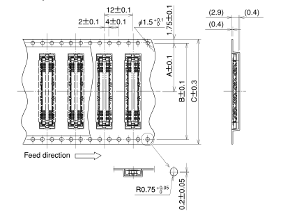
BEmbossed Carrier Tape Dimensions
GHeaders
GReceptacles
GReel Packaging Dimensions
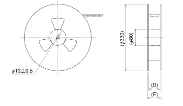
Insertion Connector
A B C D E
FX11L#-060P/06-SV
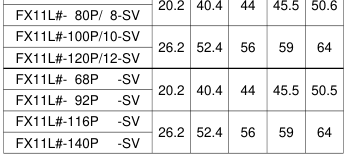
Note 1: There is no polarity in terms of embossed tape packaging for this product. Note 2: Left figure is representative of products with ground plates.
Insertion Connector
A B C D E
FX11L#-060S/06-SV
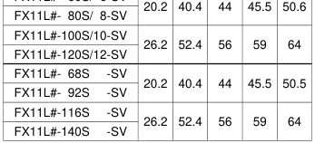
Note 1: There is no polarity in terms of embossed tape packaging for this product. Note 2: Left figure is representative of products with ground plates.
Page 8
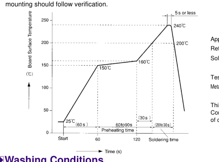
BRecommended Temperature Profile
This temperature profile is a reference for the setting conditions described below. It will differ depending on conditions and so
BWashing Conditions
Organic Solvent Washing
| Solvent | Room temperature washing | Heated washing |
| IPA (Isopropyl alcohol) | Yes | Yes |
| HCFC (Hydrochlorofluorocarbon) | Yes | Yes |
Water Type Washing
Applicable Conditions Reflow method : IR reflow Solder
: Cream type 63Sn/37Pb (Flux component of 9wt%)
Test substrate : Glass epoxy 85 x 110 x 1.6mm Metal mask thickness : 0.15mm
This temperature profile is a recommendation. Conditions may change somewhat depending on the type of cream solder and the amount.
When using water type cleaning agents (e.g., terpene, and alkali saponifiers), select the cleaning agent based on the documentation issued by the various manufacturers of cleaning agents which describes the effects on metals and resins. Be careful that parts are not left with moisture remaining on them.
Washing Precautions
Residual flux or cleaning agent on the contacts when washing with organic solvents or water type cleaners can give rise to the deterioration of electrical performance. In this regard it is important to check whether a thorough washing has been performed.
BConnector Handling Precautions
1. Allowable Creepage Dimensions at Time of Mating
The effective coupling length of this product is 0.55 mm for the signal portion and the ground portion. The creepage of the header and receptacle at the time of mating should be within 0.18 mm of the completely coupled condition.
2. Retension of Boards
Avoid the support of boards by connectors alone and adopt a board locking measure that does not rely on the connectors.
3. Solder Repair
Flux may rise as far as the contact portion of the connector depending on the flux coating and other factors at the time of repair. This will cause poor contact reliability; therefore, before use, the aforementioned washing conditions should be taken into consideration prior to connector washing.
4. Miscellaneous
- Note that excessive twisting while inserting or withdrawing connectors will cause damage.
- The shade of the molded items may vary somewhat depending on the manufacturing lot; however, this does not affect performance.


The contents of this catalog are current as of date of publication. Contents are subject to change without notice for the purpose of improvements.