


 Download PDF
FSCQ0765RT FAIRCHILD
Document overview
- PDF pages: 24
Technical content
Page 1
www.fairchildsemi.com

Features
- Optimized for Quasi-Resonant Converter (QRC)
- Advanced Burst-Mode operation for under 1 W standby power consumption
- Pulse by Pulse Current Limit (5A)
- Over load protection (OLP) - Auto restart
- Over voltage protection (OVP) - Auto restart
- Abnormal Over Current Protection (AOCP) - Latch
- Internal Thermal Shutdown (TSD) - Latch
- Under Voltage Lock Out (UVLO) with hysteresis
- Low Startup Current (typical : 25uA)
- Low Operating Current (typical : 4mA)
- Internal High Voltage SenseFET
- Built-in Soft Start (20ms)
- Extended Quasi-resonant Switching for Wide Load Range
Application
- CTV
- DVD Receiver
- Audio Power Supply
Description
In general, Quasi-Resonant Converter (QRC) shows lower EMI and higher power conversion efficiency compared to the conventional hard switched converter with a fixed switching frequency. Therefore, it is well suited for applications that are sensitive to the noise, such as color TV and audio. The FSCQ0765RT is an integrated Pulse Width Modulation (PWM) controller and Sense FET specifically designed for Quasi-resonant off-line Switch Mode Power Supplies (SMPS) with minimal external components. The PWM controller includes integrated fixed frequency oscillator, under voltage lockout, leading edge blanking (LEB), optimized gate driver, internal soft start, temperature compensated precise
current sources for a loop compensation and self protection circuitry. Compared with discrete MOSFET and PWM controller solution, it can reduce total cost, component count, size and weight simultaneously increasing efficiency, productivity, and system reliability. This device is a basic platform well suited for cost effective designs of Quasi resonant switching flyback converters.
©2004 Fairchild Semiconductor Corporation
| OUTPUT POWER TABLE | ||
| PRODUC | 230VAC ±15%(2) T Open Frame(1) | 85-265VAC |
| Open Frame(1) | ||
| FSCQ0765 | RT 100 W | 85 W |
| FSCQ1265 | RT 170 W | 140 W |
| FSCQ1565 | RT 210 W | 170 W |
Table 1. Notes: 1. Maximum practical continuous power in an open frame design at 50°C ambient. 2. 230 VAC or 100/115 VAC with doubler.
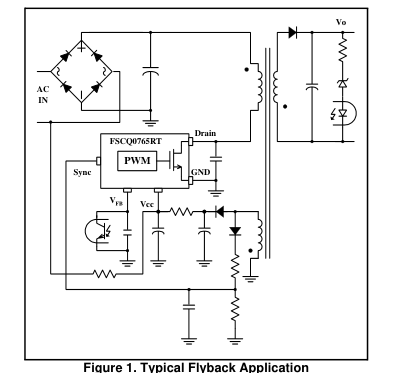
Typical Circuit
Rev.1.0.1
Page 2
Internal Block Diagram
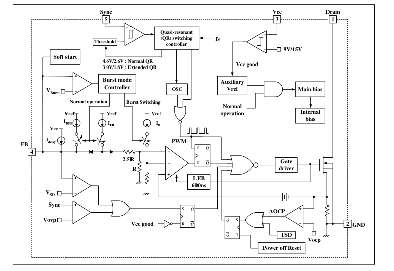
Figure 2. Functional Block Diagram of FSCQ0765RT
Page 3
Pin Definitions
| Pin Number | Pin Name | Pin Function Description |
|---|---|---|
| 1 | Drain | High voltage power SenseFET drain connection. |
| 2 | GND | This pin is the control ground and the SenseFET source. |
| 3 | Vcc | This pin is the positive supply input. This pin provides internal operating current for both start-up and steady-state operation. |
| 4 | Vfb | This pin is internally connected to the inverting input of the PWM comparator. The collector of an opto-coupler is typically tied to this pin. For stable operation, a capacitor should be placed between this pin and GND. If the voltage of this pin reaches 7.5V, the over load protection triggers resulting in shutdown of the FPS. |
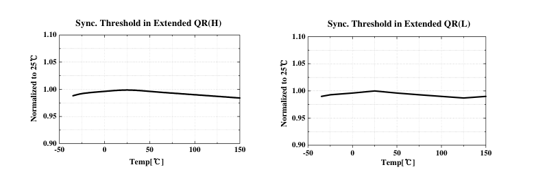
| 5 | Sync | This pin is internally connected to the sync detect comparator for quasi resonant switching. In normal quasi-resonant operation, the threshold of the sync comparator is 4.6V/2.6V. Meanwhile, the sync threshold is changed to 3.0V/1.8V in extended quasi-resonant operation. |
Pin Configuration
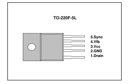
Figure 3. Pin Configuration (Top View)
Page 4
Absolute Maximum Ratings
(Ta=25°C, unless otherwise specified)
| Parameter | Symbol | Value | Unit |
|---|---|---|---|
| Drain-Source (GND) Voltage (1) | VDSS | 650 | V |
| Drain-Gate Voltage (RGS=1MΩ) | VDGR | 650 | V |
| Gate-Source (GND) Voltage | VGS | ±30 | V |
| Drain Current Pulsed (2) | IDM | 15 | ADC |
| Single Pulsed Avalanche Energy (3) | EAS | 570 | mJ |
| Continuous Drain Current (Tc = 25°C) | ID | 3.8 | ADC |
| Continuous Drain Current (TC=100°C) | ID | 2.4 | ADC |
| Supply Voltage | VCC | 20 | V |
| Analog Input Voltage Range | Vsync | -0.3 to 13V | V |
| VFB | -0.3 to VCC | V | |
| Total Power Dissipation | PD | 45 | W |
| Operating Junction Temperature | TJ | +150 | °C |
| Operating Ambient Temperature | TA | -25 to +85 | °C |
| Storage Temperature Range | TSTG | -55 to +150 | °C |
| Thermal Resistance | Rthjc | 2.6 | °C/W |
Notes: 1. Tj = 25°C to 150°C 2. Repetitive rating: Pulse width limited by maximum junction temperature 3. L = 21mH, VDD = 50V, RG = 25Ω, starting Tj = 25°C
Page 5
Electrical Characteristics (SenseFET Part)
(Ta=25°C unless otherwise specified)
| Parameter | Symbol | Condition | Min. | Typ. | Max. | Unit |
|---|---|---|---|---|---|---|
| Drain-Source Breakdown Voltage | BVDSS | VGS = 0V, ID = 250µA | 650 | - | - | V |
| Zero Gate Voltage Drain Current | IDSS | VDS = Max, Rating, VGS = 0V | - | - | 200 | µA |
| VDS= 0.8*Max., Rating VGS = 0V, TC = 85°C | - | - | 300 | µA | ||
| Static Drain-source on Resistance (Note) | RDS(ON) | VGS = 10V, ID = 2.3A | - | 1.4 | 1.6 | Ω |
| Input Capacitance | Ciss | VGS = 0V, VDS = 25V, f = 1MHz | - | 1415 | 1840 | pF |
| Output Capacitance | Coss | - | 100 | 130 | ||
| Reverse Transfer Capacitance | Crss | - | 15 | 20 | ||
| Turn on Delay Time | td(on) | VDD= 0.5BVDSS, ID= 7.0A (MOSFET switching times are essentially independent of operating temperature) | - | 25 | 60 | ns |
| Rise Time | tr | - | 60 | 130 | ||
| Turn Off Delay Time | td (off) | - | 110 | 230 | ||
| Fall Time | tf | - | 65 | 140 | ||
| Total Gate Charge (Gate-Source+Gate-Drain) | Qg | VGS = 10V, ID = 7.0A, VDS = 0.5BVDSS (MOSFET Switching times are essentially independent of operating temperature) | - | 40 | 52 | nC |
| Gate-Source Charge | Qgs | - | 7 | 9.1 | ||
| Gate-Drain (Miller) Charge | Qgd | - | 12 | 17 |
Note: 1. Pulse test : Pulse width ≤ 300µS, duty ≤ 2%
Page 6
Electrical Characteristics (Continued)
(Ta=25°C unless otherwise specified)
| Parameter | Symbol | Condition | Min. | Typ. | Max. | Unit |
|---|---|---|---|---|---|---|
| UVLO SECTION | ||||||
| Vcc Start Threshold Voltage | VSTART | VFB = GND | 14 | 15 | 16 | V |
| Vcc Stop Threshold Voltage | VSTOP | VFB = GND | 8 | 9 | 10 | V |
| SENSEFET SECTION | ||||||
| Drain To PKG Breakdown Voltage (Note4) | BVpkg | 60HZ AC, Ta = 25°C | 3500 | - | - | V |
| Drain To Source Breakdown Voltage | BVdss | Ta = 25°C | 650 | - | - | V |
| Drain To Source Leakage Current | Idss | Vdrain = 400V, Ta = 25°C | - | - | 200 | uA |
| OSCILLATOR SECTION | ||||||
| Initial Frequency | FOSC | - | 18 | 20 | 22 | kHz |
| Voltage Stability | FSTABLE | 12V ≤ Vcc ≤ 23V | 0 | 1 | 3 | % |
| Temperature Stability (Note2) | ∆FOSC | -25°C ≤ Ta ≤ 85°C | 0 | ±5 | ±10 | % |
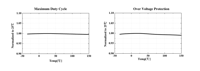
| Maximum Duty Cycle | DMAX | - | 92 | 95 | 98 | % |
| Minimum Duty Cycle | DMIN | - | - | - | 0 | % |
| FEEDBACK SECTION | ||||||
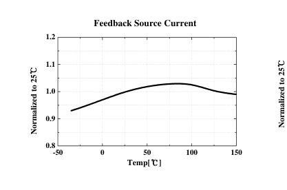
| Feedback Source Current | IFB | VFB = 0.8V | 0.5 | 0.65 | 0.8 | mA |
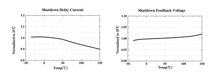
| Shutdown Feedback Voltage | VSD | Vfb ≥ 6.9V | 7.0 | 7.5 | 8.0 | V |
| Shutdown Delay Current | IDELAY | VFB = 5V | 4 | 5 | 6 | µA |
| PROTECTION SECTION | ||||||
| Over Voltage Protection | VOVP | Vsync ≥ 11V | 11 | 12 | 13 | V |
| Over Current Latch Voltage (Note2) | VOCL | - | 0.9 | 1.0 | 1.1 | V |
| Thermal Shutdown Temp (Note4) | TSD | - | 140 | - | °C | |
Note: 1. These parameters is the current flowing in the Control IC. 2. These parameters, although guaranteed, are tested only in EDS (wafer test) process. 3. These parameters indicate Inductor Current. 4. These parameters, although guaranteed at the design, are not tested in mass production.
Page 7
Electrical Characteristics (Continued)
(Ta=25°C unless otherwise specified)
| Parameter | Symbol | Condition | Min. | Typ. | Max. | Unit |
|---|---|---|---|---|---|---|
| Sync SECTION | ||||||
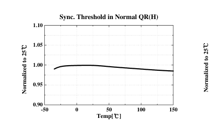
| Sync Threshold in normal QR (H) | VSH1 | Vcc = 16V, Vfb = 5V | 4.2 | 4.6 | 5.0 | V |
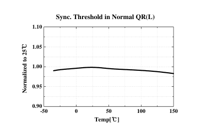
| Sync Threshold in normal QR (L) | VSL1 | Vcc = 16V, Vfb = 5V | 2.3 | 2.6 | 2.9 | V |
| Sync Threshold in extended QR (H) | VSH2 | Vcc = 16V, Vfb = 5V | 2.7 | 3.0 | 3.3 | V |
| Sync Threshold in extended QR (L) | VSL2 | Vcc = 16V, Vfb = 5V | 1.6 | 1.8 | 2.0 | V |
| Extended QR enable frequency | FSYH | - | 90 | - | kHz | |
| Extended QR disable frequency | FSYL | - | 45 | - | kHz | |
| BURST MODE SECTION | ||||||
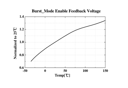
| Burst Mode Enable Feedback Voltage | VBEN | 0.25 | 0.40 | 0.55 | V | |
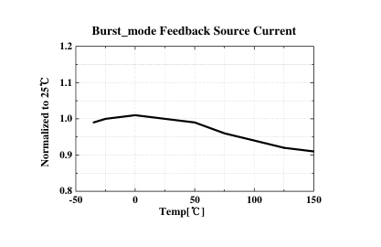
| Burst Mode Feedback Source Current | IBFB | 60 | 100 | 140 | uA | |
| Burst Mode switching Time | TBS | VFB = 0V | 1.2 | 1.4 | 1.6 | ms |
| Burst Mode Hold Time | TBH | VFB = 0V | 1.2 | 1.4 | 1.6 | ms |
| SOFTSTART SECTION | ||||||
| Soft start Time (Note2) | TSS | 18 | 20 | 22 | ms | |
| CURRENT LIMIT(SELF-PROTECTION)SECTION | ||||||
| Peak Current Limit (Note3) | ILIM | - | 4.4 | 5.0 | 5.6 | A |
| Burst Mode Peak Current Limit (Note4) | IBPK | - | 0.65 | 0.9 | 1.15 | A |
| TOTAL DEVICE SECTION | ||||||
| Startup Current | ISTART | VCC = VSTART-0.1V | - | 25 | 50 | uA |
| Sustain Latch Current | ISL | VCC = VSTOP-0.1V | - | 50 | 100 | uA |
| Operating Supply Current (Note1) - In normal operation - In burst mode (without switching) | ||||||
| IOP | Vfb = 2V, VCC = 18V | - | 4 | 6 | mA | |
| IOB | Vfb = GND, VCC = 18V | - | 0.25 | 0.50 | mA | |
Note: 1. These parameters is the current flowing in the Control IC. 2. These parameters, although guaranteed, are tested only in EDS (wafer test) process. 3. These parameters indicate Inductor Current. 4. These parameters, although guaranteed at the design, are not tested in mass production.
Page 8
Comparison Between KA5Q0765RT and FSCQ0765RT
| Function | KA5Q0765RT | FSCQ0765RT | FSCQ0765RT Advantages |
| Startup Current | Max. 200uA | Max. 50uA | Lower standby power consumption |
| Operating supply Current | Typ. 10mA | Typ. 4mA | Operating current is reduced in burst operation to minimize standby power consumption - Normal operation : 4mA - Burst mode with switching : 4mA - Burst mode without switching : 0.25mA |
| Switching in Burst mode | Quasi-resonant switching | Fixed frequency switching (20kHz) | |
| Output regulation in standby mode | Vcc control with hysteresis | Output voltage feedback control | Easy to determine the output voltage in the standby mode |
| Output Voltage drop in burst mode | about half | Any level | Lower power consumption in the standby mode through larger output voltage drop |
| Primary side regulation | Available | N/A | |
| Soft start | N/A | Available | Internal soft-start (20ms) |
| Extended Quasi-resonant switching | N/A | Available | - Guarantees wide load range - Improved efficiency at high line input |
Page 9
Electrical characteristics
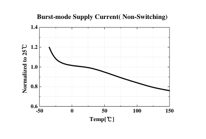
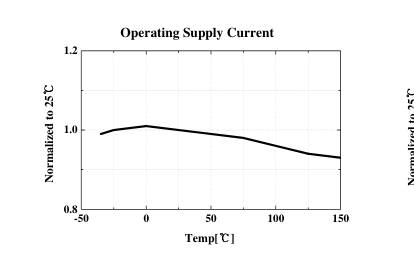
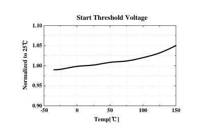
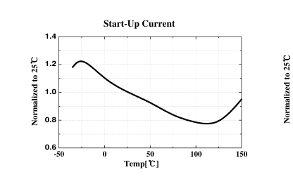
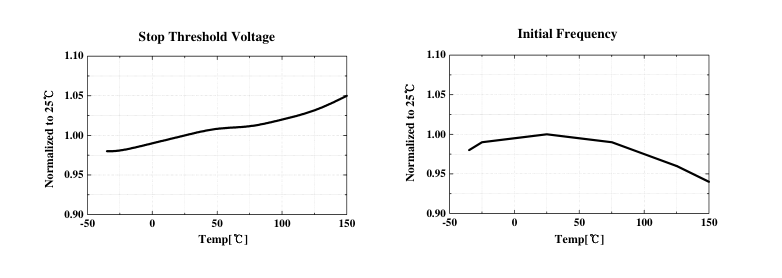
Page 10
Electrical characteristics
Page 11
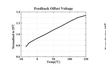
Electrical characteristics
Page 12
Functional Description
- Startup : Figure 4 shows the typical startup circuit and 1. 1. 1. transformer auxiliary winding for FSCQ0765RT application. Before FSCQ0765RT begins switching, FSCQ0765RT consumes only startup current (typically 25uA) and the current supplied from the AC line charges the external capacitor (Ca1) that is connected to the Vcc pin. When Vcc reaches start voltage of 15V (VSTART), FSCQ0765RT begins switching, and the current consumed by FSCQ0765RT increases to 4mA. Then, FSCQ0765RT continues its normal switching operation and the power required for this device is supplied from the transformer auxiliary winding, unless Vcc drops below the stop voltage of 9V (VSTOP). To guarantee the
stable operation of the control IC, Vcc has under voltage lockout (UVLO) with 6V hysteresis. Figure 5 shows the relation between the FSCQ0765RT operating supply current and the supply voltage (Vcc).
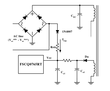
Figure 4. Startup circuit
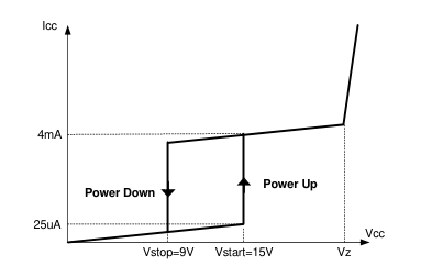
Figure 5. Relation between operating supply current and
Vcc voltage
The minimum average of the current supplied from the AC is given by
min Vstart 2 Vac
⋅
1
avg Isup = ------------------------------ – -------------- ⋅
---------- Rstr 2 π
where Vacmin is the minimum input voltage, Vstart is the FSCQ0765RT start voltage (15V) and Rstr is the startup resistor. The startup resistor should be chosen so that Isupavg is larger than the maximum startup current (50uA). Once the resistor value is determined, the maximum loss in the startup resistor is obtained as
2
max
max
2 Vstart 2 2 Vstart Vac Vac (
) +
⋅ ⋅
1 Loss =
--------------------------------------------------- – ------------------------------------------------------ ---------- ⋅ Rstr
2
π
where Vacmax is the maximum input voltage. The startup resistor should have proper rated dissipation wattage.
- Synchronization : FSCQ0765RT employs quasi-resonant switching technique to minimize the switching noise and loss. In this technique, a capacitor (Cr) is added between the MOSFET drain and source as shown in Figure 6. The basic waveforms of quasi-resonant converter are shown in Figure 7. The external capacitor lowers the rising slop of drain voltage to reduce the EMI caused when the MOSFET turns off. In order to minimize the MOSFET switching loss, the MOSFET should be turned on when the drain voltage reaches its minimum value as shown in Figure 7.
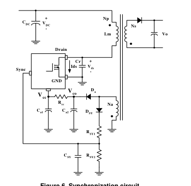
Figure 6. Synchronization circuit
Page 13
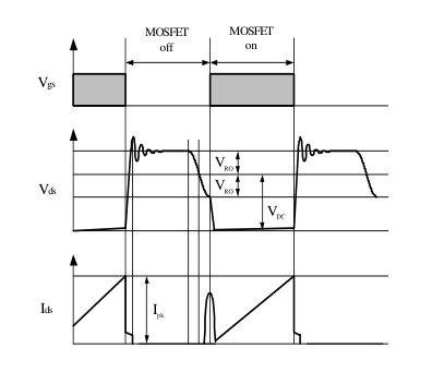
Figure 7. Quasi-resonant operation waveforms
The minimum drain voltage is indirectly detected by monitoring the Vcc winding voltage as shown in Figure 6 and 8. The voltage divider RSY1 and RSY2 should be chosen so that the peak voltage of sync signal (Vsypk) is lower than the OVP voltage (12V) in order to avoid triggering OVP in normal operation. It is typical to set Vsypk to be lower than OVP voltage by 3-4 V. In order to detect the optimum time to turn on MOSFET, the sync capacitor (CSY) should be determined so that TR is the same with TQ as shown in Figure 8. The TR and TQ are given as, respectively
Vco RSY2
⋅ ⋅ln --------- ⋅ TR RSY2 CSY
-----------------------------------
=
2.6 RSY1 RSY2 +
Lm Ceo TQ = π ⋅ ⋅
Na Vo VFO ⋅ ( + )
Vco
VFa
= ----------------------------------------- – Ns
where Lm is the primary side inductance of the transformer, Ns and Na are the number of turns for the output winding and Vcc winding, respectively, VFo and VFa are the diode forward voltage drops of the output winding and Vcc winding, respectively, and Ceo is the sum of the output capacitance of MOSFET and external capacitor Cr.
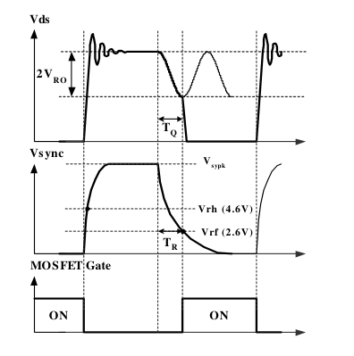
Figure 8. Normal quasi-resonant operation waveforms
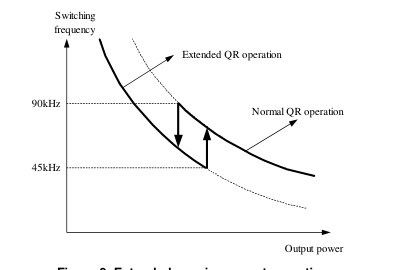
Figure 9. Extended quasi-resonant operation
In general, quasi-resonant converter has a limitation in a wide load range application, since the switching frequency increases as the output load decreases, resulting in a severe switching loss in the light load condition. In order to get over this limitation, FSCQ0765RT employs extended quasiresonant switching operation. Figure 9 shows the mode change between normal quasi-resonant operation and extended quasi-resonant operation. In the normal quasiresonant operation, the FSCQ0765RT enters into the extended quasi-resonant operation when the switching frequency exceeds 90kHz as the load reduces. Then, the MOSFET is turned on, when the drain voltage reaches the
Page 14
second minimum level as shown in Figure 10, which reduces the switching frequency. Once FSCQ0765RT enters into extended quasi-resonant operation, the first sync signal is ignored. After the first sync signal is applied, the sync threshold levels are changed from 4.6V and 2.6V to 3V and 1.8V, respectively, and the MOSFET turn-on time is synchronized to the second sync signal. The FSCQ0765RT goes back to its normal quasi-resonant operation when the switching frequency reaches 45kHz as the load increases.
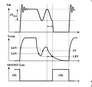
Figure 10. Extended quasi-resonant operation waveforms
- Feedback Control : FSCQ0765RT employs current mode control, as shown in Figure 11. An opto-coupler (such as the H11A817A) and shunt regulator (such as the KA431) are typically used to implement the feedback network. Comparing the feedback voltage with the voltage across the Rsense resistor plus an offset voltage makes it possible to control the switching duty cycle. When the reference pin voltage of the KA431 exceeds the internal reference voltage of 2.5V, the H11A817A LED current increases, thus pulling down the feedback voltage and reducing the duty cycle. This event typically happens when the input voltage is increased or the output load is decreased.
3.1 Pulse-by-pulse current limit: Because current mode control is employed, the peak current through the Sense FET is limited by the inverting input of PWM comparator (Vfb\*) as shown in Figure 11. The feedback current (IFB) and internal resistors are designed so that the maximum cathode voltage of diode D2 is about 2.8V, which occurs when all IFB flows through the internal resistors. Since D1 is blocked when the feedback voltage (Vfb) exceeds 2.8V, the maximum voltage of the cathode of D2 is clamped at this voltage, thus clamping Vfb\*. Therefore, the peak value of the current through the Sense FET is limited.
3.2 Leading edge blanking (LEB) : At the instant the internal Sense FET is turned on, there usually exists a high current spike through the Sense FET, caused by external resonant capacitor across the MOSFET and secondary-side rectifier reverse recovery. Excessive voltage across the Rsense resistor would lead to incorrect feedback operation in the current mode PWM control. To counter this effect, the FSCQ0765RT employs a leading edge blanking (LEB) circuit. This circuit inhibits the PWM comparator for a short time (TLEB) after the Sense FET is turned on.
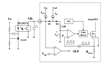
Figure 11. Pulse width modulation (PWM) circuit
- Protection Circuit : The FSCQ0765RT has several self protective functions such as over load protection (OLP), abnormal over current protection (AOCP), over voltage protection (OVP) and thermal shutdown (TSD). OLP and OVP are auto-restart mode protection, while TSD and AOCP are latch mode protection. Because these protection circuits are fully integrated into the IC without external components, the reliability can be improved without increasing cost. -Auto-restart mode protection: Once the fault condition is detected, switching is terminated and the Sense FET remains off. This causes Vcc to fall. When Vcc falls down to the under voltage lockout (UVLO) stop voltage of 9V, the
protection is reset and FSCQ0765RT consumes only startup current (25uA). Then, Vcc capacitor is charged up, since the current supplied through the startup resistor is larger than the current that FPS consumes. When Vcc reaches the start voltage of 15V, FSCQ0765RT resumes its normal operation. If the fault condition is not removed, the SenseFET remains off and Vcc drops to stop voltage again. In this manner, the auto-restart can alternately enable and disable the switching of the power Sense FET until the fault condition is eliminated (see Figure 12). -Latch mode protection: Once protection triggers, switching is terminated and the Sense FET remains off until
the AC power line is un-plugged. Then, Vcc continues charging and discharging between 9V and 15V. The latch is reset only when Vcc is discharged to 6V by un-plugging the Ac power line.
Page 15
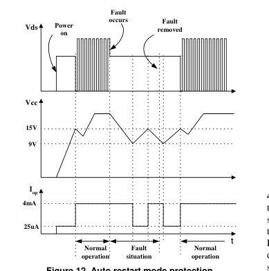
Figure 12. Auto restart mode protection
4.1 Over Load Protection (OLP) : Overload is defined as the load current exceeding its normal level due to an unexpected abnormal event. In this situation, the protection circuit should trigger in order to protect the SMPS. However, even when the SMPS is in the normal operation, the over load protection circuit can be triggered during the load transition. In order to avoid this undesired operation, the over load protection circuit is designed to trigger after a specified time to determine whether it is a transient situation or an overload situation. Because of the pulse-by-pulse current limit capability, the maximum peak current through the Sense FET is limited, and therefore the maximum input
power is restricted with a given input voltage. If the output consumes more than this maximum power, the output voltage (Vo) decreases below the set voltage. This reduces the current through the opto-coupler LED, which also reduces the opto-coupler transistor current, thus increasing the feedback voltage (Vfb). If Vfb exceeds 2.8V, D1 is blocked and the 5uA current source starts to charge CB slowly up to Vcc. In this condition, Vfb continues increasing until it reaches 7.5V, when the switching operation is terminated as shown in Figure 13. The delay time for shutdown is the time required to charge CB from 2.8V to 7.5V with 5uA. In general, a 20 ~ 50 ms delay time is typical
for most applications. This protection is implemented in auto restart mode.
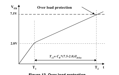
Figure 13. Over load protection
4.2 Abnormal Over Current Protection (AOCP) : When the secondary rectifier diodes or the transformer pins are shorted, a steep current with extremely high di/dt can flow through the SenseFET during the LEB time. Even though the FSCQ0765RT has OLP (Over Load Protection), it is not enough to protect the FSCQ0765RT in that abnormal case, since sever current stress will be imposed on the SenseFET until OLP triggers. The FSCQ0765RT has an internal AOCP (Abnormal Over Current Protection) circuit as shown in Figure 14. When the gate turn-on signal is applied to the power Sense FET, the AOCP block is enabled and monitors the current through the sensing resistor. The voltage across
the resistor is then compared with a preset AOCP level. If the sensing resistor voltage is greater than the AOCP level, the set signal is applied to the latch, resulting in the shutdown of SMPS. This protection is implemented in latch mode.
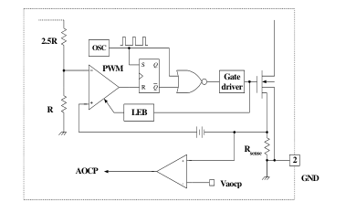
Figure 14. AOCP block
4.3 Over voltage Protection (OVP) : If the secondary side feedback circuit were to malfunction or a solder defect caused an open in the feedback path, the current through the opto-coupler transistor becomes almost zero. Then, Vfb climbs up in a similar manner to the over load situation,
Page 16
forcing the preset maximum current to be supplied to the SMPS until the over load protection triggers. Because more energy than required is provided to the output, the output voltage may exceed the rated voltage before the over load protection triggers, resulting in the breakdown of the devices in the secondary side. In order to prevent this situation, an over voltage protection (OVP) circuit is employed. In general, the peak voltage of the sync signal is proportional to the output voltage and the FSCQ0765RT uses sync signal instead of directly monitoring the output voltage. If sync signal exceeds 12V, an OVP is triggered resulting in a shutdown of SMPS. In order to avoid undesired triggering of
OVP during normal operation, the peak voltage of sync signal should be designed to be below 12V. This protection is implemented in auto restart mode.
4.4 Thermal Shutdown (TSD) : The SenseFET and the control IC are built in one package. This makes it easy for the control IC to detect the abnormal over temperature of the SenseFET. When the temperature exceeds approximately 150°C, the thermal shutdown triggers. This protection is implemented in latch mode.
- Soft Start : The FSCQ0765RT has an internal soft start circuit that increases PWM comparator inverting input voltage together with the SenseFET current slowly after it starts up. The typical soft start time is 20msec. The pulse width to the power switching device is progressively increased to establish the correct working conditions for transformers, inductors, and capacitors. It also helps to prevent transformer saturation and reduce the stress on the secondary diode during startup. For a fast build up of the output voltage, an offset is introduced in the soft-start reference current.
- Burst operation : In order to minimize the power consumption in the standby mode, FSCQ0765RT employs burst operation. Once FSCQ0765RT enters into burt mode, FSCQ0765RT allows all output voltages and effective switching frequency to be reduced. Figure 15 shows the typical feedback circuit for C-TV applications. In normal operation, the picture on signal is applied and the transistor Q1 is turned on, which de-couples R3, Dz and D1 from the feedback network. Therefore, only Vo1 is regulated by the feedback circuit in normal operation and determined by R1 and R2 as
R1 R2 +
norm
Vo1 = 2.5 ⋅ --------------------- R2
In standby mode, the picture on signal is disabled and the transistor Q1 is turned off, which couples R3, Dz and D1 to the reference pin of KA431. Then, Vo2 is determined by the zener diode breakdown voltage. Assuming that the forward voltage drop of D1 is 0.7V, Vo2 in standby mode is approximately given by
stby VZ Vo2 = + 0.7 + 2.5
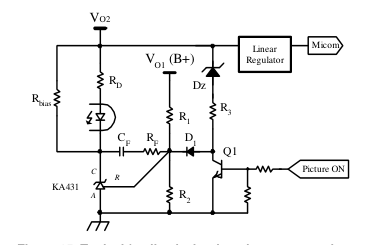
Figure 15. Typical feedback circuit to drop output voltage
in standby mode
Figure 16 shows the burst mode operation waveforms. When the picture ON signal is disabled, Q1 is turned off and R3 and Dz are connected to the reference pin of KA431 through D1. Before Vo2 drops to Vo2stby, the voltage on the reference pin of KA431 is higher than 2.5V, which increases the current through the opto LED. This pulls down the feedback voltage (VFB) of FSCQ0765RT and forces FSCQ0765RT to stop switching. If the switching is disabled longer than 1.4ms, FSCQ0765RT enters into burst operation and the operating current is reduced from 4mA (IOP) to 0.35mA (IOB). Since there is no switching, Vo2 decrease until it reaches Vo2stby. As Vo2 reaches Vo2stby, the current through
the opto LED decreases allowing the feedback voltage to rise. When the feedback voltage reaches 0.4V, FSCQ0765RT resumes switching with a predetermined peak drain current of 0.9A. After burst switching for 1.4ms, FSCQ0765RT stops switching and checks the feedback voltage. If the feedback voltage is below 0.4V, FSCQ0765RT stops switching until the feedback voltage increases to 0.4V. If the feedback voltage is above 0.4V, FSCQ0765RT goes back to the normal operation.
Page 17
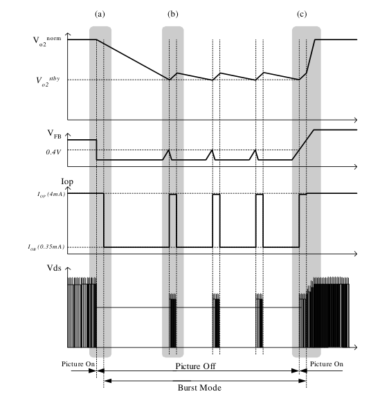
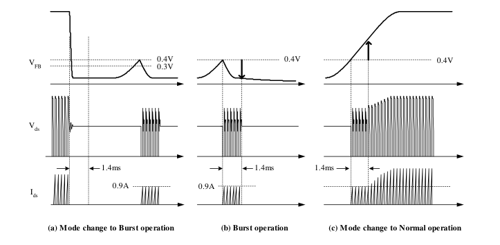
Figure 16. Waveforms of burst operation
Page 18
Typical application circuit
| Application | Output power | Input voltage | Output voltage (Max current) |
|---|---|---|---|
| C-TV | 83W | Universal input (85-265Vac) | 12V (1A) 18V (0.5A) 125V (0.4A) 24V (0.5A) |
Features
- High efficiency (>80% at 85Vac input)
- Wider load range through the extended quasi-resonant operation
- Low standby mode power consumption (<1W)
- Low component count
- Enhanced system reliability through various protection functions
- Internal soft-start (20ms)
Key Design Notes
- 24V output is designed to drop to around 8V in standby mode
1. Schematic
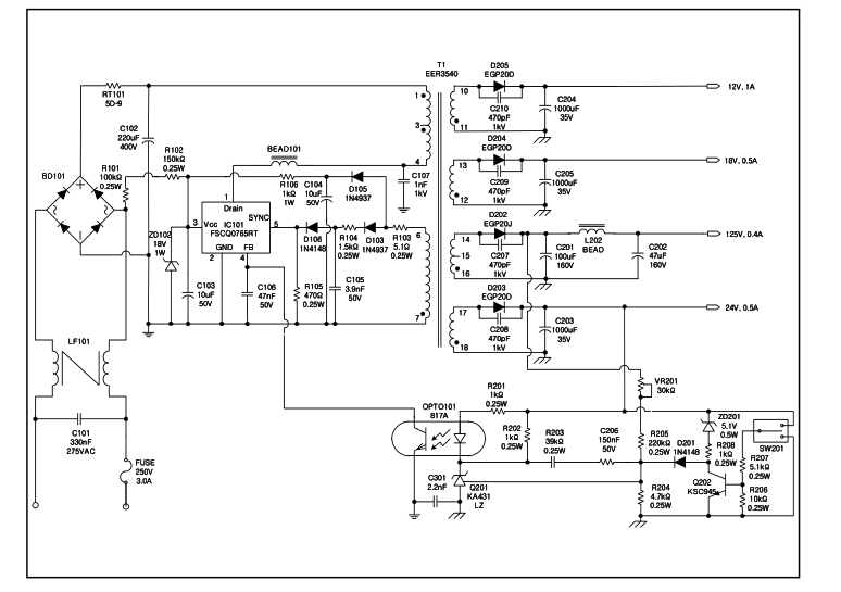
Page 19
- Transformer Schematic Diagram
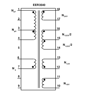
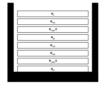
3.Winding Specification
| No | Pin (s→f) | Wire | Turns | Winding Method |
| Np1 | 1 - 3 | 0.5φ × 1 | 32 | Center Winding |
| N125V/2 | 16 - 15 | 0.5φ × 1 | 32 | Center Winding |
| N24V | 18 - 17 | 0.4φ × 2 | 13 | Center Winding |
| N12V | 12 - 13 | 0.5φ × 2 | 7 | Center Winding |
| Np2 | 3 - 4 | 0.5φ × 1 | 32 | Center Winding |
| N125V/2 | 15 - 14 | 0.5φ × 1 | 32 | Center Winding |
| N18V | 11 - 10 | 0.4φ × 2 | 10 | Center Winding |
| Na | 7 - 6 | 0.3φ × 1 | 20 | Center Winding |
4.Electrical Characteristics
| Pin | Specification | Remarks | |
| Inductance | 1 - 3 | 515uH ± 5% | 1kHz, 1V |
| Leakage Inductance | 1 - 3 | 10uH Max | 2nd all short |
- Core & Bobbin Core : EER 3540 Bobbin : EER3540 Ae : 107 mm2
Page 20
6.Demo Circuit Part List
| Part | Value | Note | Part | Value | Note |
|---|---|---|---|---|---|
| Fuse | C210 | 470pF / 1kV | Ceramic Capacitor | ||
| FUSE | 250V / 3A | C301 | 3.3nF / 1kV | AC Ceramic Capacitor | |
| NTC | Inductor | ||||
| RT101 | 5D-9 | BEAD101 | BEAD | ||
| Resistor | BEAD201 | 5uH | 3A | ||
| R101 | 100kΩ | 0.25 W | Diode | ||
| R102 | 150kΩ | 0.25 W | D101 | 1N4937 | 1A, 600V |
| R103 | 5.1Ω | 0.25 W | D102 | 1N4937 | 1A, 600V |
| R104 | 1.5kΩ | 0.25 W | D103 | 1N4148 | 0.15A, 50V |
| R105 | 470Ω | 0.25 W | D104 | Short | |
| R106 | 1kΩ | 1 W | D105 | Open | |
| R107 | Open | ZD101 | 1N5246 | 18V, 1W | |
| R201 | 1kΩ | 0.25 W | ZD102 | Open | |
| R202 | 1kΩ | 0.25 W | ZD201 | 1N5231 | 5.1V, 0.5W |
| R203 | 39kΩ | 0.25 W | D201 | 1N4148 | 0.15A, 50V |
| R204 | 4.7kΩ | 0.25 W , 1% | D202 | EGP20J | 2A, 600V |
| R205 | 220kΩ | 0.25 W , 1% | D203 | EGP20D | 2A, 200V |
| R206 | 10kΩ | 0.25 W | D204 | EGP20D | 2A, 200V |
| R207 | 5.1kΩ | 0.25 W | D205 | EGP20D | 2A, 200V |
| R208 | 1kΩ | 0.25 W | |||
| VR201 | 30kΩ | Bridge Diode | |||
| Capacitor | BD101 | GSIB660 | 6A, 600V | ||
| C101 | 330n/275VAC | Box Capacitor | Line Filter | ||
| C102 | 220uF / 400V | Electrolytic | LF101 | 14mH | |
| C103 | 10uF / 50V | Electrolytic | Transformer | ||
| C104 | 10uF / 50V | Electrolytic | T101 | EER3540 | |
| C105 | 3.9nF / 50V | Film Capacitor | Switch | ||
| C106 | 47nF / 50V | Film Capacitor | SW201 | ON/OFF | For MCU Signal |
| C107 | 1nF / 1kV | Film Capacitor | IC | ||
| C108 | Open | IC101 | FSCQ0765RT | TO220F-5L | |
| C201 | 100uF / 160V | Electrolytic | OPT101 | 817A | |
| C202 | 47uF / 160V | Electrolytic | Q201 | KA431LZ | TO-92 |
| C203 | 1000uF / 35V | Electrolytic | Q202 | KSC945 | |
| C204 | 1000uF / 35V | Electrolytic | |||
| C205 | 1000uF / 35V | Electrolytic | |||
| C206 | 150nF / 50V | Film Capacitor | |||
| C207 | 470pF / 1kV | Ceramic Capacitor | |||
| C208 | 470pF / 1kV | Ceramic Capacitor | |||
| C209 | 470pF / 1kV | Ceramic Capacitor | |||
Page 21
- Layout
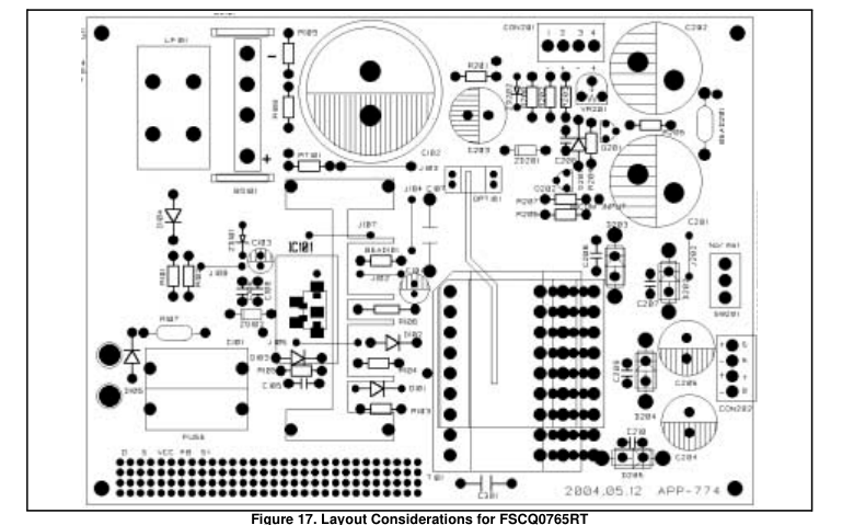
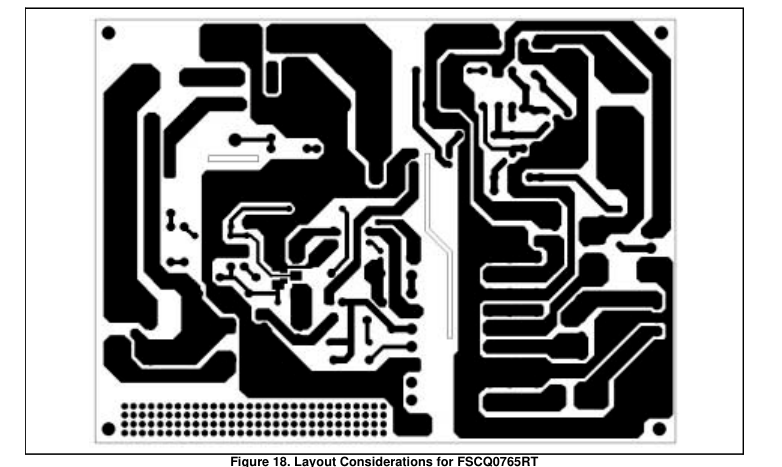
Page 22
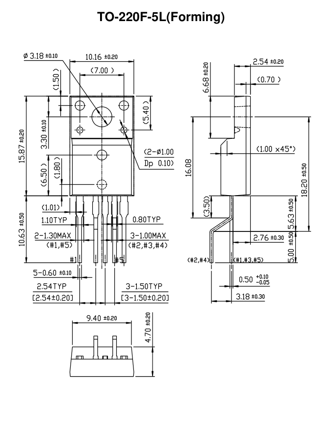
Package Dimensions
Dimensions in Millimeters
Page 23
Ordering Information
| Product Number | Package | Marking Code | BVdss | Rds(ON) Max. |
|---|---|---|---|---|
| FSCQ0765RTYDTU | TO-220F-5L(Forming) | CQ0765RT | 650V | 1.6 Ω |
YDTU : Forming Type
Page 24


LIFE SUPPORT POLICY
FAIRCHILD’S PRODUCTS ARE NOT AUTHORIZED FOR USE AS CRITICAL COMPONENTS IN LIFE SUPPORT DEVICES OR SYSTEMS WITHOUT THE EXPRESS WRITTEN APPROVAL OF THE PRESIDENT OF FAIRCHILD SEMICONDUCTOR CORPORATION. As used herein: 1. Life support devices or systems are devices or systems which, (a) are intended for surgical implant into the body, or (b) support or sustain life, and (c) whose failure to perform when properly used in accordance with instructions for use provided in the labeling, can be reasonably expected to result in a significant injury of the user.
www.fairchildsemi.com
- A critical component in any component of a life support device or system whose failure to perform can be reasonably expected to cause the failure of the life support device or system, or to affect its safety or effectiveness.
7/7/04 0.0m 001
2004 Fairchild Semiconductor Corporation