


 Download PDF
FRG RFE
Document overview
- PDF pages: 3
Technical content
Page 1
| NO. | PQ08-101E | |||
| Product Specification and Approval Sheet | Version | 1 | Page | 1/3 |
Radial Leaded PTC Resettable Fuse: FRG Series
1. Summary
(a) RoHS Compliant (Lead Free) Product (b) Applications: Wide variety of electronic equipment (c) Product Features: Very Low resistance, Very High hold current, Solid state, Radial
leaded product ideal for up to 16VDC
(d) Operation Current: 2.5A~14.0A (e) Maximum Voltage: 16VDC (f) Temperature Range: -40℃ to 85℃
2. Agency Recognition
UL: File No. E211981 C-UL: File No. E211981 TÜV: File No. R50004084
3. Electrical Characteristics (23℃)
| Part Number | Hold Current | Trip Current | Max. Time to trip | Max. Current | Rated Voltage | Typ. Power | Resistance | |
|---|---|---|---|---|---|---|---|---|
| R MIN | R1 MAX | |||||||
| I , A H | I , A T | at 5XI H, S | I , A MAX | V , V MAX DC | Pd, W | Ohm | Ohm | |
| FRG250-16F | 2.5 | 4.7 | 5.0 | 100 | 16 | 1.0 | 0.022 | 0.053 |
| FRG300-16F | 3.0 | 5.1 | 2.0 | 100 | 16 | 2.3 | 0.034 | 0.105 |
| FRG400-16F | 4.0 | 6.8 | 3.5 | 100 | 16 | 2.4 | 0.020 | 0.063 |
| FRG500-16F | 5.0 | 8.5 | 3.6 | 100 | 16 | 2.6 | 0.014 | 0.044 |
| FRG600-16F | 6.0 | 10.2 | 5.8 | 100 | 16 | 2.8 | 0.009 | 0.033 |
| FRG700-16F | 7.0 | 11.9 | 8.0 | 100 | 16 | 3.0 | 0.006 | 0.021 |
| FRG800-16F | 8.0 | 13.6 | 9.0 | 100 | 16 | 3.0 | 0.005 | 0.018 |
| FRG900-16F | 9.0 | 15.3 | 12.0 | 100 | 16 | 3.3 | 0.004 | 0.015 |
| FRG1000-16F | 10.0 | 17.0 | 12.5 | 100 | 16 | 3.3 | 0.003 | 0.012 |
| FRG1100-16F | 11.0 | 18.7 | 13.5 | 100 | 16 | 3.7 | 0.003 | 0.010 |
| FRG1200-16F | 12.0 | 20.4 | 16.0 | 100 | 16 | 4.2 | 0.002 | 0.009 |
| FRG1400-16F | 14.0 | 23.8 | 20.0 | 100 | 16 | 4.6 | 0.002 | 0.008 |
IH=Hold current-maximum current at which the device will not trip at 23℃ still air. IT=Trip current-minimum current at which the device will always trip at 23℃ still air. IMAX= Maximum fault current device can withstand without damage at rated voltage (VMAX). VMAX=Maximum voltage device can withstand without damage at its rated current. Pd=Typical power dissipated from device when in the tripped state in 23℃ still air environment. RMIN=Minimum device resistance at 23℃. R1MAX=Maximum device resistance at 23℃ 1 hour after tripping. Physical specifications: Lead material: FRG250-16F Tin plated copper clad steel, 24 AWG. Lead material: FRG300-16F~FRG1100-16F Tin plated copper, 20 AWG.
Lead material: FRG1200-16F~FRG1400-16F Tin plated copper,18 AWG. Soldering characteristics: MIL-STD-202, Method 208E. Insulating coating: Flame retardant epoxy, meet UL-94V-0 requirement.
Page 2
| NO. | PQ08-101E | |||
| Product Specification and Approval Sheet | Version | 1 | Page | 2/3 |
4. Production Dimensions (millimeter)
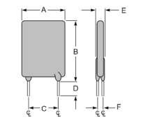
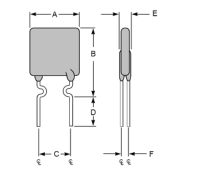
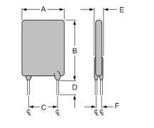
Figure 2
Figure 1
Figure 3
Lead Size: 20AWG
Lead Size: 24AWG
Lead Size: 18AWG
φ0.81 mm Diameter
φ0.51 mm Diameter
φ1.0 mm Diameter
| Part Number | Fig | A | B | C | D | E | F |
|---|---|---|---|---|---|---|---|
| Maximum | Maximum | Typical | Minimum | Maximum | Typical | ||
| FRG250-16F | 1 | 8.9 | 12.8 | 5.1 | 7.6 | 3.0 | 1.2 |
| FRG300-16F | 2 | 7.1 | 11.0 | 5.1 | 7.6 | 3.0 | 1.2 |
| FRG400-16F | 2 | 8.9 | 12.8 | 5.1 | 7.6 | 3.0 | 1.2 |
| FRG500-16F | 2 | 10.4 | 14.3 | 5.1 | 7.6 | 3.0 | 1.2 |
| FRG600-16F | 2 | 10.7 | 17.1 | 5.1 | 7.6 | 3.0 | 1.2 |
| FRG700-16F | 2 | 11.2 | 19.7 | 5.1 | 7.6 | 3.0 | 1.2 |
| FRG800-16F | 2 | 12.7 | 20.9 | 5.1 | 7.6 | 3.0 | 1.2 |
| FRG900-16F | 2 | 14.0 | 21.7 | 5.1 | 7.6 | 3.0 | 1.2 |
| FRG1000-16F | 2 | 16.5 | 24.1 | 5.1 | 7.6 | 3.0 | 1.2 |
| FRG1100-16F | 2 | 17.5 | 26.0 | 5.1 | 7.6 | 3.0 | 1.2 |
| FRG1200-16F | 3 | 17.5 | 28.0 | 10.2 | 7.6 | 3.6 | 1.4 |
| FRG1400-16F | 3 | 27.9 | 27.9 | 10.2 | 7.6 | 3.6 | 1.4 |
5. Thermal Derating Curve
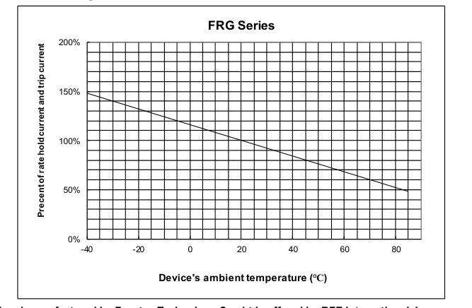
Page 3
| NO. | PQ08-101E | |||
| Product Specification and Approval Sheet | Version | 1 | Page | 3/3 |
6. Typical Time-To-Trip at 23℃
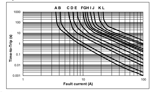
A = FRG250-16F
B = FRG300-16F
C = FRG400-16F
D = FRG500-16F
E = FRG600-16F
F = FRG700-16F
G = FRG800-16F
H = FRG900-16F
I = FRG1000-16F
J = FRG1100-16F
K = FRG1200-16F
L = FRG1400-16F
7. Material Specification
Lead material: FRG250-16F Tin plated copper clad steel, 24 AWG.
Lead material: FRG300-16F~FRG1100-16F Tin plated copper, 20 AWG.
Lead material: FRG1200-16F~FRG1400-16F Tin plated copper, 18 AWG.
Soldering characteristics: MIL-STD-202, Method 208E.
Insulating coating: Flame retardant epoxy, meets UL-94V-0 requirement.
8. Part Numbering and Marking System
Part Numbering System Part Marking System
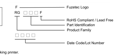
F R G □ □ □ ─ □ □ F
F
RoHS Compliant / Lead Free
RG300F
Voltage Rating
93BD
Current Rating
Example
Note: Font on Marking may look slightly different due to fine turnings of each Marking printer.
Warning: - Each product should be carefully evaluated and tested for their suitability of application.
- Operation beyond the specified maximum rating or improper use may result in damage and possible electrical arcing and/or flame. - PPTC device are intended for occasional overcurrent protection. Application for repeated overcurrent condition and/or prolonged trip are not anticipated. - Avoid contact of PPTC device with chemical solvent, including some inert material such as silicone based oil, lubricant and etc. Prolonged contact will damage the device performance. - Additional protection mechanism are strongly recommended to be used in conjunction with the PPTC device for protection against abnormal or failure conditions. - Avoid use of PPTC device in a constrained space such as potting material, housing and containers where have limited space to
accommodate device thermal expansion and/or contraction.