
FP2-S047-R ETC2
Document overview
- Manufacturer or author: Provided By www.digicamel.com(FREE DATASHEET DOWNLOAD SITE)
- PDF pages: 4
Technical content
0714 Page 1 of 4 D ata Sheet PM -4110
Description
- 125°C maximum total temperature operation
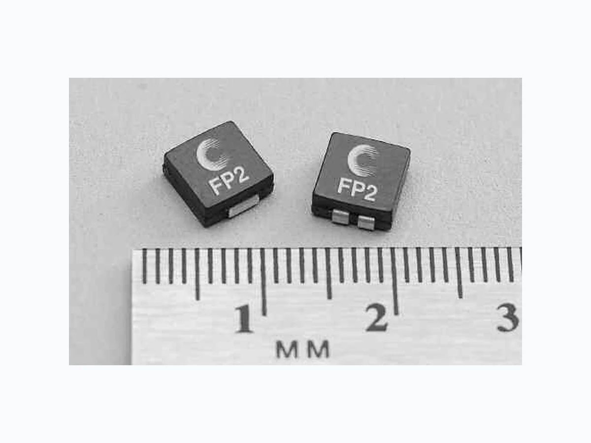
- Surface mount inductors designed for higher speed switch mode applications requiring lower inductance and high current
- Dual conductors allow for low inductance and high current or high inductance and lower current
- Inductance range from .047uH to 0.480uH
- Current range up to 42 Amps
- Meets UL 94V-0 flammability standard
- Ferrite core material
Applications
- Next generation microprocessors Environmental Data
- Storage temperature range: -40°C to +125°C
- Operating ambient temperature range: -40°C to +125°C (range is application specific).
- Solder reflow temperature: +260°C max. for 10 seconds max. Packaging
- Supplied in tape and reel packaging, 1700 (FP2-S and FP2-D) and 950 (FP2-S200 and FP2-VXXX) per reel Parallel Mode Part Inductance OCL (1) I rMS (2) I SAT (3) DCr (4) Height Volt-µ Number µH µH ± Amps Amps Ω Sec (VµS) (rated) 15% nom. ref.(5) Single Conductor Double Conductor Series Mode Part Inductance OCL (1) I rMS (2) I SAT (3) DCr (4) Height Volt-µ (5) Number µH ref. µH Amps Amps Ω Sec (VµS) (rated) ref. ref. ref. Double Conductor Notes: (1) Open Circuit Inductance Test Parameters: 1MHz, 0.25V rms , 0.0Adc. (2) RMS current for an approximate ∆T of 40°C without core loss. It is recommended that the temperature of the part not exceed 125°C. (3) Peak current for approximately 30% rolloff at 20°C. (4) DCR limits 20°C. (5) Applied Volt-Time product (V-µS) across the inductor. This value represents the applied V-µS at 500kHz necessary to generate a core loss equal to 10% of the total losses for 40°C temperature rise. FLAT-PAC™ Low Profile Inductors (Surface Mount)
0714 Page 2 of 4 D ata Sheet PM -4110
Notes: (1) Marking SXXX = S: Single Conductor Style, DXXX = D: Dual Conductor Style, XXX - last three digits of part number. Date Code: yww = y: Last Digit of year, ww: week of year. (2) All Dimensions are in millimeters unless otherwise specified. (3) For parallel mode operation, connect terminals 1 to 4 and 2 to 3 on PCB (use Single Conductor PCB Layout) For series mode operation, connect terminals 2 to 4 on PCB (Dual Conductor Model). 6.70 Max 7.20 Max (S or V)XXX yww TOP VIEW 2.50 (2x) 7.50 6.50 (4x) PCB PAD LAYOUT SCHEMATIC 3.0 ref. Height mm Max 1.30 ref. (2x) FRONT VIEW SIDE VIEW 1.0 min. (2x) Dual Conductor 6.70 Max yww 7.20 Max DXXX TOP VIEW PCB PAD LAYOUT 2.50 (2x) 7.50 3.00 (4x) 0.50
2 Winding Mode
2.50 (2x) 7.50 3.00 (4x) 0.50 (typ) Series Mode 4.50 (2x) 1.50 1 4 2 3 1 4 2 3 3.00 mm Max 1.30 ref. (2x) FRONT VIEW 1.25 (2x) ref. 1.00 ref. SCHEMATIC Winding 1 Winding 2 SIDE VIEW (4x) Packaging Information Ko
1.5 Dia□
min. Bo Ao 12.0 4.0 2.0 1.5 Dia.□ +0.1/-0.0 A A 1.75 7.5 16.0□ +/-0.3 Ao=6.6mm Bo=7.1mm Ko=3.2mm Ko=5.2mm (FP2?S200 & FP2V) ACTUAL SIze FLAT-PAC’S FLAT-PAC™ Low Profile Inductors (Surface Mount) Direction of Feed ©
0714 Page 3 of 4 D ata Sheet PM -4110
FLAT-PAC™ Low Profile Inductors (Surface Mount) Core Loss IRMS DERATING WITH CORE LOSS 100080060050040030020010080605040302010 % of Applied Volt-µ-Seconds % of Losses from Irms (maximum) 1MHz 500KHz 300KHz 200KHz 100KHz Inductance Characteristics
0714 Page 4 of 4 D ata Sheet PM -4110
FLAT-PAC™ Low Profile Inductors (Surface Mount) Visit us on the Web at www.eaton.com/elx eaton’s electrical Group electronics Division
1225 Broken Sound Parkway NW
Boca Raton, FL 33487-3533 Tel: 1-561-998-4100 Fax: 1-561-241-6640 Toll Free: 1-888-414-2645 The only controlled copy of this Data Sheet is the electronic read?only version located on the Bussmann Network Drive. All other copies of this document are by definition uncontrolled. This bulletin is intended to clearly present comprehensive product data and provide technical information that will help the end user with design applications. Bussmann reserves the right, without notice, to change design or construction of any products and to discontinue or limit distribution of any products. Bussmann also reserves the right to change or update, without notice, any technical information contained in this bulletin. Once a product has been selected, it should be tested by the user in all possible applications. Life Support Policy: Bussmann does not authorize the use of any of its products for use in life support devices or systems without the express written approval of an officer of the Company. Life support systems are devices which support or sustain life, and whose failure to perform, when properly used in accordance with instructions for use provided in the labeling, can be reasonably expected to result in significant injury to the user. PM -4110 0714