
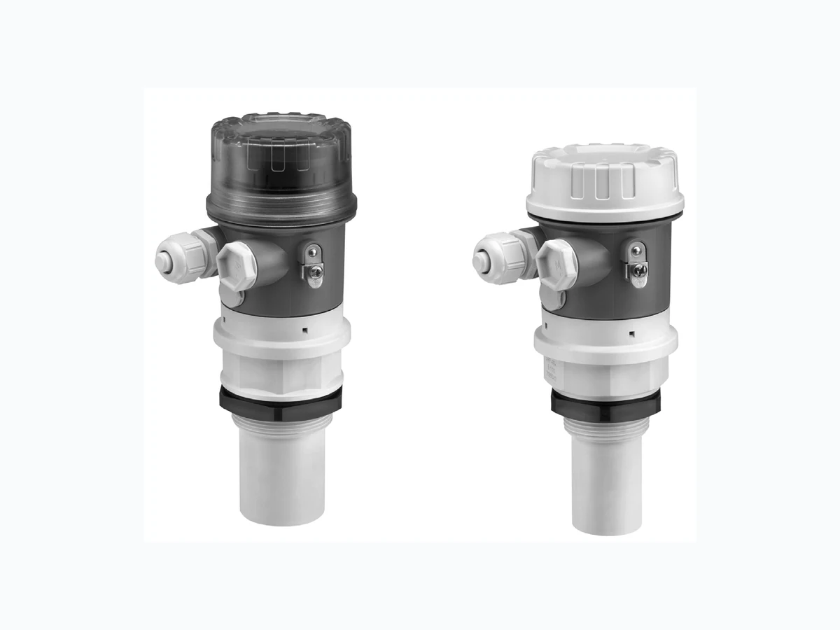
TI00440F EH
Document overview
- Manufacturer or author: Provided By www.digicamel.com(free datasheet download site)
- PDF pages: 28
Technical content
TI00440F/00/EN/15.14 71225633 Technical Information Prosonic T FMU30 Ultrasonic Level Measurement Compact transmitters for non-contact level measurement of fluids, pastes and coarse bulk materials Application
- Continuous, non-contact level measurement in fluids, pastes, sullages and coarse bulk materials
- System integration via 4 to 20mA
- Maximum measuring range: – 1½" sensor: 5 m (16 ft) in fluids 2 m (6 ft) in bulk materials – 2" sensor: 8 m (26 ft) in fluids 3.5 m (11 ft) in bulk materials Features and benefits
- Quick and simple commissioning via menu-guided on- site operation with four-line plain text display; 7 languages selectable
- Envelope curves on the on-site display for simple diagnosis
- Linearization function (up to 32 points) for conversion of the measured value into any unit of length, volume or flow rate
- Non-contact measurement method minimizes service requirements
- Installation possible from thread G 1½“ or NPT 1½“ upwards
- Integrated temperature sensor for automatic correction of the temperature dependent sound velocity
2 Endress+Hauser
Function and system design Measuring principle L00-FMU30-15-00-00-xx-001 BD Blocking distance D Distance from sensor membrane - product surface E Empty distance F Span (full distance) L Level Time-of-flight method The sensor of the instrument transmits ultrasonic pulses in the direction of the product surface. There, they are reflected back and received by the sensor. The instrument measures the time t between pulse transmission and reception. The instrument uses the time t (and the velocity of sound c) to calculate the distance D between the sensor membrane and the product surface: D = c t/2 As the device knows the empty distance E from a user entry, it can calculate the level as follows: L = E - D An integrated temperature sensor (NTC) compensates for changes in the velocity of sound caused by temperature changes. Interference echo suppression The interference echo suppression feature on the instrument ensures that interference echos (e.g. from edges, welded joints and installations) are not interpreted as a level echo. Calibration Enter the empty distance E and the span F to calibrate the device. Blocking distance Span F may not extend into the blocking distance BD. Level echos within the blocking distance cannot be evaluated due to the transient characteristics of the sensor. 20 mA 100% 4m A D L E F BD Sensor BD Max. range fluids Max. range bulk materials 1½" 0.25 m (0.8 ft) 5 m (16 ft) 2 m (6.6 ft) 2" 0.35 m (1.1 ft) 8 m (26 ft) 3.5 m (11 ft)
4 Endress+Hauser
Equipment architecture The complete measuring system consists of: L00-FMU30xxx-14-00-06-xx-008
1 PLC (programmable logic controller)
2 Computer with operating tool (e.g. FieldCare)
3 Commubox FXA291 and ToF Adapter FXA291
4 Operating and display module
5 Prosonic FMU30
6 Transmitter power suppl y unit RMA42 or RN221N
- With display and operating module
- With a PC, Commubox FXA291 + ToF Adapter FX A291 and the operating software FieldCare ENDRESS + HAUSER RMA 422 E 1 2
Measured variable The distance D between the sensor membrane and the product surface is measured, see also figure ä 3. Using the linearization function, the device uses D to calculate:
- Level L in any units
- Volume V in any units
- Flow Q across measuring weirs or open channels in any units Measuring range The measuring range is limited by the range of a sensor. The sensor range is, in turn, dependent on the operating conditions. To estimate the actual range, proceed as follows (see also the calculation example in the diagram): 1. Determine which of the influences shown in the following table are appropriate for your process. 2. Add the corresponding attenuation values. 3. From the total attenuation, use th e diagram to calculate the range. Fluid surface Attenuation Calm 0 dB Waves 5 to 10 dB Strong turbulence (e.g. stirrers) 10 to 20 dB Foaming Please contact your Endress+Hauser sales representative. Bulk material surface Attenuation Hard, rough (e.g. rubble) 40 dB Soft (e.g. peat, dust-covered clinker) 40 to 60 dB Dust Attenuation No dust formation 0 dB Little dust formation 5 dB Heavy dust formation 5 to 20 dB Filling curtain in detection range Attenuation None 0 dB Small quantities 5 to 10 dB Large quantities 10 to 40 dB Temperature difference between sensor and product surface Attenuation to 20 °C (68 °F) 0 dB to 40 °C (104 °F) 5 to 10 dB to 60 °C (140 °F) 10 to 15 dB
6 Endress+Hauser
L00-FMU3xxxx-05-00-00-xx-100 1S e n s o r 2 " 2S e n s o r 1 ½ " A Attenuation (dB) R Range (m) Example These measuring conditions have been taken into account during the calculation of the maximum measuring range in solid applications. Operating frequency Output Output signal 4 to 20 mA Signal on alarm Error information can be accessed via the following interfaces:
- On-site display (error symbol, erro r code and plain text description)
- Current output, signal on error can be select ed (e.g. according to NAMUR recommendation NE43) Output damping Freely selectable, 0 to 255 s Linearization The linearization function of the instrument allows conversion of the measured value into any unit of length or volume. In open channels or measuring weirs, also a flow linearization is possible (calculation of the flow from the measured level). The linearization table for calculating the volume in an horizontal cylindrical tank is preprogrammed. You can also enter any number of other tables containing up to 32 value pairs either manually or semi-automatically (by filling the vessel under controlled conditions). 10 20 30 40 50 60 70 80 A [dB] R [m]
- Strong turbulence surface approx. 50 dB
- N o d u s t f o r m a t i o n 0 d B
- Filling curtain in detection range 10 dB
- Temperature diff. < 20 °C (68 °F) 0 dB approx. 50 dB range approx. 3.5 m (11 ft) for FMU30 2" sensor 1½" sensor 2" sensor approx. 70 kHz approx. 50 kHz
Terminal compartment The terminals are located underneath the housing cover. L00-FMU30xxx-04-00-00-xx-001
1 Terminals
2 Optional: display
3 Internal earth terminal
4 External earth terminal
L00-FMU30xxx-04-00-00-de-015 1P o w e r 2 Fuse as per IEC 60127, T 0.5 A
3 Plant ground
3 4...20 mA in the terminal compartment.
- A standard installation cable is sufficient for the connection.
- Protective circuitry against reverse polarity, RFI and ov er-voltage peaks is built into the device (see also Technical Information TI00241F/00/EN "EMC Test Procedures") 1 2 Display L- L+ 123 2T 0.5A
8 Endress+Hauser
Terminals Cable cross-section: 0.25 to 2.5 mm2 (24 to 14 AWG) Cable entry G ½" or ½" NPT Cable gland M20x1.5 (recommended cable diameter 6 to 10 mm (0.24 to 0.39 in)) Power consumption 51 mW to 800 mW Current consumption 3.6 to 22 mA Performance characteristics Reaction time The reaction time depends on the parameter settings. The minimum value is: min. 2 s Reference operating conditions
- Temperature = +20 °C (+68 °F)
- Pressure = 1013 mbar abs. (15 psi abs.)
- Humidity = 50 %
- Ideal reflective surface (e.g. calm, smooth fluid surface)
- No interference reflections within signal beam
- Set application parameters: – Tank shape = dome ceiling – Medium property = liquid – process conditions = standard liquid Measured value resolution 1 mm (0.04 in) Pulse frequency max. 0.5Hz The exact values are dependent on the type of device and the parameter settings. Maximum measuring error 1) 2) ±0.2 % of the maximum span of the sensor Typical measuring error Include linearity, repeatability, and hysteresis Better than: ±3 mm (±0.12 in) or 0.2 % of measuring distance* * whichever is greater Influence of the vapor pressure The vapor pressure at 20 °C (68 °F) gives a hint on the accuracy of the ultrasonic level measurement. If the vapor pressure at 20 °C (68 °F) is below 50 mbar (1 psi), ultrasonic level measurement is possible with a very high accuracy. This is valid for water, aqueous solutions, water-solid-solutions, dilute acids (hydrochloric acid, High vapor pressures or outgassing media (ethanol, acetone, ammonia, ...) can influence the accuracy. If conditions like these are present, please contact your Endress+Hauser sales representative. 1) according to EN 61298-2 2) with reference operating conditions
L00-FMU30xxx-17-00-00-xx-002 A Installation with counter nut 1 counter nut (PC) supplied for G1½ and G2 instruments B Installation with sleeve 1 sealing (EPDM) supplied C Installation with installation bracket D Installation with screw in flange 1 sealing (EPDM) supplied 2 nozzle 3s e n s o r 4 screw in flange For installation bracket or screw in flange ä 22, "Accessories". BA C D
10 Endress+Hauser
Installation conditions for level measurements L00-FMU30xxx-17-00-00-xx-005
- Do not install the sensor in the middle of the tank (3). We recommend leaving a distance between the sensor and the tank wall (1) measuring 1/6 of the tank diameter.
- Protect the device against direct sun or rain (2) ä 26 "Weather protection cover".
- Avoid measurements through the filling curtain (4).
- For solid application where bulk solid cones appear, align the sensor membrane perpendicular to the surface.
- Make sure that equipment (5) such as limit switches, temperature sensors, etc. are not located within the emitting angle . In particular, symmetrical equipment (6) such as heating coils, baffles etc. can influence measurement.
- Never install two ultrasonic measuring devices in a tank, as the two signals may affect each other.
- To estimate the detection range, use the 3 dB emitting angle . Installation in narrow shafts 234 1/6D D r /c97 L Sensor Lmax rmax 1½" 11° 5 m (16 ft) 0.48 m (1.6 ft) 2" 11° 8 m (26 ft) 0.77 m (2.5 ft) In narrow shafts with strong interference echoes, we recommend using an ultrasound guide pipe (e.g. PE or PVC wastewater pipe) with a minimum diameter of 100 mm (3.94 in). Make sure that the pipe is not soiled by accumulated dirt. If necessary, clean the pipe at regular intervals. L00-FMU30xxx-17-00-00-xx-010
1 Venting hole
Installation conditions for flow measurements
- Install the instrument at the inflow side (B), as close above the maximum water level Hmax as possible (take into account the blocking distance BD).
- Position the instrument in the middle of the channel or weir.
- Align the sensor membrane parallel to the water surface.
- Keep to the installation distance of the channel or weir. Example: Khafagi-Venturi flume A0019607 A Khafagi-Venturi flume BD Blocking distance B Inflow E Empty calibration C Outflow F Full calibration V Direction of flow Example: Triangular weir L00-FMU30xxx-17-00-00-xx-012 BD Blocking distance E Empty calibration F Full calibration 1 x b0 BD A E BC VHmax =F (= F) min. 3 H H min. 2 H /c97 min. 2 H BD E max. max. max. max.
12 Endress+Hauser
Blocking distance, nozzle installation Install the instrument at a height so that the blocking distance BD is not undershot, even at maximum fill level. Use a pipe nozzle if you cannot maintain the blocking distance in any other way. The interior of the nozzle must be smooth and may not contain any edges or welded joints. In particular, there should be no burr on the inside of the tank side nozzle end. Note the specified limits for nozzle diameter and length. To minimise disturbing factors, we recommend an angled socket edge (ideally 45°). L00-FMU30xxx-17-00-00-xx-004 BD Blocking distance F Full calibration (span) SD Safety distance D Nozzle diameter E Empty calibration L Nozzle length Caution! If the blocking distance is undershot, it may cause device malfunction. Note! In order to notice if the level approaches the blocking distance, you can specify a safety distance (SD). If the level is within this safety distance, the instrument outputs a warning or alarm message. F E BD SD L D Maximum nozzle length mm (in) Nozzle diameter 1½" sensor 2" sensor Sensor characteristics Emitting angle 11° 11° Blocking distance (m [ft]) 0.25 (0.8) 0.35 (1.1) Max. range (m [ft]) in liquids 5 (16) 8 (26) Max. range (m [ft]) in solids 2 (6.6) 3.5 (11)
Ambient temperature range 20 °C to +60 °C (4 °F to +140 °F) Use a protective cover, in order to protect the sensor from direct sun or rain ä 26, "Weather protection cover". Storage temperature 40 °C to +80 °C (40 °F to +176 °F) Resistance to alternating temperature cycles To DIN EN 60068-2-14; Nb test : +60°C/ 20°C (+140 °F/4 °F), 0.5K/min, 100cycles Climate class DIN EN 60068-2-38 (Test Z/AD) DIN/IEC 68 T2-30Db Ingress protection • With closed housing, tested according to – IP68, 24h at 1.83 m (6.0 ft) under water surface – IP66
- With open housing: IP20 (also ingre ss protection of the display) Vibration resistance DIN EN 60068-2-64 / IEC 68-2-64: 20 to 2000 Hz, 1 (m/s)2/Hz; 3 x 100 min Electromagnetic compatibility (EMC)
- Electromagnetic compatibility to EN 61326. For deta ils refer to the declaration of conformity.
- With regard to interference immunity the requ irements for "industrial environment" are met.
- Influence of EMC < 1 % FS Process Process temperature range 20°C to +60°C ( 4 °F to +140 °F) A temperature sensor is integrated in the sensor for correction of the temperature-dependent time-of-flight. Process pressure range 0.7 bar to 3 bar abs. (10.15 psi to 43.5 psi)
14 Endress+Hauser
Design; dimensions L00-FMU30xxx-06-00-00-xx-006 A Sensor 1½" B Sensor 2" Weight Housing design Type of housing F16 plastic housing Cover Plastic cover
- For version without on-site display (low, grey)
- For version with on-site display (high, transparent) Process connection G 1½ NPT " 234 (9.21) mm (in) 81 (3.19) 82 (3.23) 26(1.02) ø50 (1.97) 238 (9.37)G 2 NPT " ø39 (1.54) (1.02) ø85 ( 3.35)ø max. 76 (2.99) max. 76 (2.99) ø85 ( 3.35)ø AB 65 mm 65 mm Sensor Weight 1½" approx. 0.75 kg (1.65 lbs) 2" approx. 0.8 kg (1.76 lbs) Sensor Process connection 1½" • Thread G 1½“, PP
- Thread MNPT 1½“ - 11.5 2" • Thread 2", PP
- Thread MNPT 2" - 11.5
L00-FMU3xxxx-16-00-00-xx-001 Note! The chemical compatibility of the sensors must be checked before installation with compatibility charts. Pos. Part Material Cover (grey) PBT Cover (transparent) PA O-ring EPDM
2 Ground terminal:
304 (1.4301) 301 (1.4310)
3 Nameplate Polyester
5 Sensor (in contact with process) PP
6 Matching Layer (in cont act with process) EPDM
7 Counter nut (in contact with process) PC
8 Sealing (in contact with process) EPDM
9 Sealing EPDM
10 Adapter of housing PBT GF 30-FR
11 Goretex filter PBT-20GF / grey RAL7035
Cable gland Polyamid (PA) Plug PBT-GF30
13 Housing PBT-FR
16 Endress+Hauser
The LCD module for display and operation is located beneath the housing cover. Open the cover to operate the device. L00-FMU30xxx-07-05-xx-xx-000
1 Display symbol
2 Display (rotatable)
3 Plug-in module
4 Function keys
4...20mA FEU31 Display E 1 2 Symbol in display continuous flashing Meaning Alarm Warning Security Locking
Key(s) Meaning (The keys to press are displayed in grey.) Navigate upwards in the selection list Edit numeric value within a function Navigate downwards in the selection list Edit numeric value within a function Navigate to the left within a function group Navigate to the right within a function group, confirmation. or Contrast settings of the LCD Hardware lock / unlock After a hardware lock, an operation of the instrument via display or communication is not possible! The hardware can only be unlocked via the display. An unlock parameter must be entered to do so (unlock parameter: 100).
18 Endress+Hauser
On-site operation Operation The LC-Display allows configuration via 3 keys directly at the instrument. All device functions can be set through a menu system. The menu consists of function groups and functions. Within a function, application parameters can be read or adjusted. The user is guided through a complete configuration procedure. For ease operation can choose between 7 language: (de: german; en: english; es: spanish; fr: french; it: italian; ja: japanese; nl: dutch). L00-FMU30xxx-07-00-00-en-004 Remote operation Opera tion with FieldCare FieldCare is Endress+Hauser's FDT based Plant Asset Management Tool. It can configure all intelligent field devices in your plant and supports you in managing them. By using status information, it also provides a simple but effective means of checking their health.
- Supports Ethernet, HA RT, PROFIBUS PA, FOUNDATION Fieldbus etc.
- Operates all Endress+Hauser devices
- Operates all third-party actuators, I/O sy stems and sensors supporting the FDT standard
- Ensures full functionality for all devices with DTMs
- Offers generic profile operation for any third-party fieldbus device that does not have a vendor DTM Connection for FMU30:
- Commubox FXA291 and ToF adapter FXA291 (available as accessory) Using the following functions:
- Signal analysis via envelope curve
- Linearization table (graphically supported creation, editing, importing and exporting)
- Loading and saving of instrument data (Upload/Download)
- Documentation of measuring point HOME FG00 F000 F001 F002 F003 F004 ... FG01 FG02 FG03 FG04 FG05 FG06 FG07 ... Headline Po sition indicator Main value UnitSymbol Selection list Function groups -> Functions Help text Envelope curve Bargraph
Menu-guided commissioning: Signal analysis via envelope curve:
20 Endress+Hauser
Certificates and Approvals CE mark The measuring system meets the legal requirements of the EC-guidelines. Endress+Hauser confirms the instrument passing the required tests by attaching the CE-mark. Ex approvals •A T E X
- I E C E x
- C S A C / U S
- N E P S I Additional safety instructions must be observed for applications in hazardous areas. They arecontained in the separate "Safety Instructions" (XA) document, which is included in the scope ofdelivery. Reference is made to the XA on the nameplate of the device. Note! Details on the available certificats as well as the associated XAs can be found in the Associated documentation chapter documentation ä 27. Ex approval The available certificates are listed in the ordering information. Note the associated safety instructions (XA) and control or installation drawings (ZD). External standards and guidelines EN 60529 Protection class of housing (IP-code) EN 61326 series EMC product family standard for electrical equipment for measurement, control and laboratory use NAMUR User association for automation technology in process industries
Ordering information
FMU30 Versions that mutually exclude one another are not marked. You can enter the versions for the specific feature in the following table. The versions entered make up the complete order code. Options which are mutually exclucive are not marked. Endress+Hauser supplies DIN/EN flanges made of stainless steel AISI 316L with the material number 1.4404 or 1.4435. With regard to their temperature stability properties, the materials 1.4404 and 1.4435 are grouped under 13E0 in EN 1092-1 Tab. 18. The chemical composition of the two materials can be identical.
010 Approval:
BB ATEX II 1/2G Ex ia IIC T5 CA CSA C/US General Purpose CB CSA C/US IS CI.I Div.1 Gr.A-D IB IEC Ex zone 0/1, Ex ia IIC T5 Ga/Gb NB NEPSI zone 0/1, Ex ia IIC T5 Ga/Gb
99 Special version
020 Display; Operating:
G W/o; via spare part display FMU30 H Envelope curve display on site; push button Y Special version E Gland M20, IP68 F Thread G1/2, IP68 G Thread NPT1/2, IP68 YS p e c i a l v e r s i o n
040 Sensor; Max Range; Blocking Distance:
AA 1-1/2"; 5m liquid/2m solid; 0.25m AB 2"; 8m liquid/3.5m solid; 0.35m YY Special version
050 Process Connection:
GGF Thread ISO228 G1-1/2, PP GHF Thread ISO228 G2, PP RGF Thread ANSI MNPT1-1/2, PP RHF Thread ANSI MNPT2, PP YYY Special version
620 Accessory Enclosed:
RA UNI flange 2"/DN50/50, PP max 4bar abs/58psia, suitable for 2" 150lbs/DN50 PN16/10K 50 RB UNI flange 2"/DN50/50, PVDF max 4bar abs/58 psia, suitable for 2" 150lbs/DN50 PN16/10K 50 RC UNI flange 2"/DN50/50, 316L max 4bar abs/58psia, suitable for 2" 150lbs/DN50 PN16/10K 50 RD UNI flange 3"/DN80/80, PP max 4bar abs/58psia, suitable for 3" 150lbs/DN80 PN16/10K 80 RE UNI flange 3"/DN80/80, PVDF max 4bar abs/58 psia, suitable for 3" 150lbs/DN80 PN16/10K 80 RF UNI flange 3"/DN80/80, 316L max 4bar abs/58psia, suitable for 3" 150lbs/DN80 PN16/10K 80 RG UNI flange 4"/DN100/100, PP max 4bar abs/58psia, suitable for 4" 150lbs/DN100 PN16/10K 100 RH UNI flange 4"/DN100/100, PVDF max 4bar abs/58psia, suitable for 4" 150lbs/DN100 PN16/10K 100 RI UNI flange 4"/DN100/100, 316L max 4bar abs/58ps ia, suitable for 4" 150lbs/DN100 PN16/10K 100 R9 Special version
895 Marking:
Z1 Tagging (TAG), see additional spec. 010 020 030 040 050 620 895 FMU30 -
22 Endress+Hauser
Scope of delivery • Instrument according to the version ordered
- Short instructions KA01054F; additional documentations on the supplied CD-ROM
- For certified instrument versions: Safety Inst ructions, Control- or Installation drawings
- Counter nut (PC): optio n 50, versions GGF/GHF, ä 21 "Ordering information"
- Sealing ring (EPDM): opt ion 50, versions GGF/GHF ä 21 "Ordering information"
- For gland M20x1.5: 1 cable gland for 2-wire instruments The cable gland is mounted on delivery. Accessories Installation bracket A0019346 Process connection Order No. Material Weight G 1½" 942669-0000 316 Ti (1.4571) 3.4 kg (7.5 lbs) G 2" 942669-0001 suited for NPT 1½" and 2" as well 120(4.7 .2) 250 .84) G ø16 (0.6) 3 (0.12) mm (in)
1 Screw in flange
2 Nozzle
4 Sealing ring EPDM (supplied)
The filled in options result in the complete order code. For more information, see the documentation TI00426F/00/EN. 4 1 3 2
015 Material:
BR1 DN50 PN10/16 A, steel flange EN1092-1 BS1 DN80 PN10/16 A, steel flange EN1092-1 BT1 DN100 PN10/16 A, steel flange EN1092-1 JF1 2" 150lbs FF, steel flange ANSI B16.5 JG1 3" 150lbs FF, steel flange ANSI B16.5 JH1 4" 150lbs FF, steel flange ANSI B16.5 JK2 8" 150lbs FF, PP max 3bar abs/44psia flange ANSI B16.5 XIF UNI flange 2"/DN50/50, PVDF max 4bar abs/58p sia, suitable for 2" 150lbs/DN50 PN16/10K 50 XIG UNI flange 2"/DN50/50, PP max 4bar abs/58 psia, suitable for 2" 150lbs/DN50 PN16/10K 50 XIJ UNI flange 2"/DN50/50, 316L max 4bar abs/58psia, suitable for 2" 150lbs/DN50 PN16/10K 50 XJF UNI flange 3"/DN80/80, PVDF max 4bar abs/58p sia, suitable for 3" 150lbs/DN80 PN16/10K 80 XJG UNI flange 3"/DN80/80, PP max 4bar abs/58 psia, suitable for 3" 150lbs/DN80 PN16/10K 80 XJJ UNI flange 3"/DN80/80, 316L max 4bar abs/58psia, suitable for 3" 150lbs/DN80 PN16/10K 80 XKF UNI flange 4"/DN100/100, PVDF max 4bar abs/58 psia, suitable for 4" 150lbs/DN100 PN16/10K 100 XKG UNI flange 4"/DN100/100, PP max 4bar abs/58psia, suitable for 4" 150lbs/DN100 PN16/10K 100 XKJ UNI flange 4"/DN100/100, 316L max 4bar abs/58psia, suitable for 4" 150lbs/DN100 PN16/10K 100 XLF UNI flange 6"/DN150/150, PVDF max 4bar abs/58 psia, suitable for 6" 150lbs/DN150 PN16/10K 150 XLG UNI flange 6"/DN150/150, PP max 4bar abs/58psia, suitable for 6" 150lbs/DN150 PN16/10K 150 XLJ UNI flange 6"/DN150/150, 316L max 4bar abs/58psia, suitable for 6" 150lbs/DN150 PN16/10K 150 XMG UNI flange DN200/200, PP max 4bar abs/58psia, suitable for DN200 PN16/10K 200 XNG UNI flange DN250/250, PP max 4bar abs/58psia, suitable for DN250 PN16/10K 250 YYY Special version
020 Sensor Connection:
ET h r e a d A N S I N P T 3 / 4 FT h r e a d A N S I N P T 1 GT h r e a d A N S I N P T 1 - 1 / 2 HT h r e a d A N S I N P T 2 Y Special version 015 020 FAX50 -
24 Endress+Hauser
A Installation with cantilever and wall bracket B Installation with cantilever and mounting frame
1 Cantilever
2 Mounting frame
3 Wall bracket
- The 50 mm (2.17 in) or 62 mm (2.44 in) orifices serve for the mounting of the 1½" or 2" sensor, respecitvely.
- The 22 mm (0.87 in) orifice may be used for an additional sensor. Fixing screws are supplied. AB A B C D Weight Sensor Material Order Code (4.19 lbs) 1½" 316Ti (1.4571) 52014132 galv. steel 52014131 2" 316Ti (1.4571) 52014136 galv. steel 52014135 (9.7 lbs) 1½" 316Ti (1.4571) 52014134 galv. steel 52014133 2" 316Ti (1.4571) 52014138 galv. steel 52014137 mm (in) A D M8 35 (1.4) .0) .8) 105 (4.1) /62 .0/2.4) .9) C C 6.5 (0 .3) .6) 100 .9) .0) .8) 75 (2.9) mm (in)
Height Material Weight Order Code 700 (27.6) galv. steel 3.2 kg (7.06 lbs) 919791-0000 700 (27.6) 316Ti (1.4571) 919791-0001 1400 (55.1) galv. steel 4.9 kg (10.08 lbs) 919791-0002 1400 (55.1) 316Ti (1.4571) 919791-0003 mm (in) Material Weight Order Code galv. steel 1.4 kg (3.09 lbs) 919792-0000 316Ti (1.4571) 919792-0001 3.2 (0.13) 20 (0.8) 55 (2.17) 100 (3.94) 25 (0.98) 45 (1.77) 76(2.99) 13 (0.5) ø33.7 (1.3) 130 (5.12) 150 (5.91) 100 (3.94) 60 (2.36) 4 (0.16) 6.5 (0.3) mm (in) 110 (4.3) 25 (1.0) 5 (0.2) 6.5 (0.3) 150 (5.9) ø33.7 (1.3) 3.2 (0.1) ~ (3.5)88 mm (in)
26 Endress+Hauser
Weather protection cover A Weather protection cover is recommended for outdoor mounting. L00-FMU30-00-00-00-xx-000 AF o a m p a d ø110 (4.33) 114 (4.49) 140 140 (5.51) 200 (7.87) A 220 (8.66) 45° mm (in) 140 (5.51) Material Order No. Weight Operating conditions PBT, grey 71127762 240 g (8.46 oz) 50 °C to +150 °C (58 °F to +302 °F)
Commubox FXA291 The Commubox FXA291 connects Endress+Hauser field instruments via the service interface to the USB interface of a personal computer or a notebook. For details refer to TI00405C/07/EN. Note! For the FMU30 you need the "ToF Adapter FXA291" as an additional accessory. ToF Adapter FXA291 The ToF Adapter FXA291 connects the Commubox FXA291 via the USB interface of a personal computer or a notebook to the FMU30. For details refer to KA00271F/00/A2. Documentation Operating manual BA00387F This instruction describe the installation and first commissioning of the instrument. From the operating menu, all functions are included, which are required for standard measurement tasks. Additional functions are not contained in the manual. The documentation can be found on the supplied documentation CD. The documentation is also available via the Internet siehe: www.endress.com Download. Description of device functions BA00388F This contains a detailed description of all the functions of the isntrument and is valid for all communication variants. The documentation can be found on the supplied documentation CD. The documentation is also available via the Internet www.endress.com Download. Short instructions KA01054F is for rapid commissioning of the device. The instructions are attached to the device. The documentation can be found on the supplied documentation CD. The documentation is also available via the Internet www.endress.com Download. KA00290F can be found under the device housing cover. The most important menu functions are summarised on this sheet. It is intended primarily as a memory jogger for users who are familiar with the operating concept of Endress+Hauser time-of-flight instruments. Safety Instructions Depending on the approval, the following Safety Instructions (XA) are supplied with the device. They are an integral part of the Operating Instructions. For certified devices the relevant Safety Instructions (XA) are indicated on the nameplate. Certificate/type of protection Documentation Order code Feature Version ATEX II 1/2 G Ex ia IIC T5 Ga/Gb XA01054F BB IECEx, Ex ia IIC T5 Ga/Gb CB Ex ia Class I, Division 1, Group A-D, T5 Class I, Zone 0, AEx/Ex ia IIC T5 Ga XA01080F IB NEPSI Zone 0/1, Ex ia IIC T5 Ga/Gb XA01264F NB
Instruments International AG Kaegenstrasse 2
4153 Reinach
Tel.+41 61 715 81 00 Fax+41 61 715 25 00 www.endress.com info@ii.endress.com TI00440F/00/EN/15.14 71225633 SGML+FM10 71225633