

 Download PDF
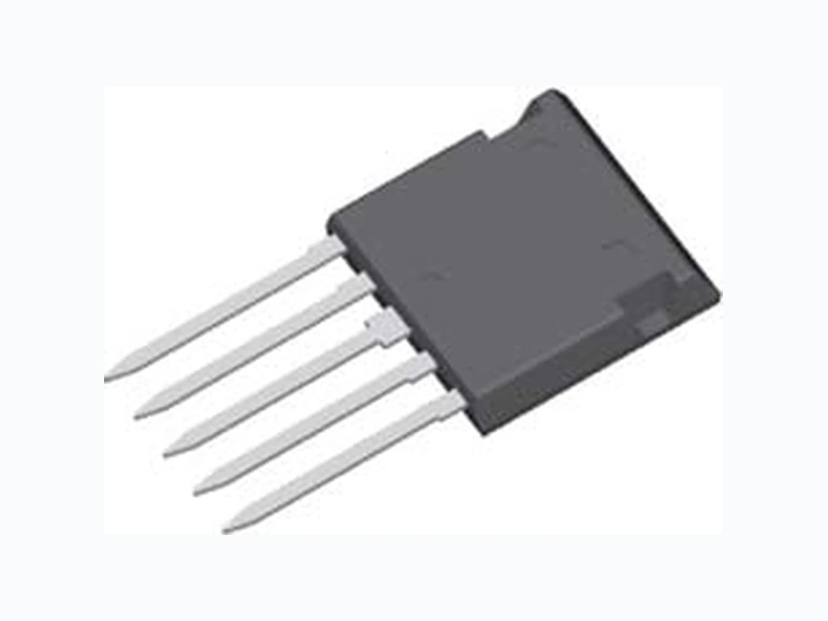
FMM75-01F IXYS
Document overview
- PDF pages: 2
Technical content
Page 1
HiPerFETTM Power MOSFET
Phaseleg Topology in ISOPLUS i4-PACTM
Preliminary data
MOSFET T1/T2
Symbol
Conditions
VDSS
TVJ = 25°C to 150°C
VGS
ID25
TC = 25°C
ID90
TC = 90°C
IF25
(body diode) TC = 25°C
IF90
(body diode) TC = 90°C
VDS < VDSS; IF ≤ 300A;⎮diF/dt⎮≤ 100A/µs; RG = 2 Ω
dv/dt
TVJ = 150°C
EAR
TC = 25°C
FMM 75-01F
ID25
= 75 A
VDSS
= 100 V
RDSon typ. = 18 mΩΩΩΩΩ
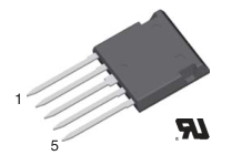
3 T1 5
4 T2 1
2
Features
- HiPerFETTM technology
Maximum Ratings
- low RDSon - low gate charge for high frequency
100 V operation - unclamped inductive switching (UIS)
±20 V capability
75 A - dv/dt ruggedness
50 A - fast intrinsic reverse diode
- ISOPLUS i4-PACTM package
100 A - isolated back surface
60 A - low coupling capacity between pins and heatsink
5 V/ns - enlarged creepage towards heatsink - application friendly pinout
30 mJ - low inductive current path - high reliability - industry standard outline
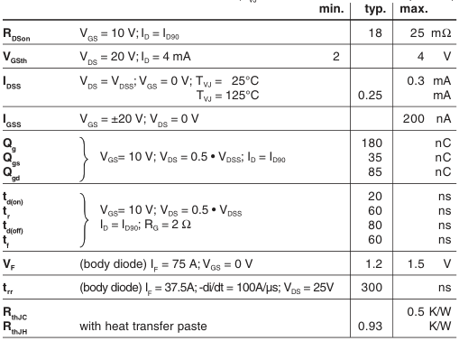
Characteristic Values
Symbol
Conditions
- UL registered E 72873
(TVJ = 25°C, unless otherwise specified)
Applications
- drives and power supplies
- battery or fuel cell powered
- automotive, industrial vehicle etc.
- secondary side of mains power supplies
IXYS reserves the right to change limits, test conditions and dimensions. IXYS reserves the right to change limits, test conditions and dimensions.
1 - 2
© 2004 IXYS All rights reserved
Page 2
Component
Symbol
Conditions
TVJ Tstg
IISOL ≤ 1 mA; 50/60 Hz
VISOL
FC
mounting force with clip
Symbol
Conditions
FMM 75-01F
Maximum Ratings
°C
-55...+175
°C
-55...+125
2500 V~
20...120
N
Characteristic Values
| min. | typ. | max. |
|---|---|---|
| C coupling capacity between shorted p pins and mounting tab in the case | 40 | pF |
| d ,d pin - pin 1.7 S A d ,d pin - backside metal 5.5 S A | mm mm | |
| Weight | 9 | g |
IXYS reserves the right to change limits, test conditions and dimensions.
2 - 2
© 2004 IXYS All rights reserved