
 Download PDF
DATASHEET SEARCH SITE
Document overview
- PDF pages: 2
Technical content
Page 1
Communication BUS Varistor
GENERAL DESCRIPTION
The CAN BUS and FlexRay varistor is a zinc oxide (ZnO) based ceramic semiconductor device
with non- linear voltage-current characteristics (bi-directional) similar to back-to-back Zener
diodes and an EMC capacitor in parallel (see equivalent circuit model). They have the added
advantage of greater current and energy handling capabilities as well as EMI/RFI attenuation.
Devices are fabricated by a ceramic sintering process that yields a structure of conductive ZnO
grains surrounded by electrically insulating barriers, creating varistor like behavior.
HOW TO ORDER
CAN
0001
D
P
Style
Case Size
Packaging Code
Termination
(Reel Size)
P = Ni/Sn Alloy
CAN = CAN BUS 0001 = 0603 Discrete
D = 7" reel (1,000 pcs.)
(Plated)
FLX = FlexRay
0002 = 0405 2-Element
R = 7" reel (4,000 pcs.)
0004 = 0612 4-Element
T = 13" reel (10,000 pcs.)
0005 = 0402 Discrete
W = 7" reel (10,000 pcs.) 0402 and 0201 only
PERFORMANCE CHARACTERISTICS
| AVX Part No. | V (DC) W | V (AC) W | V B | I L | E T | I P | Cap. | Case Size | Elements | |
|---|---|---|---|---|---|---|---|---|---|---|
| CAN0001_ _ | ≤18 | ≤14 | 120 | 2 | 0.015 | 4 | 22 | 0603 | 1 | |
| CAN0002_ _ | ≤18 | ≤14 | 70 | 2 | 0.015 | 4 | 22 | 0405 | 2 | |
| CAN0004_ _ | ≤18 | ≤14 | 100 | 2 | 0.015 | 4 | 22 | 0612 | 4 | |
| CAN0005_ _ | ≤18 | ≤14 | 33 | 2 | 0.015 | 4 | 37 | 0402 | 1 | |
| FLX0005_ _ | ≤18 | ≤14 | 26 | 5 | 0.020 | 4 | 17 | 0402 | 1 | |
| Termination Finish Code | ||||||||||
Packaging Code VW(DC) DC Working Voltage (V) VW(AC) AC Working Voltage (V) VB Typical Breakdown Voltage (V @ 1mADC ) VC Clamping Voltage (V @ IVC) IVC Test Current for VC (A, 8x20μS)
EQUIVALENT CIRCUIT MODEL
Discrete MLV Model
To Device
PCB
Requiring
Trace
Protection
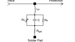
Where: Rv
= Voltage Variable resistance (per VI curve)
≥ 1012 Ω Rp
C = defined by voltage rating and energy level
Ron
= turn on resistance = parallel body inductance
Lp
LEAD-FREE COMPATIBLE
COMPONENT
IL Maximum Leakage Current at the Working Voltage (μA) ET Transient Energy Rating (J, 10x1000μS) IP Peak Current Rating (A, 8x20μS) Cap Maximum Capacitance (pF) @ 1 MHz and 0.5Vrms
Temp Range
-55ºC to +125ºC
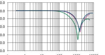
-10.0
-20.0
-30.0
-40.0
-50.0
1 10 100 1000 10000
0
Frequency (MHz)
CAN0001
CAN0005
FLX0005
Typical Pulse Rating Curve
10000
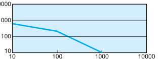
Pulse Duration (µS)
Page 2
Communication BUS Varistor
PHYSICAL DIMENSIONS
mm (inches)
| 0402 Discrete | 0603 Discrete | 0405 Array | 0612 Array | |
| Length | 1.00 ±0.10 (0.040 ±0.004) | 1.60 ±0.15 (0.063 ±0.006) | 1.00 ±0.15 (0.039 ±0.006) | 1.60 ±0.20 (0.063 ±0.008) |
| Width | 0.50 ±0.10 (0.020 ±0.004) | 0.80 ±0.15 (0.032 ±0.006) | 1.37 ±0.15 (0.054 ±0.006) | 3.20 ±0.20 (0.126 ±0.008) |
| Thickness | 0.60 Max. (0.024 Max.) | 0.90 Max. (0.035 Max.) | 0.66 Max. (0.026 Max.) | 1.22 Max. (0.048 Max.) |
| Term Band Width | 0.25 ±0.15 (0.010 ±0.006) | 0.35 ±0.15 (0.014 ±0.006) | 0.36 ±0.10 (0.014 ±0.004) | 0.41 ±0.10 (0.016 ±0.010) |
SOLDER PAD DIMENSIONS
mm (inches)
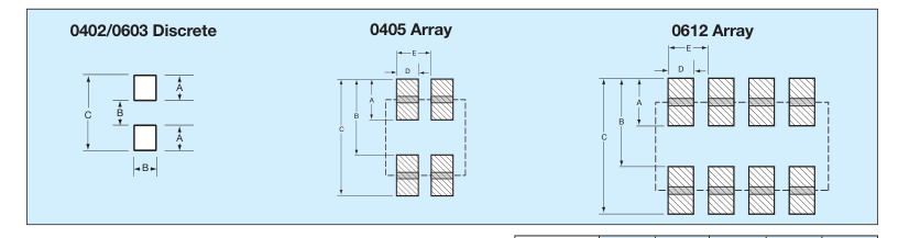
| A | B | C | D | E | |
| 0402 Discrete | 0.61 (0.024) | 0.51 (0.020) | 1.70 (0.067) | – | – |
| 0603 Discrete | 0.89 (0.035) | 0.76 (0.030) | 2.54 (0.100) | – | – |
| 0405 Array | 0.46 (0.018) | 0.74 (0.029) | 0.12 (0047) | 0.38 (0.015) | 0.64 (0.025) |
| 0612 Array | 0.89 (0.035) | 1.65 (0.065) | 2.54 (0.100) | 0.46 (0.018) | 0.76 (0.030) |
APPLICATION
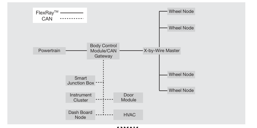
AVX CAN BUS and FlexRay varistors offer significant advantages in general areas of a typical CAN or FlexRay network as shown on the right. Some of the advantages over diodes include:
- space savings
- higher ESD capability @ 25kV contact
- higher in rush current (4A) 8 x 20μS
- FIT rate ≤0.1 failures (per billion hours)
0402, 0603
0405
0612
Discrete
Array
Array