


 Download PDF
DATASHEET SEARCH SITE
Document overview
- PDF pages: 4
Technical content
Page 1
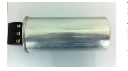
PACKAGING MATERIAL
- Aluminum can with soft PU
STANDARDS
IEC 61071-1, IEC 61071-2: Power electronic capacitors IEC 60831: Shunt power capacitors of selfhealing type for ac systems having a rated voltage up to and including 1kv
HOW TO ORDER
6
V
0335
FLB A
Dielectric
Voltage
Capacitance
Series Case
EIA Code
6 = Polypropylene
A = 230V
A
I = 400V 0103 = 0.01μF
B
L = 440V
C
J = 525V
D
N = 660V
E
O = 690V
F G H J
The FLB series uses metallized polypropylene dielectric, aluminum can, impregnated with soft PU specially treated to have a very high dielectric strength in operating conditions up to 85°C. The FLB has been designed with overpressure disconnected device. They are suitable for power factor correction and output AC filtering for power converters, UPS systems, solar inverters and motor drives etc.
APPLICATIONS
- The FLB capacitor is particularly designed for AC filtering and power factor correction.
HOT SPOT CALCULATION
See Hot Spot Temperature, page 2. θhot spot = θambient + (Pd + Pt) x Rth with Pd (Dielectric losses) = Q x tgδ0 Q x tgδ0 ⇒ [ 1⁄2 x Cn x (Vpeak to peak)2 x f ] x tgδ0 tgδ0 (tan delta) For polypropylene, tgδ0 = 2 x 10⁻⁴ for frequencies up to 1MHz and is independent of temperatures. Pt (Thermal losses) = Rs x (Irms)2 where Cn in Farad Irms in Ampere
f in Hertz
in Ohm
θ in °C
V in Volt
Rs
Rth in °C/W
WORKING TEMPERATURE
According to the power to be dissipated – -40°C to +85°C
LIFETIME EXPECTANCY
One unique feature of this technology (as opposed to aluminum electrolytic) is how the capacitor reacts at the end of its lifetime. Unlike aluminum electrolytic film capacitors do not have a catastrophic failure mode. Film capacitors simply experience a parametric loss of capacitance of about 5% from initial value, with no risk of short circuit. The capacitor continues to be functional even after this 5% decrease.
K
03
Tolerances
Terminal Code
J = ±5% K = ±10%
03 = 3 phase
Page 2
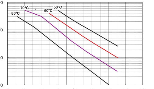
LIFETIME EXPECTANCY VS HOT SPOT TEMPERATURE AND VOLTAGE
Expected Lifetime Curves (FLB Series)
1000000
100000
10000
1000 0.7 0.8 0.9 1 1.1 1.2 1.3 1.4 1.5
Working/Rated Voltage Ratio (Uw/Un)
GENERAL DESCRIPTION
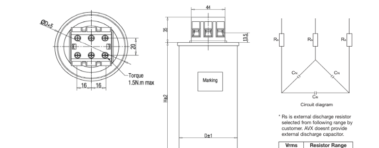

| Vrms | Resistor Range |
| 230V | 220kΩ~400kΩ |
| 400V | 270kΩ~800kΩ |
| 440V | 270kΩ~800kΩ |
| 525V | 270kΩ~1200kΩ |
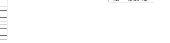
| 660V | 800kΩ~2000kΩ |
| 690V | 800kΩ~1500kΩ |
| AVX Case Ref | OD (mm) | H (mm) |
| A | 85 | 200 |
| B | 85 | 265 |
| C | 85 | 350 |
| D | 116 | 160 |
| E | 116 | 200 |
| F | 116 | 230 |
| G | 116 | 265 |
| H | 136 | 200 |
| J | 136 | 230 |
Page 3
ELECTRICAL CHARACTERISTICS
Climatic category
-40/D (IEC 60068)
Test voltage between terminals @ 25°C 2.15 x Vrms Capacitance range Cn
3\*20.3μF to 3\*335μF
Capacitance Tolerances:
±5%, ±10%
Rated AC Voltage:
Vrms 230V to 690V
Dielectric:
Polypropylene
Lifetime (ΔC/C ≤ 5%):
100,000hrs @ Ur & 70ºC
RATINGS AND PART NUMBER REFERENCE – POLYPROPYLENE DIELECTRIC
| Cap (µF) | Rated Voltage (V) | AVX Part No. | Case Code | Diameter ±2 (mm) | H ±2 (mm) | Output (kvar) | I rms (A) | V/µs (Volt/sec) | I Peak (A) | Packaging Method | |
|---|---|---|---|---|---|---|---|---|---|---|---|
| Vrms = 230V Voltage Code: A | Box Qty (mm) | Dimension | |||||||||
| 3 x 200.6 | 230 | FLBB6A0207K03 | B | 85.0 | 265.0 | 10.0 | 25.1 | 37.0 | 7530 | 8 | 375*285*365 |
| 3 x 200.6 | 230 | FLBD6A0207K03 | D | 116.0 | 160.0 | 10.0 | 25.1 | 37.0 | 7530 | 5 | 375*285*235 |
| 3 x 250.7 | 230 | FLBC6A0257K03 | C | 85.0 | 350.0 | 12.5 | 31.4 | 37.0 | 9420 | 8 | 375*285*435 |
| 3 x 250.7 | 230 | FLBE6A0257K03 | E | 116.0 | 200.0 | 12.5 | 31.4 | 37.0 | 9420 | 5 | 375*285*365 |
| 3 x 300.9 | 230 | FLBC6A0307K03 | C | 85.0 | 350.0 | 15.0 | 37.7 | 37.0 | 11310 | 8 | 375*285*435 |
| 3 x 300.9 | 230 | FLBE6A0307K03 | E | 116.0 | 200.0 | 15.0 | 37.7 | 37.0 | 11310 | 5 | 375*285*365 |
| 3 x 335.0 | 230 | FLBF6A3356K03 | F | 116.0 | 230.0 | 16.7 | 41.9 | 37.0 | 12570 | 5 | 375*285*365 |
| Vrms = 400V Voltage Code: I | |||||||||||
| 3 x 66.3 | 400 | FLBA6I0666K03 | A | 85.0 | 200.0 | 10.0 | 14.4 | 65.0 | 4320 | 8 | 375*285*365 |
| 3 x 82.9 | 400 | FLBA6I0826K03 | A | 85.0 | 200.0 | 12.5 | 18.0 | 65.0 | 5400 | 8 | 375*285*365 |
| 3 x 99.5 | 400 | FLBA6I0996K03 | A | 85.0 | 200.0 | 15.0 | 21.6 | 65.0 | 6480 | 8 | 375*285*365 |
| 3 x 110.7 | 400 | FLBB6I0117K03 | B | 85.0 | 265.0 | 16.7 | 24.1 | 65.0 | 7230 | 8 | 375*285*365 |
| 3 x 110.7 | 400 | FLBD6I0117K03 | D | 116.0 | 160.0 | 16.7 | 24.1 | 65.0 | 7230 | 5 | 375*285*235 |
| 3 x 132.6 | 400 | FLBB6I1326K03 | B | 85.0 | 265.0 | 20.0 | 28.8 | 65.0 | 8640 | 8 | 375*285*365 |
| 3 x 132.6 | 400 | FLBD6I1326K03 | D | 116.0 | 160.0 | 20.0 | 28.8 | 65.0 | 8640 | 5 | 375*285*235 |
| 3 x 165.8 | 400 | FLBB6I1656K03 | B | 85.0 | 265.0 | 25.0 | 36.1 | 65.0 | 10830 | 8 | 375*285*365 |
| 3 x 165.8 | 400 | FLBE6I1656K03 | E | 116.0 | 200.0 | 25.0 | 36.1 | 65.0 | 10830 | 5 | 375*285*365 |
| 3 x 198.9 | 400 | FLBH6I1986K03 | H | 136.0 | 200.0 | 30.0 | 43.3 | 65.0 | 12990 | 4 | 375*285*365 |
| Vrms = 440V Voltage Code: L | |||||||||||
| 3 x 68.5 | 440 | FLBA6L0686K03 | A | 85.0 | 200.0 | 12.5 | 16.4 | 72.0 | 4920 | 8 | 375*285*365 |
| 3 x 77.0 | 440 | FLBA6L0776K03 | A | 85.0 | 200.0 | 14.1 | 18.5 | 72.0 | 5550 | 8 | 375*285*365 |
| 3 x 77.0 | 440 | FLBD6L0776K03 | D | 116.0 | 160.0 | 14.1 | 18.5 | 72.0 | 5550 | 5 | 375*285*235 |
| 3 x 82.2 | 440 | FLBA6L0826K03 | A | 85.0 | 200.0 | 15.0 | 19.7 | 72.0 | 5910 | 8 | 375*285*365 |
| 3 x 92.6 | 440 | FLBA6L0926K03 | A | 85.0 | 200.0 | 16.9 | 22.2 | 72.0 | 6660 | 8 | 375*285*365 |
| 3 x 103.0 | 440 | FLBB6L1036K03 | B | 85.0 | 265.0 | 18.8 | 24.7 | 72.0 | 7410 | 8 | 375*285*365 |
| 3 x 103.0 | 440 | FLBD6L1036K03 | D | 116.0 | 160.0 | 18.8 | 24.7 | 72.0 | 7410 | 5 | 375*285*235 |
| 3 x 109.0 | 440 | FLBB6L1096K03 | B | 85.0 | 265.0 | 20.0 | 26.2 | 72.0 | 7860 | 8 | 375*285*365 |
| 3 x 109.0 | 440 | FLBD6L1096K03 | D | 116.0 | 160.0 | 20.0 | 26.2 | 72.0 | 7860 | 5 | 375*285*235 |
| 3 x 123.3 | 440 | FLBB6L1236K03 | B | 85.0 | 265.0 | 22.5 | 29.5 | 72.0 | 8850 | 8 | 375*285*365 |
| 3 x 123.3 | 440 | FLBD6L1236K03 | D | 116.0 | 160.0 | 22.5 | 29.5 | 72.0 | 8850 | 5 | 375*285*235 |
| 3 x 137.0 | 440 | FLBB6L1376K03 | B | 85.0 | 265.0 | 25.0 | 32.8 | 72.0 | 9840 | 8 | 375*285*365 |
| 3 x 137.0 | 440 | FLBE6L1376K03 | E | 116.0 | 200.0 | 25.0 | 32.8 | 72.0 | 9840 | 5 | 375*285*365 |
| 3 x 154.0 | 440 | FLBB6L1546K03 | B | 85.0 | 265.0 | 28.1 | 36.9 | 72.0 | 11070 | 8 | 375*285*365 |
| 3 x 154.0 | 440 | FLBE6L1546K03 | E | 116.0 | 200.0 | 28.1 | 36.9 | 72.0 | 11070 | 5 | 375*285*365 |
| 3 x 164.4 | 440 | FLBC6L1646K03 | C | 85.0 | 350.0 | 30.0 | 39.4 | 72.0 | 11820 | 8 | 375*285*435 |
| 3 x 164.4 | 440 | FLBE6L1646K03 | E | 116.0 | 200.0 | 30.0 | 39.4 | 72.0 | 11820 | 5 | 375*285*365 |
| 3 x 180.9 | 440 | FLBH6L1806K03 | H | 136.0 | 200.0 | 33.0 | 43.3 | 72.0 | 12990 | 2 | 375*285*365 |
\* Insert K for 10% capacitance tolerance (standard); J (+5%) and M (+20%) tolerances available on request. Values outside this standard range may be available – please contact AVX for any special requirements. AVX reserves the right to supply capacitors to a tighter capacitance tolerance or higher voltage rating, in the same case size.
Page 4
| Cap (µF) | Rated Voltage (V) | AVX Part No. | Case Code | Diameter ±2 (mm) | H ±2 (mm) | Output (kvar) | I rms (A) | V/µs (Volt/sec) | I Peak (A) | Packaging Method | |
|---|---|---|---|---|---|---|---|---|---|---|---|
| Vrms = 525V Voltage Code: J | Box Qty (mm) | Dimension | |||||||||
| 3 x 38.5 | 525 | FLBA6J0386K03 | A | 85.0 | 200.0 | 10 | 11.0 | 86.0 | 3300 | 8 | 375*285*365 |
| 3 x 48.1 | 525 | FLBA6J0486K03 | A | 85.0 | 200.0 | 12.5 | 13.7 | 86.0 | 4110 | 8 | 375*285*365 |
| 3 x 53.1 | 525 | FLBA6J0536K03 | A | 85.0 | 200.0 | 13.8 | 15.2 | 86.0 | 4560 | 8 | 375*285*365 |
| 3 x 57.7 | 525 | FLBA6J0576K03 | A | 85.0 | 200.0 | 15.0 | 16.5 | 86.0 | 4950 | 8 | 375*285*365 |
| 3 x 77.0 | 525 | FLBB6J0776K03 | B | 85.0 | 265.0 | 20.0 | 22.0 | 86.0 | 6600 | 8 | 375*285*365 |
| 3 x 77.0 | 525 | FLBD6J0776K03 | D | 116.0 | 160.0 | 20.0 | 22.0 | 86.0 | 6600 | 5 | 375*285*235 |
| 3 x 96.2 | 525 | FLBB6J0966K03 | B | 85.0 | 265.0 | 25.0 | 27.5 | 86.0 | 8250 | 8 | 375*285*365 |
| 3 x 96.2 | 525 | FLBE6J0966K03 | E | 116.0 | 200.0 | 25.0 | 27.5 | 86.0 | 8250 | 5 | 375*285*365 |
| 3 x 115.4 | 525 | FLBF6J1156K03 | F | 116.0 | 230.0 | 30.0 | 33.0 | 86.0 | 9900 | 5 | 375*285*365 |
| 3 x 115.4 | 525 | FLBH6J1156K03 | H | 136.0 | 200.0 | 30.0 | 33.0 | 86.0 | 9900 | 2 | 375*285*365 |
| 3 x 138.2 | 525 | FLBG6J1386K03 | G | 116.0 | 265.0 | 35.9 | 39.5 | 86.0 | 11850 | 5 | 375*285*365 |
| 3 x 138.2 | 525 | FLBJ6J1386K03 | J | 136.0 | 230.0 | 35.9 | 39.5 | 86.0 | 11850 | 2 | 375*285*365 |
| 3 x 142.8 | 525 | FLBG6J1426K03 | G | 116.0 | 265.0 | 37.1 | 40.8 | 86.0 | 12240 | 5 | 375*285*365 |
| 3 x 142.8 | 525 | FLBJ6J1426K03 | J | 136.0 | 230.0 | 37.1 | 40.8 | 86.0 | 12240 | 2 | 375*285*365 |
| Vrms = 660V Voltage Code: N | |||||||||||
| 3 x 20.3 | 660 | FLBA6N0206K03 | A | 85.0 | 200.0 | 8.33 | 7.3 | 108.0 | 2190 | 8 | 375*285*365 |
| 3 x 24.4 | 660 | FLBa6N0246K03 | A | 85.0 | 200.0 | 10.0 | 8.7 | 108.0 | 2610 | 8 | 375*285*365 |
| 3 x 30.4 | 660 | FLBB6N0306K03 | B | 85.0 | 265.0 | 12.5 | 10.9 | 108.0 | 3270 | 8 | 375*285*365 |
| 3 x 36.5 | 660 | FLBB6N0366K03 | B | 85.0 | 265.0 | 15.0 | 13.1 | 108.0 | 3930 | 8 | 375*285*365 |
| 3 x 40.7 | 660 | FLBB6N0406K03 | B | 85.0 | 265.0 | 16.7 | 14.6 | 108.0 | 4380 | 8 | 375*285*365 |
| 3 x 48.7 | 660 | FLBC6N0486K03 | C | 85.0 | 350.0 | 20.0 | 17.5 | 108.0 | 5250 | 8 | 375*285*435 |
| 3 x 55.8 | 660 | FLBC6N0556K03 | C | 85.0 | 350.0 | 22.9 | 20.0 | 108.0 | 6000 | 8 | 375*285*435 |
| Vrms = 690V Voltage Code: O | |||||||||||
| 3 x 27.9 | 690 | FLBB6O0276K03 | B | 85.0 | 265.0 | 12.5 | 10.5 | 112.0 | 3150 | 8 | 375*285*365 |
| 3 x 33.4 | 690 | FLBB6O0336K03 | B | 85.0 | 265.0 | 15.0 | 12.5 | 112.0 | 3750 | 8 | 375*285*365 |
| 3 x 44.6 | 690 | FLBC6O0446K03 | C | 85.0 | 350.0 | 20.0 | 16.7 | 112.0 | 5010 | 8 | 375*285*435 |
| 3 x 55.7 | 690 | FLBC6O0556K03 | C | 85.0 | 350.0 | 25.0 | 20.9 | 112.0 | 6270 | 8 | 375*285*435 |
\* Insert K for 10% capacitance tolerance (standard); J (+5%) and M (+20%) tolerances available on request. Values outside this standard range may be available – please contact AVX for any special requirements. AVX reserves the right to supply capacitors to a tighter capacitance tolerance or higher voltage rating, in the same case size.