Download PDF
FED20W ASTRODYNE
Document overview
- PDF pages: 3
Technical content
Page 1

FED20W series
Isolated and Regulated 20 WATT Modular DC/DC Converters
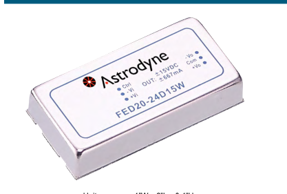
Wide 4 : 1 Input Range
High Efficiency to 89%
Regulated Outputs
1600V Isolation
6 Sided Shielding
Standard Pinouts
Unit measures 1”W x 2”L x 0.4”H
Model Number Output Volts Output Amps Input Range Input Amps (NL/FL) Ripple & Noise Efficiency Capacitive Load
SINGLE OUTPUT
9-36 VDC 50 / 934 mA
FED20-24S3P3W 3.3 VDC
5.5
60mV p-p
85% 18000uF max.
18-75 VDC 35 / 467 mA
FED20-48S3P3W
5.5
60mV p-p
85% 18000uF max.
9-36 VDC 65 / 922 mA
FED20-24S05W 5 VDC
4
75mV p-p
88% 9600uF max.
18-75 VDC 35 / 496 mA
FED20-48S05W
4
75mV p-p
88% 9600uF max.
9-36 VDC 22 / 1018 mA
FED20-24S12W 12 VDC
1.67
75mV p-p
86% 1650uF max.
18-75 VDC 15 / 503 mA
FED20-48S12W
1.67
75mV p-p
87% 1650uF max.
9-36 VDC 22 / 1014 mA
FED20-24S15W 15 VDC
1.33
75mV p-p
86% 1050uF max.
18-75 VDC 15 / 501 mA
FED20-48S15W
1.33
75mV p-p
87% 1050uF max.
DUAL OUTPUT
9-36 VDC 55 / 992 mA
FED20-24D05W ±5 VDC
±2
100mV p-p
88% ±4800uF max.
18-75 VDC 35 / 490 mA
FED20-48D05W
±2
100mV p-p
89% ±4800uF max.
9-36 VDC 30 / 1004 mA
FED20-24D12W ±12 VDC
±0.833
100mV p-p
87% ±825uF max.
18-75 VDC 17 / 496 mA
FED20-48D12W
±0.833
100mV p-p
88% ±825uF max.
9-36 VDC 30 / 1005 mA
FED20-24D15W ±15 VDC
±0.667
100mV p-p
87% ±525uF max.
18-75 VDC 17 / 496 mA
FED20-48D15W
±0.667
100mV p-p
88% ±525uF max
Page 2

FED20W series
Isolated and Regulated 20 WATT Modular DC/DC Converters
INPUT SPECIFICATIONS
I/P Voltage Range (24/48V Nom.) 9-36 / 18-75VDC Voltage Surge (100mS max)
24 V: 50 VDC; 48 V: 100 VDC
Under Voltage Lockout
24 VDC I/P DC/DC ON: 9 VDC OFF: 7.5 VDC 48 VDC I/P DC/DC ON: 15 VDC OFF: 18 VDC
Input Filter
Pi Type
Input Voltage Variation (dv/dt) 5V/rms, max. to ETS300 132 part 4.4 Input Reflected Ripple Current 20mA p-p Start Up Time (Power Up or RC) 20mS, typ. On/Off Control Positive Logic: (Ref to - Input) is standard.
ON = Open or 3V < Vr < 12V OFF = Short or 0V < Vr < 1.2V
Negative Logic: (optional)
ON = Short or 0V < Vr < 1.2V OFF = Open or 3V < Vr < 12V
Efficiency
See Selection Chart
OUTPUT SPECIFICATIONS
Voltage and Current
See Selection Chart
Load Regulation NL-FL
Singles: ±0.5% Duals: ±1%
Cross Regulation (Dual 25%-FL) ±5% Voltage Adjustability (Single O/P) ±10% Line Regulation (Single/Dual) ±0.2% / ±0.5% Temperature Coefficient
±0.02%/°C, max.
Ripple/Noise
See Selection Chart
Voltage Accuracy
± 1%
Transient Response Recovery
25% Load Step Change
250 microSeconds
Short Circuit Protection
Continuous Hiccup, self-recovering
Overvoltage Protection, Zener Diode Clamp:
3.3V Output
3.9Volts
5V Output
6.2Volts
12V Output
15Volts
15V Output
18Volts
Overload Protection
150% of FL Rating, typ.
\* These are stress ratings. Exposure of the devices to any of these conditions may adversely affect long term reliability. Proper operation under conditions other than the standard operating conditions is neither warranteed nor implied.
GENERAL SPECIFICATIONS
Input-Out Isolation
1600VDC
In/Out Capacitance
1500 pF, max.
Isolation Resistance
10000 M Ohms
Switching Frequency
400Khz, typ
ENVIRONMENTAL SPECIFICATIONS
Oper. Temperature
-40 to +105°C (see derate curve)
Relative Humidity
5-95%
Storage Temperature
-55 to +125°C \*
Maximum Case Temp
105°C \*
Thermal Impedance
Convection: 12°C/Watt Convection w. Heatsink: 10°C/Watt
Thermal Shock
MIL-STD-810D
Vibration
10-55Hz 10G 30 min. on X, Y, Z axes
MTBF BELLCORE TR-NWT-000322 Case 1: 50% Stress, Temp. @ 40°C
1.691 MHrs
MIL-HDBK-217F TA=25°C FL, Ground Benign, Controlled Environment
562.9 KHrs
EMI
EN55022A
ESD
EN61000-4-2 Criteria B
Radiated Immunity
EN61000-4-3 Criteria A
EFT
EN61000-4-4B Criteria B
Surge
EN61000-4-5B Criteria B
Conducted Immunity
EN61000-4-6A Criteria A
PHYSICAL SPECIFICATIONS
Case Material
Nickel-Coated Copper w. FR4 Base
Construction
Encapsulated w, UL94-V0 Epoxy
Dimensions
2”L x 1”W x 0.4”H (50.8 x 25.4 x 10.2mm)
Weight
0.95oz (27g)
All specifications are typical at nominal input, full load, and 25DegC unless otherwise noted
Page 3

FED20W series
Isolated and Regulated 20 WATT Modular DC/DC Converters
MECHANICAL DIMENSIONS
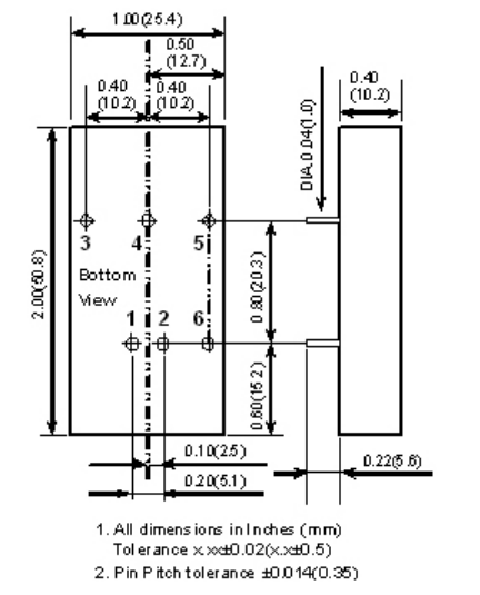
Pin # Single
Dual
1 + Input
+ Input
2 - Input
- Input
3 + Output
+ Output
4 Trim
Common
5 - Output
- Output
6 CTRL
CTRL
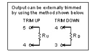
OUTPUT DERATING CURVES