
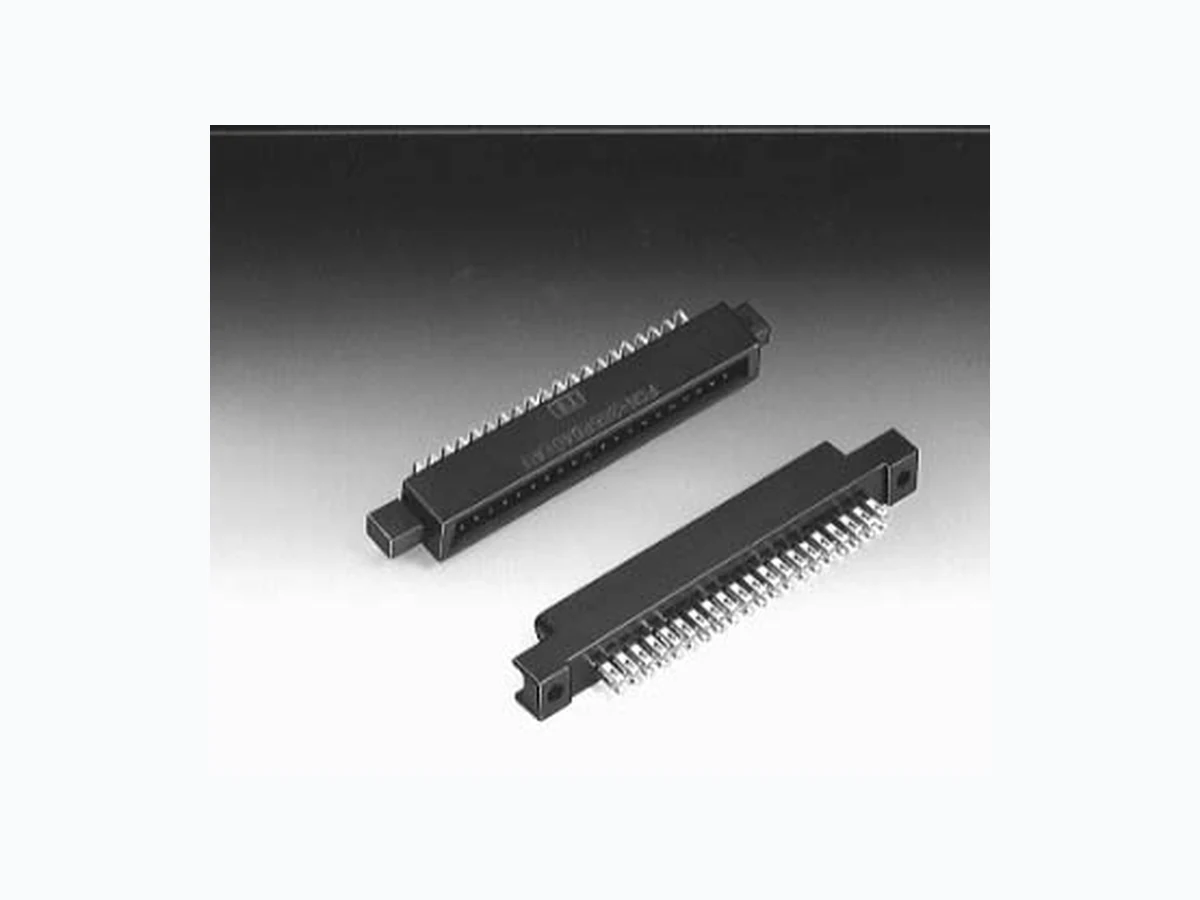
FCN-363T-T011 ETC2
Document overview
- Manufacturer or author: Provided By www.digicamel.com(FREE DATASHEET DOWNLOAD SITE)
- PDF pages: 26
Technical content
- Many applications Various connectors are available for connection by means of soldering, wire wrapping, crimping, PC board mounting, and insulation displacement connection (IDC). The user can choose a plug and jack combination that best meet each application.
- Small size for high-density mounting The connectors are small with a contact and terminal pitch of 2.54 mm (0.100 in.) between pins and between rows and are thus well suited for high-density mounting.
- Sturdy shell guide Sturdy shell guides are used to prevent mismating and to protect the pins.
- Excellent cost performance Streamlined design and automated manufacturing, including use of partial solder plating, provide excellent cost performance. n SPECIFICATIONS n MATERIALS Item Operating temperature range Current Rating Voltage Rating Contact resistance Insulation resistance Dielectric withstanding voltage Insertion force Withdrawal force Applicable wire Applicable PC board Specification –55°C to +85°C DC 3 A (IDC type: 1 A) AC 250 V 15 mΩ max. (DC 6 V, 0.3 A) 1000 MΩ min. (DC 500 V) AC 500 V for 1 minute 2.5 kg max. (8 contacts), 20 kg max. (64 contacts) 0.3 kg min. (8 contacts), 2.3 kg min. (64 contacts) φ0.60 mm (0.024 in.) max, AWG #23 or less Contacts for thick wires φ0.64 mm (0.025 in.) to φ0.32 mm Flat cable 1.27 mm (0.050 in.) pitch, AWG #28 (stranded wire), AWG #30 (solid wire) 1.6 mm (0.063 in.) standard thick Soldering Wire-wrapping Crimping IDC Item Insulator Conductor Plating Material Polyester (363J: PC94V-2) Copper alloy Gold plating, silver plating FUJITSU TAKAMISAWA COMPONENT CATALOG RECTANGULAR CONNECTORS FCN-360 SERIES
With type H/E cover With type E cover With type Ccover
SOLDERING TYPE (PLUG) n DIMENSIONS Unit: mm (in.) n MOUTING HOLE LAYOUT [Panel] Unit: mm (in.) n PART NUMBERS AND DIMENSIONS Number of contacts Part number FCN-361P008-AU FCN-361P016-AU FCN-361P024-AU FCN-361P032-AU FCN-361P040-AU FCN-361P048-AU FCN-361P056-AU FCN-361P064-AU Dimensions: mm (in.) A 28.84 (1.135) 39.0 (1.535) 49.16 (1.935) 59.32 (2.335) 69.48 (2.735) 79.64 (3.135) 89.8 (3.535) 99.96 (3.935) B 23.34 (0.918) 33.5 (1.318) 43.66 (1.718) 53.82 (2.118) 63.98 (2.518) 74.14 (2.918) 84.3 (3.318) 94.46 (3.718) C 17.84 (0.702) 28.0 (1.102) 38.16 (1.502) 48.32 (1.902) 58.48 (2.302) 68.64 (2.702) 78.8 (3.102) 88.96 (3.502) D 7.62 (0.3) 17.78 (0.7) 27.94 (1.1) 38.1 (1.5) 48.26 (1.9) 58.42 (2.3) 68.58 (2.7) 78.74 (3.1) D B A 6 (0.236) 2.54 (0.10) 8.25 (0.324) 2.54 (0.10) 5.8 (0.228) 12.1 (0.476) 5 (0.196) 4 (0.157) 0.7 (0.027) 1.5 (0.059) C φ2.8 (0.110) AB 1 2 ±0.3 ±0.15 (0.005) –0 hole(C + 1) B
SOLDERING TYPE (JACK) n DIMENSIONS Unit: mm (in.) n BOARD MOUTING HOLE LAYOUT [Panel] Unit: mm (in.) n PART NUMBERS AND DIMENSIONS Number of contacts Part number FCN-361J008-AU FCN-361J016-AU FCN-361J024-AU FCN-361J032-AU FCN-361J040-AU FCN-361J048-AU FCN-361J056-AU FCN-361J064-AU Dimensions: mm (in.) A 28.84 (1.135) 39.0 (1.535) 49.16 (1.935) 59.32 (2.335) 69.48 (2.735) 79.64 (3.135) 89.8 (3.535) 99.96 (3.935) B 23.34 (0.918) 33.5 (1.318) 43.66 (1.718) 53.82 (2.118) 63.98 (2.518) 74.14 (2.918) 84.3 (3.318) 94.46 (3.718) C 17.84 (0.702) 28.0 (1.102) 38.16 (1.502) 48.32 (1.902) 58.48 (2.302) 68.64 (2.702) 78.8 (3.102) 88.96 (3.502) D 7.62 (0.3) 17.78 (0.7) 27.94 (1.1) 38.1 (1.5) 48.26 (1.9) 58.42 (2.3) 68.58 (2.7) 78.74 (3.1) D B A 2.54 (0.10) 8.25 (0.324) 2.54 (0.10) 5.8 (0.228) 10.8 (0.425) 5 (0.198) 4 (0.157) 0.7 (0.027) 1.5 (0.059) Cφ2.8 (0.110) AB 0.5 (0.019) 6 (0.236) 6 (0.236) ±0.3 ±0.15 (0.005) –0 hole (C + 1) B
WIRE-WRAP TYPE (PLUG) n DIMENSIONS Unit: mm (in.) n MOUTING HOLE LAYOUT Unit: mm (in.) n PART NUMBERS AND DIMENSIONS Number of contacts Part number FCN-362P008-AU FCN-362P016-AU FCN-362P024-AU FCN-362P032-AU FCN-362P040-AU FCN-362P048-AU FCN-362P056-AU FCN-362P064-AU Dimensions: mm (in.) A 28.84 (1.135) 39.0 (1.535) 49.16 (1.935) 59.32 (2.335) 69.48 (2.735) 79.64 (3.135) 89.8 (3.535) 99.96 (3.935) B 23.34 (0.918) 33.5 (1.318) 43.66 (1.718) 53.82 (2.118) 63.98 (2.518) 74.14 (2.918) 84.3 (3.318) 94.46 (3.718) C 17.84 (0.702) 28.0 (1.102) 38.16 (1.502) 48.32 (1.902) 58.48 (2.302) 68.64 (2.702) 78.8 (3.102) 88.96 (3.502) D 7.62 (0.3) 17.78 (0.7) 27.94 (1.1) 38.1 (1.5) 48.26 (1.9) 58.42 (2.3) 68.58 (2.7) 78.74 (3.1) D B A 2.54 (0.10) 8.25 (0.324) 2.54 (0.10) 4 (0.157) 10.3 (0.405) 10.8 (0.425) Cφ2.8 (0.110) AB 0.71 (0.027) Diagonal length [Board] [Panel] D ±0.2 (0.007) ±0.15 (0.005) –0 hole ±0.3 ±0.15 (0.005) –0 hole (C + 1) B
WIRE-WRAP TYPE (JACK) n DIMENSIONS Unit: mm (in.) n MOUTING HOLE LAYOUT Unit: mm (in.) n PART NUMBERS AND DIMENSIONS Number of contacts Part number FCN-362J008-AU FCN-362J016-AU FCN-362J024-AU FCN-362J032-AU FCN-362J040-AU FCN-362J048-AU FCN-362J056-AU FCN-362J064-AU Dimensions: mm (in.) A 28.84 (1.135) 39.0 (1.535) 49.16 (1.935) 59.32 (2.335) 69.48 (2.735) 79.64 (3.135) 89.8 (3.535) 99.96 (3.935) B 23.34 (0.918) 33.5 (1.318) 43.66 (1.718) 53.82 (2.118) 63.98 (2.518) 74.14 (2.918) 84.3 (3.318) 94.46 (3.718) C 17.84 (0.702) 28.0 (1.102) 38.16 (1.502) 48.32 (1.902) 58.48 (2.302) 68.64 (2.702) 78.8 (3.102) 88.96 (3.502) D 7.62 (0.3) 17.78 (0.7) 27.94 (1.1) 38.1 (1.5) 48.26 (1.9) 58.42 (2.3) 68.58 (2.7) 78.74 (3.1) D B A 2.54 (0.10) 8.25 (0.324) 2.54 (0.10) 5.8 (2.283) 10.8 (0.425) 13.5 (0.531) 4 (0.157) 6 (0.236) 6 (0.236) Cφ2.8 (0.110) AB 0.71 (0.027) Diagonal length [Board] [Panel] D ±0.2 (0.007) ±0.15 (0.005) –0 hole B ±0.3 ±0.15 (0.005) –0 hole (C + 1) B
CRIMP TYPE (JACK HOUSING) n DIMENSIONS Unit: mm (in.) n MOUTING HOLE LAYOUT [Panel] Unit: mm (in.) n PART NUMBERS AND DIMENSIONS Number of contacts Part number FCN-363J008 FCN-363J016 FCN-363J024 FCN-363J032 FCN-363J040 FCN-363J048 FCN-363J056 FCN-363J064 Dimensions: mm (in.) D B A 2.54 (0.10) 8.25 (0.324) 2.54 (0.10) 10.8 (0.425) 4 (0.157) 6 (0.236) 6 (0.236) C 5.8 (2.283) 6 (0.236) Pin 1 in row A Pin 1 in row B B 23.34 (0.918) 33.5 (1.318) 43.66 (1.718) 53.82 (2.118) 63.98 (2.518) 74.14 (2.918) 84.3 (3.318) 94.46 (3.718) C 17.84 (0.702) 28.0 (1.102) 38.16 (1.502) 48.32 (1.902) 58.48 (2.302) 68.64 (2.702) 78.8 (3.102) 88.96 (3.502) D 7.62 (0.3) 17.78 (0.7) 27.94 (1.1) 38.1 (1.5) 48.26 (1.9) 58.42 (2.3) 68.58 (2.7) 78.74 (3.1) A 28.84 (1.135) 39.0 (1.535) 49.16 (1.935) 59.32 (2.335) 69.48 (2.735) 79.64 (3.135) 89.8 (3.535) 99.96 (3.935) ±0.3 ±0.15 (0.005) –0 hole (C + 1) B
(Loose piece) FCN-363J-nn /R (Strip reeled) nn is AG or AU. FCN-363J-nn /S (Loose piece) FCN-363J-nn /T (Strip reeled) nn is AG or AU. CRIMP TYPE (CONTACT) n DIMENSIONS Standard contact (applicable wire: AWG #24 to #28) Thick wire connection contact (applicable wire: AWG #22 to #26) Unit: mm (in.) n PART NUMBERS Type Loose piece Strip reeled Plating Gold plating Gold plating Standard FCN-363J-AU FCN-363J-AU/R Thick wire connection contact FCN-363J-AU/S FCN-363J-AU/T n PART NUMBERS OF CRIMPING TOOLS Part number FCN-363T-T005/H (Hand crimping tool) FCN-M110 (Automatic crimping machine) FCN-A105 (Applicator) FCN-363T-T011/H (Hand crimping tool) FCN-M110 (Automatic crimping machine) FCN-A111 (Applicator) [Hand crimping tool] [Semi-automatic crimping machine, applicator] [Contact withdrawal tool] 10 (0.393) 65 (2.559) FCN-360T-T001/H Wire cross-section area (mm2) 0.20 to 0.24 0.13 to 0.16 0.088 to 0.096 0.30 to 0.40 0.20 to 0.24 0.13 to 0.16 Applicable wire AWG #24 AWG #26 AWG #28 AWG #22 AWG #24 AWG #26 Crimp height Insulator diameter φ1.2 mm (0.047 in.) max φ1.2 mm (0.047 in.) max φ1.2 mm (0.047 in.) max 1.25 mm (0.049 in.) to 1.20 mm (0.047 in.) to 1.15 mm (0.045 in.) to Stripped length 3.0 mm (0.118 in.) to 4.0 mm (0.157 in.) 3.0 mm (0.118 in.) to 4.0 mm (0.157 in.) 3.0 mm (0.118 in.) to 4.0 mm (0.157 in.) 3.0 mm (0.118 in.) to 4.0 mm (0.157 in.) 3.0 mm (0.118 in.) to 4.0 mm (0.157 in.) 3.0 mm (0.118 in.) to 4.0 mm (0.157 in.) 0.85 mm (0.033 in.) to 0.75 mm (0.029 in.) to 0.73 mm (0.028 in.) to φ0.9 mm (0.035 in.) 1.8 mm (0.708 in.) φ0.9 mm (0.035 in.) 1.8 mm (0.708 in.) φ0.9 mm (0.035 in.) 1.8 mm (0.708 in.)
STRAIGHT TYPE (PLUG) n DIMENSIONS Unit: mm (in.) n BOARD MOUTING HOLE LAYOUT Unit: mm (in.) D B A C 8.25 (0.324) 10.3 (0.405) 4 (0.157) 0.71 (0.027) φ2.8 (0.110) 2.54 (0.10) Diagonal length B A1 n PART NUMBERS AND DIMENSIONS Number of contacts Part number FCN-364P008-AU FCN-364P016-AU FCN-364P024-AU FCN-364P032-AU FCN-364P040-AU FCN-364P048-AU FCN-364P056-AU FCN-364P064-AU Dimensions: mm (in.) A 28.84 (1.135) 39.0 (1.535) 49.16 (1.935) 59.32 (2.335) 69.48 (2.735) 79.64 (3.135) 89.8 (3.535) 99.96 (3.935) B 23.34 (0.918) 33.5 (1.318) 43.66 (1.718) 53.82 (2.118) 63.98 (2.518) 74.14 (2.918) 84.3 (3.318) 94.46 (3.718) C 17.84 (0.702) 28.0 (1.102) 38.16 (1.502) 48.32 (1.902) 58.48 (2.302) 68.64 (2.702) 78.8 (3.102) 88.96 (3.502) D 7.62 (0.3) 17.78 (0.7) 27.94 (1.1) 38.1 (1.5) 48.26 (1.9) 58.42 (2.3) 68.58 (2.7) 78.74 (3.1) [Board] D ±0.2 (0.007) ±0.15 (0.005) –0 hole
STRAIGHT TYPE (JACK) n DIMENSIONS Unit: mm (in.) n BOARD MOUTING HOLE LAYOUT Unit: mm (in.) D B A C 8.25 (0.324) 2.54 (0.10) 4.2 (0.165) 10.8 (0.425) 5.8 (0.228) 0.71 (0.027) φ2.8 (0.110) 2.54 (0.10) 6 (0.236) 4 (0.157) 6 (0.236) AB Diagonal length n PART NUMBERS AND DIMENSIONS Number of contacts Part number FCN-364J008-AU FCN-364J016-AU FCN-364J024-AU FCN-364J032-AU FCN-364J040-AU FCN-364J048-AU FCN-364J056-AU FCN-364J064-AU Dimensions: mm (in.) A 28.84 (1.135) 39.0 (1.535) 49.16 (1.935) 59.32 (2.335) 69.48 (2.735) 79.64 (3.135) 89.8 (3.535) 99.96 (3.935) B 23.34 (0.918) 33.5 (1.318) 43.66 (1.718) 53.82 (2.118) 63.98 (2.518) 74.14 (2.918) 84.3 (3.318) 94.46 (3.718) C 17.84 (0.702) 28.0 (1.102) 38.16 (1.502) 48.32 (1.902) 58.48 (2.302) 68.64 (2.702) 78.8 (3.102) 88.96 (3.502) D 7.62 (0.3) 17.78 (0.7) 27.94 (1.1) 38.1 (1.5) 48.26 (1.9) 58.42 (2.3) 68.58 (2.7) 78.74 (3.1) [Board] D ±0.2 (0.007) ±0.15 (0.005) –0 hole
RIGHT-ANGLE TYPE (PLUG) n DIMENSIONS Unit: mm (in.) n MOUTING HOLE LAYOUT n NOTE
- Note on mounting a right-angle plug on a board Mount the connector so that it projects from the board by at least 1.5 mm (0.059 in.). D C A 8.25 (0.324) 7 (0.275) 9.5 (0.374) 4 (0.157) φ2.8 (0.110) 0.71 (0.027) 2.54 (0.10) 2.54 (0.10) 1 (0.039) 3 (0.118) 10 (0.393) B 2.54 (0.10) AB Diagonal length Unit: mm (in.) Metal fitting PCB 1.5 mm (0.059 in.) Plug n PART NUMBERS AND DIMENSIONS Number of contacts Part number FCN-365P008-AU FCN-365P016-AU FCN-365P024-AU FCN-365P032-AU FCN-365P040-AU FCN-365P048-AU FCN-365P056-AU FCN-365P064-AU Dimensions: mm (in.) A 28.84 (1.135) 39.0 (1.535) 49.16 (1.935) 59.32 (2.335) 69.48 (2.735) 79.64 (3.135) 89.8 (3.535) 99.96 (3.935) B 23.34 (0.918) 33.5 (1.318) 43.66 (1.718) 53.82 (2.118) 63.98 (2.518) 74.14 (2.918) 84.3 (3.318) 94.46 (3.718) C 17.84 (0.702) 28.0 (1.102) 38.16 (1.502) 48.32 (1.902) 58.48 (2.302) 68.64 (2.702) 78.8 (3.102) 88.96 (3.502) D 7.62 (0.3) 17.78 (0.7) 27.94 (1.1) 38.1 (1.5) 48.26 (1.9) 58.42 (2.3) 68.58 (2.7) 78.74 (3.1) [Board] D ±0.2 (0.0078) ±0.15 (0.005) –0 hole
48.26 (1.9) 58.48 (2.302) 69.48 (2.735) 8.25 (0.324) 4 (0.157) 7 (0.275) 9.5 (0.374) 4 (0.157) φ2.8 (0.110) 0.71 (0.027) 2.54 (0.10) 2.54 (0.10) 6.08 ( 10 (0.393) 63.98 (2.518) 2.54 (0.10) Diagonal length 14.75 (0.374) 2.54 (0.10) RIGHT-ANGLE TYPE (FOR DUAL STACKED MOUNTING [40 CONTACTS ONLY]) n DIMENSIONS Unit: mm (in.) *Contact area: Gold-plated 9.85 ±0.15 ±0.15 (0. )±0.005 2.54 (0.10)63.98 (2.518 )±0.005 ±0.248.26 (1.9 )±0.007 9 (0.354) 6 (0.236) 3 (0.118) 7.75 10.75 (0.) M2.6 n MOUTING HOLE LAYOUT Unit: mm (in.) n METAL FITTINGS FOR DUAL ROW MOUNTING Unit: mm (in.) n PART NUMBER Right-angle type: N630-3651-T919 Metal fittings: N630-3608-X038 20 mm N630-3651-T919 FCN-360A2 (Two) N630-3608-X038 (Two) FCN-365P040-AU 2-M2.6 × 20 mm
- The reference screw length is 20 mm when 1.6-mm-thick PC board is used.
- Please have these screws ready. n MOUTING
RIGHT-ANGLE TYPE (JACK) n DIMENSIONS Unit: mm (in.) n MOUTING HOLE LAYOUT n PART NUMBERS AND DIMENSIONS Number of contacts Part number FCN-365J008-AU FCN-365J016-AU FCN-365J024-AU FCN-365J032-AU FCN-365J040-AU FCN-365J048-AU FCN-365J056-AU FCN-365J064-AU Dimensions: mm (in.) Unit: mm (in.)
- Note on mounting a right-angle jack on a board Mount the connector so that it projects from the board by at least 5 mm (0.197 in.). D C A 8.25 (0.324) 4 (0.157)5 (0.196) 11 (0.433) 5 (0.196) φ2.8 (0.110) 0.8 (0.031) 2.54 (0.10) 2.54 (0.10) 3 (0.118) 8 (0.314) B 2.54 (0.10) AB Diagonal length 5 (0.196) [Board] Edge of board D ±0.2 (0.007) ±0.15 (0.005) –0 hole A 28.84 (1.135) 39.0 (1.535) 49.16 (1.935) 59.32 (2.335) 69.48 (2.735) 79.64 (3.135) 89.8 (3.535) 99.96 (3.935) B 23.34 (0.918) 33.5 (1.318) 43.66 (1.718) 53.82 (2.118) 63.98 (2.518) 74.14 (2.918) 84.3 (3.318) 94.46 (3.718) C 17.84 (0.702) 28.0 (1.102) 38.16 (1.502) 48.32 (1.902) 58.48 (2.302) 68.64 (2.702) 78.8 (3.102) 88.96 (3.502) D 7.62 (0.3) 17.78 (0.7) 27.94 (1.1) 38.1 (1.5) 48.26 (1.9) 58.42 (2.3) 68.58 (2.7) 78.74 (3.1)
IDC TYPE (JACK) n DIMENSIONS A 8.25 (0.324) 1 mm (0.039 in.) or less 5 (0.196) 3.5 (0.137) 22.5 (0.885) (0.393) Row B Row A 2 (0.078) Wire 1 of the cable is connected. [Cable connection] (0.078) Notes: • When a flat cable is connected as shown on the right, wire 1 of the cable is connected to pin 1 in row A of the connector.
- Another type of connector is also available, for which wire 1 of the cable can be connected to pin 1 in row B. Contact Fujitsu for details. Only the close-end type, however, is available. (Part number: FCN-367J0××-nn nn /B) Unit: mm (in.) n PART NUMBERS AND DIMENSIONS Number of contacts Dimensions: mm (in.) Through-end cover FCN-367J008-AU/H FCN-367J016-AU/H FCN-367J024-AU/H FCN-367J032-AU/H FCN-367J040-AU/H FCN-367J048-AU/H FCN-367J056-AU/H FCN-367J064-AU/H Part number A 2.54 (0.10) B C 2.54 (0.10) 8.25 (0.324) 6 (0.236) 5 (0.196) A 15.7 (0.618) A 31 (1.220) 10 (0.393) φ5 (0.196) M2.6 (0.102) [Lock-screw] [Strain relief] [Closed-end type] [Connector cover with IDC holders] [Connector body] 8.25 (0.324) 5 (0.196) 8.25 (0.324) 6 (0.236) A [Through-end type] 4 (0.157) 8.25 (0.324)5 (0.196) A 28.84 (1.135) 39.0 (1.535) 49.16 (1.935) 59.32 (2.335) 69.48 (2.735) 79.64 (3.135) 89.8 (3.535) 99.96 (3.935) B 23.34 (0.918) 33.5 (1.318) 43.66 (1.718) 53.82 (2.118) 63.98 (2.518) 74.14 (2.918) 84.3 (3.318) 94.46 (3.718) D 7.62 (0.3) 17.78 (0.7) 27.94 (1.1) 38.1 (1.5) 48.26 (1.9) 58.42 (2.3) 68.58 (2.7) 78.74 (3.1)
Special IDC tools are used to assemble FCN-360 series connectors and flat cables. n FEATURES
- The mechanisms are simple, so even novices can use them easily.
- Those who already have Fujitsu-manufactured IDC tools for other series connectors need only purchase the locator plate. The hand press and cable cutter are designed to be used in common with all connectors.
- The assembly of cables and connectors with various numbers of contacts can be done by selective setting of the connector guides to the specified positions.
- The cable cutter has an extremely sharp cutting edge. Notes: • A detailed operation manual and instruction manual for IDC tools are available upon request.
- Should any question arise in using the IDC tools, consult our branch offices or agents in your area. Hand press Cable cutter Locator plate (That for the 790 series is shown in the photograph.) n ORDERING CODES FOR IDC TOOLS Tool name Cable cutter (common) Hand press (common) Locator plate (for 360 series connectors) Part number FCN-707T-T001/H FCN-707T-T101/H FCN-367T-T012/H The hand press and cable cutter can be used for other IDC connectors. COVER n COMBINATIONS BETWEEN COVERS AND CONNECTORS Connector Cover FCN-360C nnnnnn -B FCN-360C nnnnnn -C FCN-360C nnnnnn -D FCN-360C nnnnnn -E FCN-360C064-F FCN-360C040-G1 FCN-360C040-H/E FCN-360C040-J1 Plug Soldering Wire-wrapping CrimpingSoldering Jack 8 16 24 32 40 48 56 64 Number of contacts These covers cannot be used for IDC connectors.
COVER (TYPE B) n DIMENSIONS Unit: mm (in.) n EXPLODED VIEW n PART NUMBERS AND DIMENSIONS Number of contacts Part number FCN-360C008-B FCN-360C016-B FCN-360C024-B FCN-360C032-B FCN-360C040-B FCN-360C048-B FCN-360C056-B FCN-360C064-B Dimensions: mm (in.) B 23.34 (0.918) 33.50 (1.318) 43.66 (1.718) 53.82 (2.118) 63.98 (2.518) 74.14 (2.918) 84.30 (3.318) 94.46 (3.718) F 32.08 (1.262) 42.24 (1.662) 52.40 (2.062) 62.56 (2.462) 72.72 (2.862) 82.88 (3.262) 93.04 (3.662) 103.20 (4.062) G 2.0 (0.078) 6.0 (0.236) 10.0 (0.393) 14.0 (0.551) 18.0 (0.708) H φ 5.7 (0.224) φ 5.7 (0.224) φ 8.0 (0.314) 8.0 (0.314) 8.0 (0.314) 8.0 (0.314) 8.0 (0.314) 8.0 (0.314) Two M2 mm (0.079 in.) thread × 8 mm (0.315 in.) long pan head machine screws (shorter) Four M2 mm (0.079 in.) thread nuts Two washers Case Connector Two lock-screws Two M2 mm (0.079 in.) thread × 10 mm (0.394 in.) long pan head machine screws (longer) Note: The screws, nuts, washers, and lock-screws are attached to the cover. GR H F B 28 (1.102) 37 (1.456) 46 (1.811) 1 (0.039) 14 mm (0.551 in.) max 10.3 (0.405) FUJITSU R: 2.84 mm (0.112 in.) (8 and 16 contacts) R: 4.0 mm (0.157 in.) (24 to 64 contacts)
COVER FOR CABLE TO CABLE CONNECTION (TYPE C) n DIMENSIONS Unit: mm (in.) G R H F 28 (1.102 46 (1.811) (0.039) 14 mm (0.551 in.) max. 10.3 (0.405) FUJITSU Metal fittings Note: This cover can be combined with a cover of type B, D, or E for cable- to-cable connection. n EXPLODED VIEW Two M2 mm (0.079 in.) thread × 8 mm (0.315 in.) long pan head machine screws (shorter) Four M2 mm (0.079 in.) thread nuts Two washers Case Connector Two M2 mm (0.079 in.) thread × 10 mm (0.394 in.) long pan head machine screws (longer) Two screws for mounting metal fittings ConnectorTwo metal fittings n PART NUMBERS AND DIMENSIONS Note: The screws, nuts, washers, and accessory are attached to the cover. Number of contacts Part number FCN-360C008-C FCN-360C016-C FCN-360C024-C FCN-360C032-C FCN-360C040-C FCN-360C048-C FCN-360C056-C FCN-360C064-C Dimensions: mm (in.) R: 2.84 mm (0.112 in.) (8 and 16 contacts) R: 4.0 mm (0.157 in.) (24 and 64 contacts) H φ 5.7 (0.224) φ 5.7 (0.224) φ 8.0 (0.314) 8.0 (0.314) 8.0 (0.314) 8.0 (0.314) 8.0 (0.314) 8.0 (0.314) G 2.0 (0.078) 6.0 (0.236) 10.0 (0.393) 14.0 (0.551) 18.0 (0.708) F 32.08 (1.262) 42.24 (1.662) 52.40 (2.062) 62.56 (2.462) 72.72 (2.862) 82.88 (3.262) 93.04 (3.662) 103.20 (4.062)
Four M2 mm (0.079 in.) thread × 8 mm (0.315 in.) long pan head machine screws (shorter) Four M2 mm (0.079 in.) thread nuts Two cable clamps Case Connector Two lock-screws COVER (WIDE OPENING TYPE) (TYPE D) n DIMENSIONS Unit: mm (in.) n EXPLODED VIEW Note: The screws, nuts, cable clamp, and lock- screws are attached to the cover. ICable clamp 7.5 (0.295) F B 37 (1.456) 14 mm (0.551 in.) max. FUJITSU 10.5 (0.413) 28 (1.102) 46 (1.811) 1 (0.039) 10.3 (0.405) n PART NUMBERS AND DIMENSIONS Number of contacts Part number FCN-360C040-D FCN-360C048-D FCN-360C056-D FCN-360C064-D Dimensions: mm (in.) B 63.98 (2.518) 74.14 (2.918) 84.30 (3.318) 94.46 (3.718) F 72.72 (2.862) 82.88 (3.262) 93.04 (3.662) 103.20 (4.062) I 8.0 (0.314) 12.0 (0.472) 16.0 (0.629) 20.0 (0.789)
COVER (LONG-SCREW TYPE) (TYPE E) n DIMENSIONS Unit: mm (in.) n EXPLODED VIEW n PART NUMBERS AND DIMENSIONS Number of contacts Part number FCN-360C008-E FCN-360C016-E FCN-360C024-E FCN-360C032-E FCN-360C040-E FCN-360C048-E FCN-360C056-E FCN-360C064-E Dimensions: mm (in.) Note: The screws, nuts, washers, and lock-screws are attached to the cover. Two M2 mm (0.079 in.) thread × 8 mm (0.315 in.) long pan head machine screws (shorter) Four M2 mm (0.079 in.) thread nuts Two washers Case Connector Two lock-screws Two M2 mm (0.079 in.) thread × 10 mm (0.394 in.) long pan head machine screws (longer) R: 2.84 mm (0.112 in.) (8 and 16 contacts) R: 4.0 mm (0.157 in.) (24 and 64 contacts) H φ 5.7 (0.224) φ 5.7 (0.224) φ 8.0 (0.314) 8.0 (0.314) 8.0 (0.314) 8.0 (0.314) 8.0 (0.314) 8.0 (0.314) B 23.34 (0.918) 33.50 (1.318) 43.66 (1.718) 53.82 (2.118) 63.98 (2.518) 74.14 (2.918) 84.30 (3.318) 94.46 (3.718) F 32.08 (1.262) 42.24 (1.662) 52.40 (2.062) 62.56 (2.462) 72.72 (2.862) 82.88 (3.262) 93.04 (3.662) 103.20 (4.062) G 2.0 (0.078) 6.0 (0.236) 10.0 (0.393) 14.0 (0.551) 18.0 (0.708) G R H F B 14 mm (0.551 in.) max. FUJITSU 53 (2.086) 28 (1.102) 46 (1.811) 1 (0.039) 10.3 (0.405)
COVER (STRAIGHT CABLE-OUT COVER) (TYPE F) n DIMENSIONS Unit: mm (in.) n EXPLODED VIEW n PART NUMBER FCN-360C064-F Note: The screws, nuts, cable clamps, and lock- screws are attached to the cover. Six M2 mm (0.079 in.) thread × 8 mm (0.315 in.) long pan head machine screws Six M2 mm (0.079 in.) thread nuts Case Connector Two lock-screws Two cable clamps 6 (0.236) 103.2 (4.062) 30.5 (1.200) 28 (1.102) 46 (1.811) 55 (2.165) 1 (0.039) 14 mm (0.551 in.) max. 10.3 (0.405) FUJITSU 10 (0.393) 8 (0.314) 37 (1.456) 94.46 (3.718) 17.5 (10.688) 19.5 (0.767)Section S Detail of section S
COVER (RIGHT ANGLE CABLE-OUT COVER) (TYPE G1) n DIMENSIONS Unit: mm (in.) n EXPLODED VIEW Case Connector long pan head machine screws Two cable clamps Case Slider n LOCKED STATE n METAL FITTINGS Metal fittings FCN-360A11 PC board 1 mm (0.039 in.) min. F 6 (0.236) Note: After connectors are mated, moving the slider locks the connectors. Note: The FCN-360 A11-metal- fittings are used for this cover. n PART NUMBER FCN-360C040-G1 F 17 (0.669) (0.393) 81.48 (3.207) (0.669) (0.748) 6 (0.236) 20 (0.787) 14.65 (0.576) 20 (0.787) ø9 (0.354)
COVER (RIGHT ANGLE CABLEOUT COVER) (TYPE H/E) n DIMENSIONS Unit: mm (in.) n EXPLODED VIEW Material: Zync die cast Plating: Nickel plating 1 (0.039) F 1 (0.039) 43.98 (1.731) 72.48 (2.853) 19 (0.748) 12 (0.472) 10 (0.393) M2.5 (0.039) φ11 (0.433) Cable hole Through-hole n PART NUMBER FCN-360C040-H/E Note: The screws, cable clamp, and lock-screws are attached to the cover. Case Connector Two lock-screws long pan head machine screws Cable clamp long pan head machine screws
COVER (OBTUSE ANGLE CABLE-OUT COVER (40 CONTACTS ONLY)) (TYPE J1) n DIMENSIONS Unit: mm (in.) n EXPLODED VIEW Case Connector Cable clamp Three M2 mm (0.079 in.) thread × 14 mm (0.551 in.) long screws Case long screws Two M2.6 mm (0.102 in.) thread × 12 mm (0.472 in.) long screws Two M2.6 mm (0.102 in.) thread nuts Three M2 mm (0.079 in.) thread nuts n PART NUMBER FCN-360C040-J1 F 63.98 (2.518) 24 (0.944) 20 (0.787) Three screws Two screws Cable hole φ12 (0.472)
LOW PROFILE COVER (OBTUSE ANGLE CABLE -OUT) (TYPE J2) n DIMENSION Unit: mm (in.) n EXPLODED VIEW Case Connector Cable clamp Three M2 mm (0.079 in.) thread × 8 mm (0.315 in.) long screws Case Two M2.6 mm (0.102 in.) thread × 25 mm (0.984 in.) long screws Two M2.6 mm (0.102 in.) thread × 6 mm (0.236 in.) long screws Two M2.6 mm (0.102 in.) thread nuts Three M2 mm (0.079 in.) thread nuts n PART NUMBER FCN-360C024-J2 FCN-360C040-J2 F 46 (1.811) M2 (0.078) M2.6 mm (0.102 in.) thread machine screw with washer 10.3 (0.405) 51.41 (2.024) 29.66 (1.167) 1 (0.039) 24 (0.944) 9.5 (0.374) 30˚ 43.66 (1.718) 6 (MAX) 5 (MIN) View from B F 2225 12.75 20° B 63.98 71.73 B 8.70 17.9 View from BM2.6 mm machine screw with washer M2 (0.078) M2 (0.078) 46 (1.811) M2 (0.078) 10.3 (0.405) Part number: FCN-360C024-J2 (24 contacts) Part number: FCN-360C040-J2 (40 contacts)
[Right-angle mounting metal fitting] M2.6 × 10 Metal fitting Plug or jack PCB Jack with cover or plug with cover Note: The M2.6 mm (0.102 in.) thread × 10 mm (0.394 in.) long machine screw shall be separately prepared. Jack with cover Plug PCB Metal fitting [Straight mounting metal fitting] M2.6 × 8 Note: The M2.6 mm (0.102 in.) thread × 8 mm (0.315 in.) long machine screw shall be separately prepared. [Straight mounting round metal fitting] Metal fitting M2.6 × 8 PCB Plug or jack Jack with cover or plug with cover Note: The M2.6 mm (0.102 in.) thread × 8 mm (0.315 in.) long machine screw shall be separately prepared.n SELECTION OF METAL FITTINGS ACCORDING TO COMBINATION OF CONNECTORS AND COVERS 361P 362P 364P 365P 361J With cover FCN-360A4 FCN-360A1 FCN-360A1 FCN-360A2 Without cover FCN-360A5 FCN-360A6 FCN-360A6 FCN-360A3 362J With cover FCN-360A4 FCN-360A1 FCN-360A1 FCN-360A2 Without cover FCN-360A5 FCN-360A6 FCN-360A6 FCN-360A3 363J With cover FCN-360A4 FCN-360A1 FCN-360A1 FCN-360A2 Without cover FCN-360A5 FCN-360A6 FCN-360A6 FCN-360A3 364J With cover FCN-360A4 FCN-360A1 FCN-360A1 FCN-360A2 Without cover FCN-360A5 FCN-360A6 FCN-360A6 FCN-360A3 367J With cover Without cover FCN-360A5 FCN-360A6 FCN-360A6 FCN-360A3 Cover mounting sideJack Plug Metal fitting mounting side Metal fitting part number 361J 362J 363J 364J 365J 367J 361P With cover FCN-360A4 FCN-360A4 FCN-360A4 FCN-360A4 FCN-360A10 (FCN-360A8) FCN-360A4 Without cover FCN-360A5 FCN-360A5 FCN-360A5 FCN-360A5 FCN-360A9 FCN-360A5 Cover mounting sidePlug Jack 361P With cover Without cover FCN-360A7 FCN-360A7 FCN-360A7 FCN-360A7 FCN-360A9 FCN-360A7 364P With cover Without cover FCN-360A7 FCN-360A7 FCN-360A7 FCN-360A7 FCN-360A9 FCN-360A7 Metal fitting mounting side Metal fitting part number Note: When the jack or plug without a cover (shaded part) is used, have M2.6 × 8 mm machine screws ready inorder to tighten the connector.
Unit: mm (in.) Shape Unit: mm (in.) n SHAPES AND DIMENSIONS OF METAL FITTINGS 1.Straight Mounting Metal Fittings Part number Symbol A FCN-360A1 5.3 (0.208) FCN-360A6 6.3 (0.248) 2.Right-angle Mounting Metal Fittings Part number Symbol B C FCN-360A2 3 (0.118) 9 (0.354) FCN-360A3 4 (0.157) 10 (0.393) Shape Unit: mm (in.) Part number Symbol B C FCN-360A8 5.3 (0.208) 13.3 (0.523) FCN-360A9 6.3 (0.248) 14.3 (0.526) Shape Unit: mm (in.) Part number Symbol FCN-360A10 Unit: mm (in.) Part number Symbol FCN-360A11 Unit: mm (in.) 3.Straight Mounting Round Metal Fittings Part number Symbol D FCN-360A4 7.1(0.279) FCN-360A5 9.9 (0.389) FCN-360A7 8.1 (0.318) A 5.5 (0.216) 8.25 (0.326) M2.6 (0.102) B C 4 (0.157) 5.5 (0.216) (0.275) M2.6 (0.102) B C 4 (0.157) 5.4 (0.212) 7.5 (0.295) M2.6 (0.102) (0.157) 5.3 (0.208) 7.5 (0.295) M2.6 (0.102) M2.6 (0.102) 5.5 (0.216) 4.6 (0.181) 8.1 (0.318) (0.039) 4 (0.157) (0.275) M2.6 (0.102) 5.5 (0.216) (0.236) (0.039) 3 (0.118) D 5.25 (0.206) M2.6 (0.102) (0.236)