
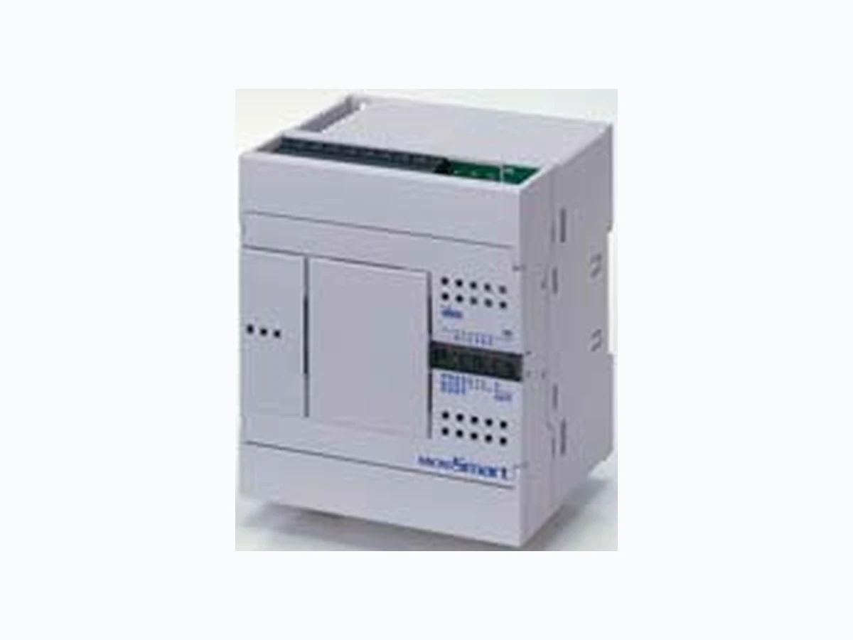
FC4A-J8C1 ETC2
Document overview
- Manufacturer or author: Provided By www.digicamel.com(FREE DATASHEET DOWNLOAD SITE)
- PDF pages: 29
Technical content
PLCsOperator Interfaces Automation Software Power Supplies SensorsCommunication & Networking Programmable Logic Controllers MicroSmart Performance Features: Available in 10, 16, 20, 24, and 40 I/O CPUs. PID Controls -Program up to 14 PID loops High Speed I/O -Built-in 4 high speed inputs -Single or Dual Phase -Max. 20KHz frequency Built-in 2 High speed outputs (Slim model only) Confi gure up to 264 I/O Points Data link up to 32 MicroSmart and Pentra CPUs Using RS485 communication module/port, you can create a network of up to 32 CPUs. Worldwide Approvals -cULus listed, CE marked -Class 1 Div. 2 for hazardous locations -Lloyds Registered and ABS approved for shipping industry MicroSmart CPU Part Numbers All-in-One Appearance Part Number Power I/O Points Input Output Expandability FC4A-C10R2C 24V DC 10 (6 in/ 4 out) 24V DC (Sink/Source) Relay N/A FC4A-C10R2 100-240V AC FC4A-C16R2C 24V DC 16 (9 in/ 7 out) FC4A-C16R2 100-240V AC FC4A-C24R2C 24V DC 24 (14 in/ 10 out)
88 Maximum I/O
(up to 4 expansion modules) FC4A-C24R2 100-240V AC
PLCsOperator Interfaces Automation Software Power Supplies SensorsCommunication & Networking Programmable Logic Controllers MicroSmart CPU Part Numbers Slim Appearance Part Number Power I/O Points Input Output Expandability FC4A-D20RK1 24V DC 20 (12 in/8 out) 24V DC (Sink/Source)
6 Relays, 2 Transistor
244 Maximum I/O
(up to 7 expansion modules) FC4A-D20RS1 6 Relays, 2 Transistor Source FC4A-D20K3 Transistor Sink
148 Maximum I/O
(up to 7 expansion modules) FC4A-D20S3 Transistor Source FC4A-D40K3 40 (24 in/16 out) Transistor Sink
264 Maximum I/O
(up to 7 expansion modules) FC4A-D40S3 Transistor Source
PLCsOperator Interfaces Automation Software Power Supplies SensorsCommunication & Networking Programmable Logic Controllers Digital I/O Expansion Modules Features: 15 modules to choose from Available with Screw or MIL connectors Easy snap-on Available 8, 16 or 32 point modules Up to 512 I/O can be confi gured in the Pentra and 264 I/O in the MicroSmart system Input Modules Appearance Part Number Input Input Points Terminal FC4A-N08A11 100-120V AC Removable Screw Terminals FC4A-N08B1 24V DC FC4A-N16B1 FC4A-N16B3 MIL Connector (ribbon cable) FC4A-N32B3 32
PLCsOperator Interfaces Automation Software Power Supplies SensorsCommunication & Networking Programmable Logic Controllers Digital I/O Expansion Modules Output Modules Appearance Part Number Output Output Points Terminal FC4A-R081 Relay Removable Screw Terminals FC4A-R161 16 FC4A-T08K1 Transistor Sink FC4A-T16K3 16 MIL Connector (ribbon cable) FC4A-T32K3 32
PLCsOperator Interfaces Automation Software Power Supplies SensorsCommunication & Networking Programmable Logic Controllers Digital I/O Expansion Modules Output Modules (cont.) Appearance Part Number Output Output Points Terminal FC4A-T08S1 Transistor Source
8 Removable Screw Terminals
MIL Connector (ribbon cable) FC4A-T32S3 32 Combination I/O Modules Appearance Part Number Input Output I/O Points Terminal FC4A-M08BR1 24V DC (Sink/Source) Relay 8 (4 in/4 out) Removable Screw Terminals FC4A-M24BR2 24 (16 in/ 8 out) Wire Spring Clamp
PLCsOperator Interfaces Automation Software Power Supplies SensorsCommunication & Networking Programmable Logic Controllers Analog I/O Expansion Modules Features: 8 modules 0-10V, 4-20mA, RTD, Thermocouple, Thermistor inputs, 0-10V DC or -10V DC to 10V DC output 12 or 16-bit resolution Fast conversion time Maximum of 56 I/O can be confi gured in the MicroSmart Pentra system Easy to confi gure using a Macro instruction in WindLDR Modules Appearance Part Number I/O Points Input Output Resolution Terminal FC4A-J8C1 8 (8 inputs) 0-10V DC, 4-20mA – 16-bit (0-50000) Removable Screw Terminals FC4A-L03A1 3 (2 inputs, 1 output) 0-10V DC, 4-20mA 12-bit (0-4095) FC4A-J2A1 2 (2 inputs) – FC4A-J4CN1 4 (4 inputs) 0-10V DC, 4-20mA, RTD, Thermocouple – 16-bit (0-50000) FC4A-L03AP1 3 (2 inputs, 1 output) RTD, Thermocouple 0-10V DC, 4-20mA 12-bit (0-4095)
PLCsOperator Interfaces Automation Software Power Supplies SensorsCommunication & Networking Programmable Logic Controllers Appearance Part Number I/O Points Input Output Resolution Terminal FC4A-J8AT1 8 (8 inputs) Thermistor (NTC/PTC) – 12-bit (0-4000) Removable Screw Terminals FC4A-K2C1 2 (2 outputs) – -10 to 10V DC, 4-20mA 16-bit (0-50000) FC4A-K1A1 1 (1 output) – 0-10V DC, 4-20mA 12-bit (0-4095) Analog I/O Expansion Modules Modules (cont.)
PLCsOperator Interfaces Automation Software Power Supplies SensorsCommunication & Networking Programmable Logic Controllers Communication Modules Web Server Module Features: Easy to confi gure Comes with interface cable and Quick Start Guide Part Numbers Appearance Part Number Description FC4A-ENET Web Server Module (includes cable and Quick Start Guide) Quick Start Guide Web Server Module for MicroSmart PLC FC9Y-QS100-0 Quick Start Guide Remote Maintenance Easily monitor machine conditions, change machine confi gurations, or upload and download user programs from anywhere, using IDEC WindLDR software over an Ethernet network. For a more graphical display and remote data archiving, OPC servers, such as IDEC WindSRV or standard SCADA software, can be used. Save time and money: -Access system parameters from your desk, conference room or home to check machine status without walking the factory fl oor. -If a machine is down, you no longer need to send someone with their laptop to debug or download a new user program. Ethernet Web Server Functions Machine status can be monitored and controlled from any PC using stan- dard internet browsers, such as Internet Explorer. A built-in custom template, which allows you to monitor and change system parameters, is included. Get more fl exibility and control by creating your own custom webpage. Alarm Messaging Real-time updates of error status or process conditions can be sent to an email address or cellular phone. A maximum of 32 customizable messages can be pre- defi ned with up to two email addresses each. O/I Connectivity Using the IDEC Web Server Module on an Ethernet network, an IDEC PLC can be confi gured as a host to an IDEC operator interface. This allows the touchscreen and PLC to be in separate locations. No longer hassle with specialized cables and serial connection limitations. Ethernet
PLCsOperator Interfaces Automation Software Power Supplies SensorsCommunication & Networking Programmable Logic Controllers Communication Modules AS-Interface Module AS-Interface Master Module Appearance Part Number Description FC4A-AS62M MicroSmart AS-Interface Master Module The Actuator Sensor-interface (AS-Interface) is the simplest and most cost-ef- fective of the PLC-based , industrial-networking protocols. AS-Interface is a truly open, low-cost electromechanical connection system designed to operate over a two-wire cable carrying data and power over a distance of up to 100m. It is especially suitable for lower levels of plant automation where simple - often binary (On/Off) - fi eld devices such as switches, sensors, and actuators need to interoperate in a local area automation network controlled by a PLC. IDEC sup- ports this open technology. IDEC offers a plug-in AS-Interface master module (as well as other AS-Interface devices, please see AS-Interface Communication section) that is easy to confi g- ure; it can also connect up to 62 slaves. With this technology, you’ll reduce the amount of engineering needed, simplify wiring and enhance your operations; requiring less maintenance. With an average cost of savings of 15 to 40% compared with traditional cabling methods, using an IDEC AS-Interface module is the easy choice. Master-Slave Principle The AS-Interface master controls and monitors the status of slave devices con- nected to the AS-Interface bus. Normally, the AS-Interface master is connected to a PLC (sometimes called ‘host’) or a gateway. Various types of slave devices can be connected to the AS-Interface bus, includ- ing sensors, actuators, and remote I/O devices. Analog slaves can also be con- nected to process analog data. Slaves are available in standard slaves and A/B slaves. Standard slaves have an address of 1 through 31 in the standard address range. A/B slaves have an address of 1A through 31A in the standard address range or 1B through 31B in the expanded address range. Among the A/B slaves, slaves with an address of 1A through 31A are called A slaves, and slaves with an address of 1B through 31B are called B slaves. (see AS-Interface Communication section for more details) Controller Master Master call A-Slaves Master call B-Slaves Slave answer A-Slaves Slave answer B-Slaves Slave 1A Slave 2A Slave 31A Slave 1B Slave 2B Slave 1A Slave 2A Slave 31A Slave 1B Slave 2B
PLCsOperator Interfaces Automation Software Power Supplies SensorsCommunication & Networking Programmable Logic Controllers Optional Modules Appearance Part Number Description Usage FC4A-HPH1 HMI Base Module For mounting HMI module and communication ports with slim model CPU module (HMI module is not included) FC4A-PH1 HMI Module For displaying and changing operands FC4A-PM32 EEPROM memory cartridge 32KB EEPROM memory cartridge FC4A-PM64 EEPROM memory cartridge 64KB EEPROM memory cartridge FC4A-PT1 Clock cartridge Real-time clock cartridge Communication Ports Appearance Part Number Description Terminal FC4A-PC1 RS232C Mini DIN FC4A-PC2 RS485 Mini DIN FC4A-PC3 RS485 Screw Terminal
PLCsOperator Interfaces Automation Software Power Supplies SensorsCommunication & Networking Programmable Logic Controllers Optional Modules Communication Module — for Slim CPU Appearance Part Number Description Terminal FC4A-HPC1 RS232C Mini DIN FC4A-HPC2 RS485 Mini DIN FC4A-HPC3 RS485 Screw Terminal Expansion Power Supply Module Appearance Part Number Description FC5A-EXM1M Master Expansion Power Supply For MicroSmart Pentra FC5A-EXM1S Slave Expansion Power Supply For MicroSmart Pentra FC5A-EXM2 Expansion Power Supply For MicroSmart Pentra Expansion Power Supply System Confi guration FC5A-EXM2 (Expansion Interface Module) Slim CPU Module FC5A-EXM2 FC5A-EXM1M and FC5A-EXM1S (Expansion Interface Master & Salve Modules) Slim CPU Module FC5A-EXM1M FC5A-EXM1S FC5A-KX1C (Expansion Interface Cable)
PLCsOperator Interfaces Automation Software Power Supplies SensorsCommunication & Networking Programmable Logic Controllers Cables Communication Cables Appearance Part Number Length Expanded
Description
FC4A-KC4CA 5ft. (1.53m) Programming cable (Maintenance/User Communication Mode selectable) FC4A-USB 6ft. (1.83m) USB to Serial Con- verter (for use with PC without serial port) FC4A-KC3C 0.33ft. (100mm) Web Server Module interface cable Appearance Part Number Length Expanded FC2A-KM1C 9.84 Ft. (3m) Modem cable. Used to connect a modem to the MicroSmart RS232C port. FC2A-KP1C 9.84 Ft. (3m) User communica- tion cable. Used to connect RS232C equipment to the MicroSmart RS232C port. FC5A-KX1C 3.28 Ft. (1m) MicroSmart Pentra expansion power supply interface cable. Used to connect expansion interface master and expansion slave modules. MIL Connector Cables (use with Breakout Modules) Use with Part Number Model Length Use with Part Number Model Length CPU Module (26-wire) BX1D-S26A, BX1D-T26A FC9Z-H050B26 Non-shielded 1.64ft. (0.5m) I/O Expansion Modules (20-wire) BX1D-S20A, BX1D-T20A FC9Z-H050B20 Non-shielded 1.64ft. (0.5m) FC9Z-H100B26 3.28ft. (1m) FC9Z-H100B20 3.28ft. (1m) FC9Z-H200B26 6.56ft (2m) FC9Z-H200B20 6.56ft (2m) FC9Z-H300B26 9.85ft. (3m) FC9Z-H300B20 9.85ft. (3m) FC9Z-H050A26 Shielded 1.64ft. (0.5m) FC9Z-H050A20 Shielded 1.64ft. (0.5m) FC9Z-H100A26 3.28ft. (1m) FC9Z-H100A20 3.28ft. (1m) FC9Z-H200A26 6.56ft (2m) FC9Z-H200A20 6.56ft (2m) FC9Z-H300A26 9.85ft. (3m) FC9Z-H300A20 9.85ft. (3m) FC9Z-H100C26A Shielded Single Connectors 5ft. (1.5m) FC9Z-H100C20A Shielded Single Connectors 5ft. (1.5m) Breakout Modules Use with Part Number Descrption 26-wire MIL connector cable BX1D-S26A 26-terminal breakout module BX1D-T26A 26-terminal touch-down terminal breakout module 20-wire MIL connector cable BX1D-S20A 20-terminal breakout module BX1D-T20A 20-terminal touch-down terminal breakout module
PLCsOperator Interfaces Automation Software Power Supplies SensorsCommunication & Networking Programmable Logic Controllers Accessories Part Number Use with Description FC4A-PMT13P CPU module 13-position left-side terminal block for FC4A-D20RK1/-D20RS1 CPU FC5A-PMT13P 13-position left-side terminal block for FC5A-D16RK1/-D16RS1 CPU FC4A-PMTS16P 16-position right-side terminal block for FC4A-D20RS1 and FC5A-D16RS1 CPU FC4A-PMTK16P 16-position right-side terminal block for FC4A-D20RK1 and FC5A-D16RK1 CPU FC4A-PMT11P I/O expansion modules 11-position terminal block for 8-pt I/O expansion modules FC4A-PMT10P 10-position terminal block for 16-pt I/O expansion modules FC4A-PMC20P 20-position connector socket for MIL connector I/O expansion modules FC4A-PMC26P 26-position connector socket for MIL connector CPU modules FC4A-PSP1P Direct mounting strips for mounting on a panel FC4A-PMAC2P Analog voltage input cable for slim CPU FC4A-DS824-SW14 14-pt input simulator switch for 24 I/O CPU FC4A-DS824-SW9 9-pt input simulator switch for 16 I/O CPU FC4A-DS824-SW6 6-pt input simulator switch for 10 I/O CPU BNL6 End clips BNDN1000 DIN Rail (1m/3.28’ long, 10.5mm height) BAA1000 DIN Rail (1m/3.28’ long, 7.5mm height) FC9Z-SD2 2.5mm fl athead IDEC screwdriver FC9Y-B812-0A MicroSmart user manual FC9Y-B927-0 MicroSmart Pentra user manual FC9Y-B919 Web Server Module user manual FC9Y-B969-0 FC5A-SIF2 Communication Module user manual FC9Y-B902-0 Analog I/O user manual FC9Y-LP2CDW WindLDR PLC programming software
PLCsOperator Interfaces Automation Software Power Supplies SensorsCommunication & Networking Programmable Logic Controllers Specifi cations All-in-One Part Number AC Power FC5A-C10R2 FC5A-C16R2 FC5A-C24R2 FC4A-C10R2 FC4A-C16R2 FC4A-C24R2 DC Power FC5A-C10R2C FC5A-C16R2C FC5A-C24R2C FC4A-C10R2C FC4A-C16R2C FC4A-C24R2C Rated Voltage AC power model: 100 to 240V AC, DC power model: 24V DC Allowable Voltage Range AC power model: 85 to 264V AC, DC power model: 20.4 to 28.8V DC (including ripple) Rated Power Frequency AC power model: 50/60 Hz (47 to 63 Hz) Maximum Input Current 250mA (85V AC) 160mA (24V DC) 300mA (85V AC) 190mA (24V DC) 450mA (85V AC) 1 360mA (24V DC) 2 250mA (85V AC) 160mA (24V DC) 300mA (85V AC) 190mA (24V DC) 450mA (85V AC) 2 360mA (24V DC) 3 Maximum Power Consumption AC Power FC5A-C10R2/FC4A-C10R2: 30VA (264V AC) / 20VA (100V AC) 3 FC5A-C16R2/FC4A-C16R2: 31VA (264 V AC) / 22VA (100V AC ) 3 FC5A-C24R2/FC4A-C24R2: 40VA (264V AC) / 33VA (100V AC) 1 DC Power FC5A-C10R2C/FC4A-C10R2C: 3.9W (24V DC) 4 FC5A-C16R2C/FC4A-C16R2C: 4.6W (24V DC) 4 FC5A-C24R2C/FC4A-C24R2C: 8.7W (24V DC) 2 Allowable Momentary Power Interruption 10ms (rated power voltage) Dielectric Strength Between power and or terminals: 1500V AC, 1 minute Between I/O and or terminals: 1500V AC, 1 minute Insulation Resistance Between power and or terminals: 10 MΩ minimum (500V DC megger) Between I/O and or terminals: 10 MΩ minimum (500V DC megger) Noise Resistance AC power terminals: 1.5 kV, 50 ns to 1μs DC power terminals: 1.0 kV, 50 ns to 1μs I/O terminals (coupling clamp): 1.5 kV, 50 ns to 1μs Inrush Current 35A 40A 35A 40A Power Supply Wire UL1015 AWG22, UL1007 AWG18 Operating Temperature 0 to 55ºC Storage Temperature –25 to +70ºC (no freezing) Relative Humidity Level RH1 (IEC61131-2), 1 to 95% RH (no condensation) Altitude Operation: 0 to 2,000m, Transport: 0 to 3,000m Pollution Degree 2 (IEC60664-1) Corrosion Immunity Free from corrosive gases Degree of Protection IP20 (IEC60529) Grounding Wire UL1007, AWG16 Vibration Resistance When mounted on a DIN rail or panel surface: 5 to 9 Hz amplitude 3.5 mm, 9 to 150 Hz acceleration 9.8 m/s (1G), 2 hours per axis on each of three mutually perpendicular axes (IEC61131-2) Shock Resistance 147 m/s (15G), 11ms duration, 3 shocks per axis, on three mutually perpendicular axes (IEC61131) Weight AC: 230g DC: 240g AC: 250g DC: 260g AC: 305g DC: 310g AC: 230g DC: 240g AC: 250g DC: 260g AC: 305g DC: 310g 1. CPU module (including 250mA sensor power) + 4 I/O modules 2. CPU module + 4 I/O modules 3. CPU module (including 250mA sensor power) 4. CPU module (24V DC)
PLCsOperator Interfaces Automation Software Power Supplies SensorsCommunication & Networking Programmable Logic Controllers Slim Part Number FC5A-D16RK1 FC5A-D16RS1 FC5A-D32K3 FC5A-D32S3 FC4A-D20K3 FC4A-D20S3 FC4A-D20RK1 FC4A-D20RS1 FC4A-D40K3 FC4A-D40S3 Control System Stored program system Instruction Words 35 basic 88 advanced 92 advanced 55 advanced 72 advanced Program Capacity 1 62.4 KB (10,400 steps) 27 KB (4,500 steps) 31.2 KB (5,200 steps) 2 User Program Storage EEPROM (10,000 times rewritable) Processing Time Basic Instruction 83μs (1,000 steps) 1.65ms (1,000 steps) END Processing 3 0.35ms 0.64ms Expandable I/O Modules 7 modules + additional 8 modules using the expansion power supply module 7 modules I/O Points Input 8 Expansion: 224 Additional: 256
16 Expansion: 224
Additional: 256
12 Expansion: 128 12 Expansion: 224 24 Expansion: 224Output 8 16 8 8 16
Internal Relay 2,048 points 1,024 points Shift Register 256 points 128 points Data Register 42,000 points 4 1,300 points Expansion Data Register 6,000 points — 6,000 points Counter 256 points 100 points Timer (1-sec, 100-ms, 10-ms, 1-ms) 256 points 100 points RAM Backup Backup Data Internal relay, shift register, counter, data register, expansion data register Backup Duration Approx. 30 days (typical) at 25ºC after backup battery fully charged Battery Lithium secondary battery Charging Time Approx. 15 hours for charging from 0% to 90% of full charge Battery Life 5 years Replaceability N/A Self-diagnostic Function Power failure, watchdog timer, data link connection, user program EPPROM sum check, timer/counter preset value sum check, user program RAM sum check, keep data, user program syntax, user program writing, CPU module, clock IC, I/O bus initialize, user program execution Input Filter Without fi lter or 3 to 15ms fi lter (selectable in increments of 1ms) Catch Input/Interrupt Input Four inputs (I2 through I5) Minimum turn on pulse width: 5μs minimum Minimum turn off pulse width: 5μs minimum Four inputs (I2 through I5) Minimum turn on pulse width: 40μs minimum Minimum turn off pulse width: 150μs minimum High- speed Counter Maximum Counting Frequency and High-speed Counter Points Total 4 points Single/two-phase selectable: 100 KHz (2 points) Single-phase:100 KHz (2 points) Total 4 points Single/two-phase selectable: 20 KHz (2 points) Single-phase: 5 KHz (2 points) Counting Range 0 to 4294967295 (32 bits) 0 to 65535 (16 bits) Operation Mode Rotary encoder mode and adding counter mode Analog Potentiometer Number 1 point Data Range 0 to 255 Analog Voltage Input Number 1 point Input Voltage Range 0 to 10V DC Input Impedance Approx. 100kΩ Data Range 0 to 255 (8 bits) Pulse Output Number 2 points 3 points 2 points Maximum Frequency 100KHz 20KHz Sensor Power Supply Output Voltage Current — Overload Detection Isolation Port 1 RS232C (maintenance communication, user communications) Port 2 Communication Adapter (option) 5 Possible Possible Possible Possible Possible Clock Cartridge (option) Possible Possible Possible Possible Possible Memory Cartridge (option) Possible Possible Possible Possible Possible HMI Module (option) Possible Possible Possible Possible Possible 1. 1 step equals 6 bytes. 2. Expandable up to 64 KB when a memory cartridge is used. 3. Not including expansion I/O service time, clock function processing time, data link processing time, and interrupt processing time. 4. Extra data registers D10000 through D49999 are enabled using WindLDR Function Area Settings, then run-time program download cannot be used. 5. Maintenance communication, user communication, Modem communica- tion, data link, Modbus master/slave communication (FC5A only). Note: The maximum number of relay outputs that can be turned on simulat- neously is 54 including those on the CPU module.
PLCsOperator Interfaces Automation Software Power Supplies SensorsCommunication & Networking Programmable Logic Controllers All-in-One Part Number FC5A-C10R2 FC5A-C10R2C FC5A-C16R2 FC5A-C16R2C FC5A-C24R2 FC5A-C24R2C FC4A-C10R2 FC4A-C10R2C FC4A-C16R2 FC4A-C16R2C FC4A-C24R2 FC4A-C24R2C Control System Stored program system Instruction Words 35 basic 76 advanced 76 advanced 81 advanced 38 advanced 40 advanced 46 advanced Program Capacity 1 13.8 KB (2,300 steps) 27 KB (4,500 steps) 54 KB (9,000 steps) 4.8 KB (800 steps) 15 KB (2,500 steps) 27 KB (4,500 steps) User Program Storage EEPROM (10,000 times rewritable) Processing Time Basic Instruction 1.16ms (1,000 steps) 1.65ms (1,000 steps) END Processing 2 0.64ms 0.64ms Expandable I/O Module — 4 modules — 4 modules I/O Points Input 6 9 14 Expansion: 691 4 Expan- sion: 64Output 4 7 10 4 7 10 Internal Relay 2,048 points 256 points 1,024 points Shift Register 128 points 64 points 128 points Data Register 2,000 points 400 points 1,300 points Extra Data Register —— Counter 256 points 32 points 100 points Timer (1-sec, 100-ms, 10-ms, 1-ms) 256 points 32 points 100 points RAM Backup Backup Data Internal relay, shift register, counter, data register Backup Duration Approx. 30 days (typical) at 25ºC after backup battery fully charged Battery Lithium secondary battery Charging Time Approx. 15 hours for charging from 0% to 90% of full charge Battery Life 5 years Replaceability N/A Self-diagnostic Function Power failure, watchdog timer, data link connection, user program EPPROM sum check, timer/counter preset value sum check, user program RAM sum check, keep data, user program syntax, user program writing, CPU module, clock IC, I/O bus initialize, user program execution Input Filter Without fi lter or 3 to 15ms fi lter (selectable in increments of 1ms) Catch Input/Interrupt Input Four inputs (I2 through I5) Minimum turn on pulse width: 40μs minimum Minimum turn off pulse width: 150μs minimum High-speed Counter Maximum Counting Frequency and High-speed Counter Points Total 4 points Single/two-phase selectable: 50KHz (1 point) Single-phase: 5KHz (3 points) Total 4 points Single/two-phase selectable: 20KHz (1 point) Single-phase: 5KHz (3 points) Counting Range 0 to 65535 (16 bits) Operation Mode Rotary encoder mode and adding counter mode Analog Potentiometer Number 1 point 2 points 1 point 2 points Data Range 0 to 255 Analog Voltage Input Number —Input Voltage Range Input Impedance Data Range Pulse Output Number —Max. Frequency Sensor Power Supply (AC Power Only) Output Voltage Current 24V DC (+10% to -15%), 250mA Overload Detection N/A Isolation Isolated from the internal circuit Port 1 RS232C (maintenance communication, user communication) Port 2 Communication Adapter (option) 3 Possible Possible Possible — Possible Possible Clock Cartridge (option) Possible Possible Possible Possible Possible Possible Memory Cartridge (option) Possible Possible Possible Possible Possible Possible HMI Module (option) Possible Possible Possible Possible Possible Possible 1. 1 step equals 6 bytes. 2. Not including expansion I/O service time, clock function processing time, data link processing time, and interrupt processing time. 3. Maintenance communication, user communication, Modem communication, datalink, Modbus master/slave communication (FC5A only). Note: The maximum number of relay outputs that can be turned on simultaneously is 33 including those on the CPU module.
PLCsOperator Interfaces Automation Software Power Supplies SensorsCommunication & Networking Programmable Logic Controllers Communication Port (RS232C Port 1) Model Slim CPU All-in-One CPU Standards EIA RS232C Maximum Baud Rate FC5A: 57,600 bps (maintenance communication) FC4A: 19,200 bps (maintenance communication) Maintenance Communication Possible User Communication Possible Modem Communication N/A Data Link N/A Cable Special cable (FC2A-KC4C, FC2A-KP1C, FC4A-KC1C, FC4A-KC2C) Isolation between Internal Circuit and Communication Port Not isolated Input Specifi cations Part Number – FC5A-D16RK1 FC5A-D16RS1 – FC5A-D32K3 FC5A-D32S3 – FC5A-C10R2 FC5A-C10R2C FC5A-C16R2 FC5A-C16R2C FC5A-C24R2 FC5A-C24R2C FC4A-D20K3 FC4A-D20S3 – FC4A-D20RK1 FC4A-D20RS1 – FC4A-D40K3 FC4A-D40S3 FC4A-C10R2 FC4A-C10R2C FC4A-C16R2 FC4A-C16R2C FC4A-C24R2 FC4A-C24R2C Input Points 12 (12/1 common) (8/1 common) (12/1 common) (8/1 common) (12/1 common) (6/1 common) (9/1 common) (14/1 common) Input Voltage 24V DC sink/source input signal Input Voltage Range 20.4 to 26.4V DC 20.4 to 28.8V DC Input Current FC5A I0, I1, I3, I4, I6, I7: 4.5mA/point (24V DC) I2, I5, I10 to I17: 7mA/point (24V DC) FC4A I0, I1, I6, I7: 5mA/point (24V DC) I2 to I5, I10 to I27: 7mA/point (24V DC) FC5A I0 and I1: 6.4mA/point I2 to I7, I10 to I15: 7mA/point (24V DC) FC4A I0 and I1: 11mA I2 to I7, I10 to I15: 7mA/point (24V DC) Input Impedance FC5A I0, I1, I3, I4, I6, I7: 4.9kΩ I2 to I5, I10 to I17: 3.4kΩ FC4A I0, I1, I6, I7: 5.7kΩ I2 to I5, I10 to I17: 3.4kΩ FC5A I0 and I1: 3.7kΩ I2 to I7, I10 to I15: 3.4kΩ FC4A I0 and I1: 2.1kΩ I2 to I7, I10 to I15: 3.4kΩ Turn ON Time FC5A I0, I1, I3, I4, I6, I7: 5μs + fi lter value I2 and I5: 35μs + fi lter value I10 to I17: 40μs + fi lter value FC4A I0, I1, I6, I7: 35μs + fi lter value I2 to I5: 35μs + fi lter value I10 to I27: 40μs + fi lter value FC5A I0 and I1: 2μs + fi lter value I2 to I7: 35μs + fi lter value I6, I7, I10 to I15: 40μs + fi lter value FC4A I0 and I1: 35μs + fi lter value I2 to I5: 35μs + fi lter value I6, I7, I10 to I15: 40μs + fi lter value Turn OFF Time FC5A I0, I1, I3, I4, I6, I7: 5μs + fi lter value I2 and I5: 150μs + fi lter value I10 to I17: 150μs + fi lter value FC4A I0, I1, I6, I7: 45μs + fi lter value I2 to I5: 150μs + fi lter value I10 to I27: 150μs + fi lter value FC5A I0 and I1: 16μs + fi lter value I2 to I7: 150μs + fi lter value I6, I7, I10 to I15: 150μs + fi lter value FC4A I0 and I1: 45μs + fi lter value I2 to I5: 150μs + fi lter value I6, I7, I10 to I15: 150μs + fi lter value Connector On Mother Board FL26A2MA (Oki Electric Cable) MC1.5/18-G-3.81BK (Phoenix Contact) FL26A2MA (Oki Electric Cable) — Insertion Durability 100 times minimum — Isolation Between input terminals: Photocoupler isolated Internal circuit: Not isolated Input Type 1 (IEC61131-2) External Load for I/O Interconnection Not needed Single Determination Method Static Effect of Improper Input Connection Both sinking and sourcing input signals can be connected. If any input exceeding the rated value is applied, permanent damage may be caused. Cable Length 3 m in compliance with electromagnetic immunity
PLCsOperator Interfaces Automation Software Power Supplies SensorsCommunication & Networking Programmable Logic Controllers Transistor Sink and Source Output Part Number — FC5A-D16RK1 FC5A-D16RS1 FC5A-D32K3 FC5A-D32S3 FC4A-D20RK1 FC4A-D20RS1 — FC4A-D40K3 FC4A-D40S3 Output Points 2 (2/1 com- mon) 2 (2/1 com- mon) 16 (8/1 com- mon) Output Transistor Sink FC5A-D16K1/D32K3 FC4A-D20K3/D20RK1/D40K3 Transistor Source FC5A-D16RS1/D32S3 FC4A-D20S3/D20RS1/D40S3 Load Voltage 24V DC Operating Load Voltage Range 20.4 to 28.8V DC Load Current 0.3A per output point Maximum Load Current 1A per common Voltage Drop (ON Voltage) 1V maximum (voltage between COM and output terminals when output is on) Inrush Current 1A Leakage Current 0.1mA maximum Clamping Voltage 39V±1V Maximum Lamp Load 8W Inductive Load L/R = 10ms (28.8V DC, 1 Hz) External Current Draw Sink output: 100mA maximum, 24V DC (power voltage at the +V terminal) Source output: 100mA maximum, 24V DC (power voltage at the –V terminal) Isolation Between output terminal and internal circuit: Photocoupler isolated Between output terminals: Not isolated Connector on Mother Board FL26A2MA (Oki Electric Cable) MC1.5/16-G- 3.81BK (Phoenix Contact) FL26A2MA (Oki Electric Cable) Connector Insertion/ Removal Durability 100 times minimum Output Delay Turn ON Time FC5A Q0 to Q2: 5μs max. Q3 to Q7, Q10 to Q17: 300μs max. FC4A Q0, Q1: 5μs max. Q2 to Q7, Q10 to Q17: 300μs max. Turn OFF Time FC5A Q0 to Q2: 5μs max. Q3 to Q7, Q10 to Q17: 300μs max. FC4A Q0, Q1: 5μs max. Q2 to Q7, Q10 to Q17: 300μs max. Relay Output Part Number FC5A-C10R2 FC5A-C10R2C FC5A-C16R2 FC5A-C16R2C FC5A-C24R2 FC5A-C24R2C FC5A-D16RK1 FC5A-D16RS1 FC4A-C10R2 FC4A-C10R2C FC4A-C16R2 FC4A-C16R2C FC4A-C24R2 FC4A-C24R2C FC4A-D20RK1 FC4A-D20RS1 No. of Outputs 4 7 10 8 Output Points per Common Line COM0 3 4 4 (Transistor output) COM1 1 2 4 3 COM2 — 1 1 2 COM3 — — 1 1 Output 1 NO form A Maximum Load Current 2A per point 8A per common line Minimum Switching Load 0.1mA/0.1V DC (reference value) Initial Contact Resistance 30 mΩ maximum Electrical Life 100,000 operations minimum (rated load 1,800 operations/hour) Mechanical Life 20,000,000 operations minimum (no load 18,000 operations/hour) Rated Load 240V AC/2A (resistive load, inductive load cos ø = 0.4) 30V DC/2A (resistive load, inductive load L/R =7ms) Dielectric Strength Between output and terminals: 1,500V AC, 1 minute Between output terminal and internal circuit: 1,500V AC, 1 minute Between output terminals (COMs): 1,500V AC, 1 minute Connector on Mother Board —* Connector Insertion/Removal Durability — 100 times minimum *MC1.5/16-G-3.81BK (Phoenix Contact)
PLCsOperator Interfaces Automation Software Power Supplies SensorsCommunication & Networking Programmable Logic Controllers Input Usage Limits FC5A-D16RK1/D16RS1 FC5A-D32K3/D32S3 FC4A-D40K3/D40S3 FC4A-D20K3/D20S3 FC4A-D20RK1/D20RS1 Input Voltage (V DC)Input Voltage (V DC) Input Voltage (V DC) Input Voltage (V DC)Ambient Temperature 40ºC Ambient Temperature 40ºC Ambient Temperature 40ºC Ambient Temperature 55ºC Ambient Temperature 55ºC Ambient Temperature 55ºC Ambient Temperature 55ºC I/O Simultaneous ON Ratio (%) I/O Simultaneous ON Ratio (%)I/O Simultaneous ON Ratio (%) 26.4 24.0 26.4 24.0 26.4 24.0 26.4 24.0 I/O Simultaneous ON Ratio (%) 0 50 100 0 50 100 0 50 100 0 50 100 All-in-One CPU FC5A-C10R2 FC5A-C10R2C FC4A-C10R2 FC4A-C10R2C FC5A-C16R2 FC5A-C16R2C FC4A-C16R2 FC4A-C16R2C FC5A-C24R2 FC5A-C24R2C FC4A-C24R2 FC4A-C24R2C CAUTION: When using at an operating ambient tem- perature above 40ºC, reduce the input voltage or the quantity of I/O points that turn on simultaneously. 28.8 26.4 28.8 26.4 28.8 26.4 Input Voltage (V DC) Input Voltage (V DC) Input Voltage (V DC)Ambient Temperature 55ºC Ambient Temperature 45ºC Ambient Temperature 45ºC Ambient Temperature 55ºC Ambient Temperature 55ºC I/O Simultaneous ON Ratio (%) I/O Simultaneous ON Ratio (%) I/O Simultaneous ON Ratio (%) 0 50 100 0 50 100 0 50 100 Input Internal Circuit Output Internal Circuit Slim CPU All-in-One CPU Slim CPU 4.7 kΩ FC4A: I0, I1, I6, I7 FC5A: I0, I1, I3, I4, I6, I7 COM Input Internal Circuit Input 3.3 kΩ (FC5A) 1.8 kΩ (FC4A) I0, I1 COM Internal Circuit Sink Output Internal Circuit Output COM (–) COM Input 3.3 kΩ FC4A: I2 to I5, I10 to I27 FC5A: I2, I5, I10 to I17 Internal Circuit COM Input 3.3 kΩ I2 to I15 Internal Circuit Source Output Internal Circuit Output COM (+)
PLCsOperator Interfaces Automation Software Power Supplies SensorsCommunication & Networking Programmable Logic Controllers Communication Adapter/Module Part Number FC4A-PC1 FC4A-HPC1 FC4A-PC2 FC4A-HPC2 FC4A-PC3 FC4A-HPC3 Standards EIA RS232C EIA RS485 EIA RS485 Maximum Baud Rate FC5A: 57600bps FC4A: 19200bps FC5A: 57600bps FC4A: 19200bps FC5A: 57600bps FC4A: 19200bps (38400 bps 1) Maintenance Communication Possible Possible Possible User Communication Possible — Possible 2 Data Link Communi- cation — — Possible Half-duplex Com- munication — — Possible Maximum Cable Length Special cable 3 Special cable 4 200 m Quantity of Slave Stations ——3 1 Isolation between Internal Circuit and Communication Port Not isolated Recommended Cable for RS485 Twisted-pair shielded cable with a minimum core wire of 0.3 mm2 Conductor Resistance 85Ω/km maximum Shield Resistance 20Ω/km maximum 1. Maximum speed when data link is used. 2. FC5A (all types), FC4A-D20RK1, FC4A-D20RS1, FC4A-D40K3, FC4A-D40S3 3. FC2A-KC4C, FC2A-KM1C, FC4A-KC1C, FC4A-KC2C, FC2A-KP1C 4. FC2A-KP1C HMI Module (Optional) Part Number FC4A-PH1 Power Voltage 5V DC (supplied from the CPU module) Weight 20g Memory Cartridge Specifi cations (Optional) Part Number FC4A-PM32 FC4A-PM64 Memory EEPROM Accessible Memory Capacity 32 KB 64 KB Hardware for Storing Data CPU Module Software for Storing Data WindLDR Quantity of Stored Programs One user program can be stored on one memory cartridge Clock Cartridge (Optional) Part Number FC4A-PT1 Accuracy ±30 sec/month (typical) at 25ºC Backup Duration Approx. 30 days (typical) at 25ºC after backup battery fully charged Battery Lithium secondary battery Charging Time Approx. 10 hours for charging from 0% to 90% of full charge Replaceability N/A
PLCsOperator Interfaces Automation Software Power Supplies SensorsCommunication & Networking Programmable Logic Controllers I/O Modules Specifi cations Input Module Part Number FC4A-N08B1 FC4A-N16B1 FC4A-N16B3 FC4A-N32B3 FC4A-N08A11 Input Points 8 (8/1 common) 16 (16/1 common) 32 (16/1 common) 8 (4/1 common) Input Voltage 24V DC sink/source input signal 100 to 120V AC (50/60 Hz) Input Voltage Range 20.4 to 28.8V DC 85 to 132V AC Input Current 7mA/point (24V DC) 5mA/point (24V DC) 17mA/point (120V AC, 60 Hz) Input Impedance 3.4kΩ 4.4kΩ 0.8kΩ (60 Hz) ON Voltage 15V minimum 9V minimum OFF Voltage 5V maximum 20V maximum ON Current 4.2mA minimum (at 15V DC) 3.2mA minimum (at 15V DC) — OFF Current 1.2mA maximum 0.9mA maximum — Turn ON Time 4ms 25ms Turn OFF Time 4ms 30ms Isolation Between input terminals: Not isolated Internal circuit: Photocoupler isolated Between input terminals in the same common: Not isolated Between input terminals in different commons: Isolated Between input terminals and internal circuits: Photocoupler isolated External Load for I/O Interconnection Not needed Not needed Single Determination Method Static Static Effect of Improper Input Connection Both sink and source input signals can be connected. If any input exceeding the rated value is applied, permanent damage may be caused. If any input exceeding the rated value is applied, permanent damage may be caused. Cable Length 3m in compliance with electromagnetic immunity — Connector on Mother Board MC1.5/10-G-3.81BK (Phoenix Contact) FL26A2MA (Oki Electric Cable) MC1.5/10-G-3.81BK (Phoenix Contact) Connector Insertion/ Removal Durability 100 times minimum Applicable Ferrule 1-wire: A1 0.5-8 WH 2-wire: A1-TWIN 2×0.5-8 WH —— Internal Current Draw All Inputs ON 25mA (5V DC) 40mA (5V DC) 35mA (5V DC) 65mA (5V DC) 60mA (5V DC), 0mA (24V DC) All Inputs OFF 5mA (5V DC) 5mA (5V DC) 5mA (5V DC) 10mA (5V DC) 30mA (5V DC), 0mA (24V DC) Internal Power Consumption (at 24V DC while all inputs ON) 0.17W 0.27W 0.24W 0.44W — Weight 85g 100g 65g 100g 80g Transistor Output Modules Part Number FC4A-T08K1 FC4A-T08S1 FC4A-T16K3 FC4A-T16S3 FC4A-T32K3 FC4A-T32S3 Output Points 8 (8/1 common) 16 (16/1 common) 32 (16/1 common) Output FC4A-T®K®: Transistor sink output FC4A-T®S®: Transistor source output Load Voltage 24V DC Operating Load Voltage Range 20.4 to 28.8V DC Maximum Load Current 0.3A per point 0.1A per point 3A per common 1A per common Voltage Drop (ON Voltage) 1V maximum (voltage between COM and output terminals when output is on) Inrush Current 1A maximum Clamping Voltage 39V±1V Maximum Lamp Load 8W Inductive Load L/R = 10ms (28.8V DC) External Current Draw FC4A-T®K®: 100mA maximum, 24V DC (power voltage at the +V terminal) FC4A-T®S®: 100mA maximum, 24V DC (power voltage at the –V terminal) Isolation Between output terminal and internal circuit: Photocoupler isolated Between output terminals: Not isolated Part Number FC4A-T08K1 FC4A-T08S1 FC4A-T16K3 FC4A-T16S3 FC4A-T32K3 FC4A-T32S3 Connector on Mother Board MC1.5/10-G- 3.81BK (Phoenix Contact) FL26A2MA (Oki Electric Cable) Connector Insertion/ Removal Durability 100 times minimum Applicable Ferrule 1-wire: A1 0.5-8 WH 2-wire: A1-TWIN 2×0.5-8 WH Internal Current Draw All outputs ON 10mA (5V DC) 20mA (24V DC) 10mA (5V DC) 40mA (24V DC) 20mA (5V DC) 70mA (24V DC) All outputs OFF 5mA (5V DC) 0mA (24V DC) 5mA (5V DC) 0mA (24V DC) 10mA (5V DC) 0mA (24V DC) Internal Power Consumption (at 24V DC while all outputs ON) 0.55W 1.03W 1.82W Output Delay Turn ON Time 300μs maximum Turn OFF Time 300μs maximum Weight 85g 70g 105g
PLCsOperator Interfaces Automation Software Power Supplies SensorsCommunication & Networking Programmable Logic Controllers Relay Output Module Specifi cations Part Number FC4A-R081 FC4A-R161 Output Points 8 (4/1 common) 16 (8/1 common) Output 1NO (form A) Maximum Load Current 2A per point 7A per common 8A per common Minimum Switching Load 0.1mA/0.1V DC (reference value) Initial Contact Resistance 30mΩ maximum Electrical Life 100,000 operations minimum (rated load 1,800 operations/hour) Mechanical Life 20,000,000 operations minimum (no load 1,8000 operations/hour) Rated Load 240V AC/2A (resistive load, inductive load cos ø = 0.4) 30V DC/2A (resistive load, inductive load L/R = 7ms) Dielectric Strength Between output and or terminals: 1,500V AC 1 minute Between output terminal and internal circuit: 1,500V AC, 1 minute Between output terminals (COMs): 1,500V AC, 1 minute Connector On Mother Board MC1.5/11-G-3.81BK (Phoenix Contact) MC1.5/10-G-3.81BK (Phoenix Contact) Connector Insertion/ Removal Durability 100 times minimum Applicable Ferrule 1-wire: A1 0.5-8 WH 2-wire: A1-TWIN 2×0.5-8 WH Internal Current Draw All outputs ON 30mA (5V DC) 40mA (24V DC) 45mA (5V DC) 75mA (24V DC) All outputs OFF 5mA (5V DC) 0mA (24V DC) 5mA (5V DC) 0mA (24V DC) Internal Power Consumption (at 24V DC while all outputs ON) 1.16W 2.10W Weight 110g 145g Combination I/O Module Specifi cations Part Number FC4A-M08BR1 FC4A-M24BR2Input Specifi cations Input Points 4 (4/1 common) 16 (16/1 common) Input Voltage 24V DC sink/source input signal Input Voltage Range 20.4 to 28.8V DC Input Current 7mA/point (24V DC) Input Impedance 3.4kΩ ON Voltage 15V minimum OFF Voltage 5V maximum ON Current 4.2mA minimum (at 15V DC) OFF Current 1.2mA maximum Turn ON Time 4ms (24V DC) Turn OFF Time 4ms (24V DC) Isolation Between input terminals: Not isolated Internal circuit: Photocoupler isolated External Load for I/O Interconnection Not needed Signal Determination Method Static Effect of Improper Input Connection Both sinking and sourcing input signals can be connected. If any input exceeding the rated value is applied, permanent damage may be caused. Cable Length 3m in compliance with electromagnetic immunity
PLCsOperator Interfaces Automation Software Power Supplies SensorsCommunication & Networking Programmable Logic Controllers Part Number FC4A-M08BR1 FC4A-M24BR2Output Specifi cations Output Points 4 (4/1 common) 8 (4/1 common) Output 1NO (form A) Maximum Load Current 2A per point 7A per common Minimum Switching Load 0.1mA/0.1V DC (reference value) Initial Contact Resistance 30 mΩ maximum Electrical Life 100,000 operations minimum (rated load 1,800 operations/hour) Mechanical Life 20,000,000 operations minimum (no load 18,000 operations/hour) Rated Load 240V AC/2A (resistive load, inductive load cos ø = 0.4) 30V DC/2A (resistive load, inductive load L/R = 7ms) Dielectric Strength Between output and or terminals: 1,500V AC, 1 minute Between output terminal and internal circuit: 1,500V AC, 1 minute Between output terminals (COMs): 1,500V AC, 1 minute Connector on Mother Board MC1.5/11-G-3.81BK (Phoenix Contact) Input: F6018-17P (Fujicon) Output: F6018-11P (Fujicon) Connector Insertion/Removal Durability 100 times minimum Not removable Internal Current Draw All I/Os ON 25mA (5V DC), 20mA (24V DC) 65mA (5V DC), 45mA (24V DC) All I/Os OFF 5mA (5V DC), 0mA (24V DC) 10mA (5V DC), 0mA (24V DC) Internal Power Consumption (at 24V DC while all I/Os are ON) 0.65W 1.52W Weight 95g 140g Input Usage Limits Input Internal Circuit Output Internal Circuit FC4A-N08B1 28.8 26.4 24.0 0 50 100 Input Voltage (V DC) Ambient Temperature 55ºC I/O Simultaneous ON Ratio (%) FC4A-N16B1 28.8 26.4 24.0 0 50 100 Input Voltage (V DC) Ambient Temperature 45ºC Ambient Temperature 55ºC I/O Simultaneous ON Ratio (%) FC4A-N16B3/N32B3 28.8 26.4 24.0 0 50 100 Input Voltage (V DC) Ambient Temperature 55ºC Ambient Temperature 30ºC I/O Simultaneous ON Ratio (%) FC4A-N08A11 0 50 100 I/O Simultaneous ON Ratio (%) Ambient Temperature 55ºC Input Voltage (V AC) 132 120 102 FC4A-M08BR1 28.8 26.4 24.0 0 50 100 Input Voltage (V DC) Ambient Temperature 55ºC I/O Simultaneous ON Ratio (%) FC4A-M24BR2 28.8 26.4 24.0 0 50 100 Input Voltage (V DC) Ambient Temperature 55ºC Ambient Temperature 45ºC I/O Simultaneous ON Ratio (%) When using at an operating ambient temperature above 40ºC, reduce the input voltage or the quantity of I/O points that turn on simultaneously. FC4A-N08B1, FC4A-N16B1 COM Input 3.3 kΩ Internal Circuit FC4A-N16B3, FC4A-N32B3 COM 4.3 kΩ Internal Circuit Input FC4A-M08BR1, FC4A-M24BR2 COM 3.3 kΩ Internal Circuit Input FC4A-N08A11 COM Input Internal Circuit FC4A-T08K1, FC4A-T16K3, FC4A-T32K3 Output COM (–) Internal Circuit FC4A-T08S1, FC4A-T16S3, FC4A-T32S3 Output COM (+) Internal Circuit
PLCsOperator Interfaces Automation Software Power Supplies SensorsCommunication & Networking Programmable Logic Controllers Analog I/O Modules Specifi cations Analog I/O Module Specifi cations Part Number FC4A-L03A1 FC4A-L03AP1 FC4A-J2A1 FC4A-K1A1 Input Points 2 2 2 — Input Signal Voltage input (0 to 10V DC) Current input (4 to 20mA) Thermocouple Resistance thermometer Voltage input (0 to 10V DC) Current input (4 to 20mA) Output Points 1 1 — 1 Output Signal Voltage output (0 to 10V DC) Current output (4 to 20mA) Voltage output (0 to 10V DC) Current output (4 to 20mA) Voltage output (0 to 10V DC) Current output (4 to 20mA) Power Voltage 24V DC Allowable Voltage Range 20.4 to 28.8V DC External Current Draw * 45mA (24V DC) 40mA (24V DC) 35mA (24V DC) 40mA (24V DC) Connector on Mother Board MC1.5/11-G-3.81BK (Phoenix Contact) Connector Insertion/Removal Durability 100 times minimum Applicable Ferrule 1 terminal: A1 0.5-8 WH, 2 terminals: A1-TWIN 2×0.5-8 WH Internal Current Draw 50mA (5V DC) Internal Power Consumption 0.34W (at 24V DC while all I/Os are ON) Weight 85g Input Circuit NC (A) 1 kΩ 15MΩ + (B’) – (B) 1 kΩ 1 kΩ10Ω +V2 +V1 –V1 Input Selection Signal Input Multiplexer Output Circuit Output Circuit Part Number FC4A-J4CN1 FC4A-J8C1 FC4A-J8AT1 FC4A-K2C1 I/O Points 4 inputs 8 inputs 8 inputs 2 outputs Power Voltage 24V DC Allowable Voltage Range 20.4 to 28.8V DC Connector on Mother Board MC1.5/11-G-3.81BK (Phoenix Contact) Connector Insertion/Removal Durability 100 times minimum Internal Current Draw 5V DC 30mA 30mA 30mA 45mA 24V DC 0mA External Current Draw * 50mA (24V DC) 40mA (24V DC) 25mA (24V DC) 75mA (24V DC) Weight 140g 140g 125g 110g * The external current draw is the value when all the analog inputs are used and the analog output value is at 100%.
PLCsOperator Interfaces Automation Software Power Supplies SensorsCommunication & Networking Programmable Logic Controllers Analog Input Specifi cations (1) Part Number FC4A-L03A1, FC4A-J2A1 FC4A-L03AP1 Input Signal Voltage Input 0 to 10V Current Input 4 to 20mA Thermocouple Type K (0 to 1300ºC) Type J (0 to 1200ºC) Type T (0 to 400ºC) Resistance Thermometer Pt100 3-wire type (–100 to 500ºC) Input Impedance 1 MΩ minimum 10Ω 1 MΩ minimum 1 MΩ minimum Allowable Conductor Resistance (per wire) — — — 200Ω maximum Input Detection Current — — — 1.0mA maximum Sampling Duration Time 20ms maximum 20ms maximum Sampling Repetition Time 20ms maximum 20ms maximum Total Input System Transfer Time 105ms + 1 scan time 200ms + 1 scan time Input Single-ended Differential Operating Mode Self-scan Conversion Method ∑ Δ type ADC Input Error Maximum Error at 25ºC ±0.2% of full scale ±0.2% of full scale plus reference junction com- pensation accuracy (±4ºC maximum) ±0.2% of full scale Temperature Coeffi cient ±0.006% of full scale /ºC Repeatability after Stabilization Time ±0.5% of full scale Non-linearity ±0.2% of full scale Maximum Error ±1% of full scale Digital Resolution 4096 increments (12 bits) Output Value of LSB 2.5mV 4μA Type K: 0.325ºC Type J: 0.300ºC Type T: 0.100ºC 0.15ºC Data Type in Application Program Default: 0 to 4095 (12-bit data) Optional: –32768 to 32767 (optional range designation) 1 Monotonicity Yes Input Data Out of Range Detectable 2 Noise Resistance Maximum Temporary Deviation during Electrical Noise Tests ±3% maximum when a 500V clamp voltage is applied to the power and I/O wiring Accuracy is not assured when noise is applied. Input Filter No Cable Twisted pair shielded cable is recommended for improved noise immunity — Crosstalk 2 LSB maximum Dielectric Strength 500V (between input and power circuit) Type of Protection Photocoupler-isolated (between input and internal circuit) Effect of Improper Input Connection No damage Maximum Permanent Allowed Overload (No Damage) 13V DC 40mA — Selection of Analog Input Signal Using software programming Calibration or Verifi cation to Maintain Rated Accuracy N/A 1: The 12-bit data (0 to 4095) processed in the analog I/O module can be linear-converted to a value between –32768 and 32767. The optional range designation, and analog I/O data minimum and maximum values can be selected using data registers allocated to analog I/O modules. 2: When an error is detected, a corresponding error code is stored to a data register allocated to analog I/O operating status.
PLCsOperator Interfaces Automation Software Power Supplies SensorsCommunication & Networking Programmable Logic Controllers Analog Input Specifi cations (2) Part Number FC4A-J4CN1, FC4A-J8C1 FC4A-J4CN1 FC4A-J8AT1 Input Signal Voltage Input Current Input Thermocouple Resistance Thermometer NTC Thermistor PTC Thermis- tor Input Range 0 to 10V 4 to 20mA Type K (0 to 1300ºC) Type J (0 to 1200ºC) Type T (0 to 400ºC) Pt100, Pt1000 3-wire type (–100 to 500ºC) Ni100, Ni1000 3-wire type (–60 to 180ºC) –50 to +150ºC Input Impedance 1 MΩ mini- mum 12 Ω (FC4A-J4CN1) 0.9 MΩ minimum — — 100Ω (FC4A-J8C1) — — — Input Detection Current — — — 0.1mA 0.1mA Sampling Duration Time FC4A-J4CN1: 5ms maximum 1ms maximum FC4A-J8C1: 1ms maximum — — Sampling Repetition Time FC4A-J4CN1: 5ms maximum 10ms × channels FC4A-J8C1: 1ms maximum — — Total Input System Transfer Time FC4A-J4CN1: 40ms/ch + 1 scan time 10ms/ch + 1 scan time FC4A-J8C1: 6ms/ch + 1 scan time — — Input Single-ended input Operating Mode Self-scan Conversion Method ∑ Δ type ADC (FC4A-J4CN1), Successive approximation register method (FC4A-J8C1, FC4A-J8AT1) Input Error Maximum Error at 25ºC — ±0.005% of full scale /ºC Plus Reference Junction Compensa- tion Accuracy — — — ±2ºC maximum — Temperature Coeffi cient ±0.005% of full scale/ºC Repeatability after Stabilization Time ±0.5% of full scale ±0.5% of full scale /ºC Non-linearity ±0.04% of full scale Non-linear Maximum Error ±1% of full scale ±1% of full scale Digital Resolution 50000 increments (16 bits) Type K: Approx. 24000 increments (15 bits) Type J: Approx. 33000 increments (15 bits) Type T: Approx. 10000 increments (14 bits) Pt100: Approx. 6400 increments (13 bits) Pt1000: Approx. 64000 increments (16 bits) Ni100: Approx. 4700 increments (13 bits) Ni1000: Approx. 47000 increments (16 bits) Approx. 4000 increments (12 bits) Output Value of LSB 0.2mV 0.32μA Type K: 0.058ºC Type J: 0.038ºC Type T: 0.042ºC Pt100: 0.086ºC Pt1000: 0.0086ºC Ni100: 0.037ºC Ni1000: 0.0037ºC 30Ω Data Type in Application Program Default: 0 to 50000 Optional: –32768 to 32767 (optional range designation) 2 Default: 0 to 4000 Optional: –32768 to 32767 (optional range designation) 1 Temperature: C, ºF — — Temperature: ºC, ºF Resistance: 0 to 10000 Monotonicity Yes Input Data Out of Range Detectable Noise Resistance Maximum Temporary Deviation during Electrical Noise Tests Accuracy is not assured when noise is applied. Input Filter Software selectable Cable Twisted pair shielded cable is recom- mended for improved noise immunity — Twisted pair shielded cable is recommended for improved noise immunity Crosstalk 2 LSB maximum Isolation Between input and power circuit: Isolated Between input and internal circuit: Photocoupler-isolated
PLCsOperator Interfaces Automation Software Power Supplies SensorsCommunication & Networking Programmable Logic Controllers Effect of Improper Input Connection No damage Maximum Permanent Allowed Overload (No Damage) 11V DC 22mA DC — — — Selection of Analog Input Signal Using software programming Calibration or Verifi cation to Maintain Rated Accuracy N/A 1: The 16-bit data (0 to 50000) processed in the analog I/O module can be linear-converted to a value between –32768 and 32767. The optional range designation, and analog I/O data minimum and maximum values can be selected using data registers allocated to analog I/O modules. 2: When an error is detected, a corresponding error code is stored to a data register allocated to analog I/O operating status. Analog Output Specifi cations Part Number FC4A-L03A1 FC4A-L03AP1 FC4A-K1A1 FC4A-K2C1 Output Voltage 0 to 10V DC –10 to +10V DC Output Range 4 to 20mA Load Impedance Voltage Output: 2kΩ minimum Current Output: 300kΩ maximum Load Resistive load Settling Time 50ms 130ms 50ms 1ms/ch Total Output Transfer Time 50ms + 1 scan time 130ms + 1 scan time 50ms + 1 scan time 1ms × channels+ 1 scan time Output Error Maximum Error at 25× C ±0.2% of full scale Temperature Coeffi cient ±0.015% of full scale/ºC ±0.005% of full scale/ºC Repeatability after Stabilization Time ±0.5% of full scale Output Voltage Drop ±1% of full scale Non-linearity ±0.2% of full scale Output Ripple 1 LSB maximum Overshoot 0% Total Error ±1% of full scale Digital Resolution 4096 increments (12 bits) 50000 increments (16 bits) Output Value of LSB Voltage 2.5mV 0.4mV Current 4μA 0.32μA Data Type in Application Program Default: 0 to 4095 (standard) –25000 to 25000 (voltage) 0 to 50000 (current) Optional: –32768 to 32767 (optional range designation) 1 Monotonicity Yes Current Loop Open Undetectable Noise Resistance Maximum Temporary Deviation during Electri- cal Noise Tests ±3% maximum when a 500V clamp voltage is applied to the power and I/O wiring Not assured Cable Twisted pair shielded cable is recommended for improved noise immunity Twisted pair cable Crosstalk None 2 LSB maximum Isolation Between output and power circuit 500V Isolated Between output and internal circuit Photocoupler-isolated Effect of Improper Output Connection No damage Selection of Analog Output Signal Using software programming Calibration or Verifi cation to Maintain Rated Accuracy N/A 1. The 12-bit data (0 to 4095) processed in the analog I/O module can be linear-converted to a value between –32768 and 32767. The optional range designation, and analog I/O data minimum and maximum values can be selected using data registers allocated to analog I/O modules.
PLCsOperator Interfaces Automation Software Power Supplies SensorsCommunication & Networking Programmable Logic Controllers Dimensions (mm) FC5A-D16RK1, FC5A-D16RS1 FC4A-D20RK1, FC4A-D20RS1 47.5 90.0 70.0 14.6 FC5A-D32K3, FC5A-D32S3 FC4A-D40K3, FC4A-D40S3 47.5 90.0 70.0 11.3 FC5A-EXM1S FC4A-D20K3, FC4A-D20S3 35.4 90.0 70.011.3 FC5A-C10R2, FC5A-C16R2 FC5A-C10R2C, FC5A-C16R2C FC4A-C10R2, FC4A-C16R2 FC4A-C10R2C, FC4A-C16R2C 90.0 80.0 70.0 FC5A-C24R2, FC5A-C24R2C FC4A-C24R2, FC4A-C24R2C 95.0 90.0 70.0 FC4A-N08B1, FC4A-R081, FC4A-T08S1, FC4A-L03A1, FC4A-J2A1, FC4A-J4CN1, FC4A-J8AT1, FC4A-AS62M, FC4A-N08A11, FC4A-T08K1, FC4A-M08BR1, FC4A-L03AP1, FC4A-K1A1, FC4A-J8C1, FC4A-K2C1, 70.014.623.5 3.8 90.0 FC4A-EXM1M FC4A-N16B3, FC4A-T16K3, FC4A-T16S3 70.011.317.6 3.8 90.0 FC4A-HPC1, FC4A-HPC2, FC4A-HPC3 70.0 90.0 22.5 13.9 FC4A-N16B1, FC4A-R161 70.014.623.5 3.8 90.0 FC4A-N32B3, FC4A-T32K3, FC4A-T32S3 70.011.329.7 3.8 90.0 FC4A-HPH1 71.0 90.0 38.0 13.9 FC5A-EXM2, FC4A-M24BR2 70.01.039.1 3.8 90.0 Example 95.0 DIN Rail Mounting Clip (BNL6) 23.5 23.5 9.09.0 90.0 45.0 35.0 Clamp 4.5∗ The fi gure illustrates a system setup consisting of the all-in-one 24-I/O CPU module, an 8-point relay output module, and a 16-point DC input module mounted on a 35- mm-wide-DIN rail using BNL6 mounting clips.
PLCsOperator Interfaces Automation Software Power Supplies SensorsCommunication & Networking Programmable Logic Controllers Mounting Hole Layout (mm) FC5A-C10R2, FC5A-C16R2 FC5A-C10R2C, FC5A-C16R2C FC4A-C10R2, FC4A-C16R2 FC4A-C10R2C, FC4A-C16R2C 90.0 83.0 68.0 80.0 2-ø4.3 FC4A-N08A11, FC4A-R081 FC4A-R161, FC4A-T08K1 FC4A-T08S1, FC4A-M08BR1 FC4A-L03A1, FC4A-L03AP1 FC4A-J2A1, FC4A-K1A1 FC4A-J4CN1, FC4A-T8C1 FC4A-J8AT1, FC4A-K2C1 23.5 6.3 3.0 90.0 103.0 2–ø4.3 FC5A-EXM2 FC4A-M24BR2 39.16.3 3.0 90.0 103.0 2–ø4.3 FC5A-EXM1S, FC4A-D20K3 FC4A-D20S3 103.0 90.0 35.4 24.1 3.0 2-ø4.3 FC5A-C24R2, FC4A-C24R2C FC4A-C24R2, FC4A-C24R2C 90.0 83.0 83.0 95.0 2-ø4.3 FC5A-EXM1M FC4A-N16B3, FC4A-T16K3, FC4A-T16S3 90.0 103.0 17.6 6.3 2–ø4.3 3.0 FC4A-HPC1 FC4A-HPC2 FC4A-HPC3 22.5 4.8 3.0 90.0 103.0 2–ø4.3 FC4A-N32B3, FC4A-T32K3, FC4A-T32S3 29.7 6.3 3.0 90.0 103.0 2–ø4.3 FC5A-D16RK1 FC5A-D16RS1 FC5A-D32K3 FC5A-D32S3 FC4A-D20RK1 FC4A-D20RS1 FC4A-D40K3 FC4A-D40S3 90.0 103.0 47.5 24.1 2–ø4.3 3.0 FC4A-HPH1 38.0 20.3 3.0 90.0 103.0 2–ø4.3 FC4A-HPH1 38.0 20.3 3.0 90.0 103.0 2–ø4.3 Examples Mounting hole layout for FC5A-C24R2 or FC4A-C24R2 and four 23.5mm-wide I/O modules 23.5 23.5 23.512.3 3.0 3.0 3.0 3.0 103.0 83.0 10–ø4.3 113.0 ±0.2 Mounting hole layout from left, FC4A-HPH1, FC4A-D20K3, FC4A-N16B3, FC4A- N32B3, and FC4A-M24BR2 modules 41.8 3.0 3.0 3.0 3.0 3.0 41.8 17.6 17.6 29.7 103.0 17.6 17.6 29.7 113.0 ±0.2