
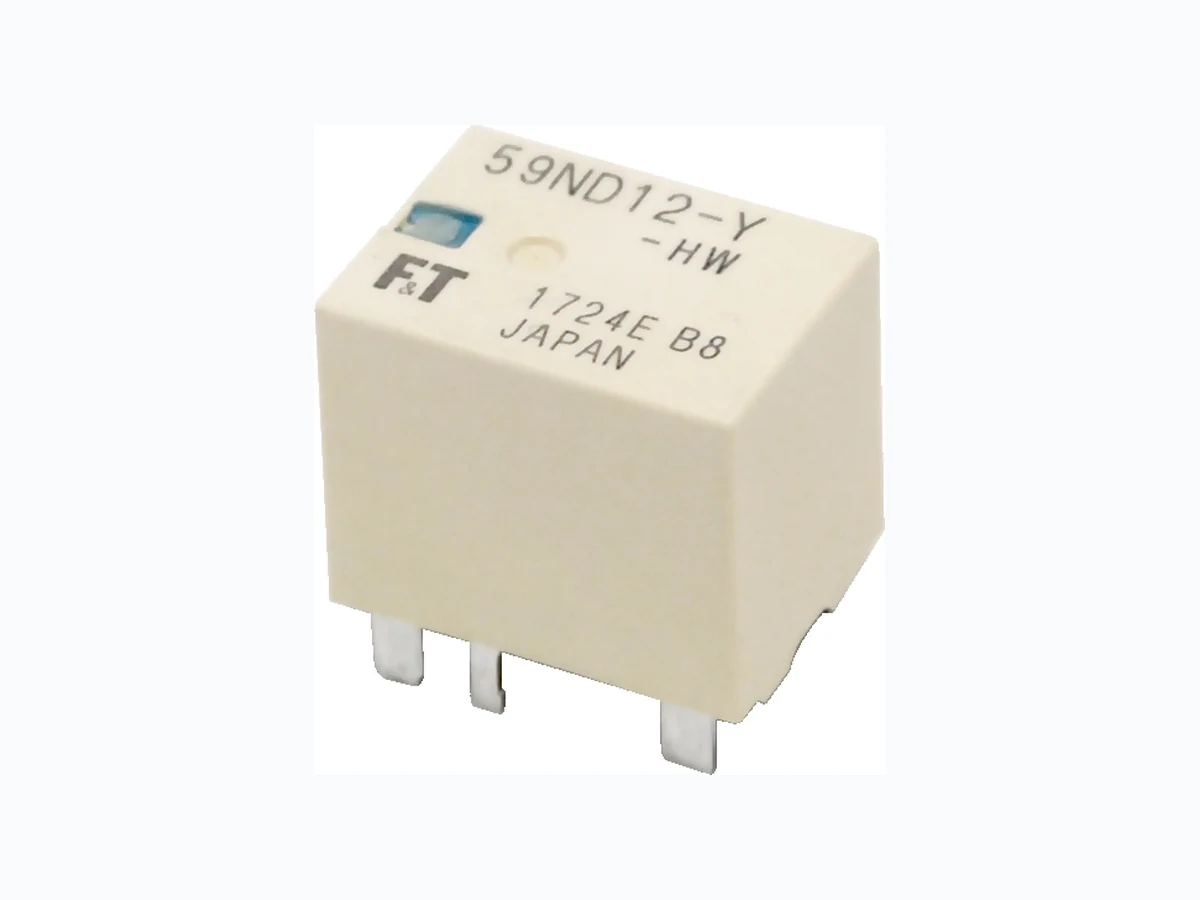
FBR59-HW FCL
Document overview
- Manufacturer or author: Provided By www.digicamel.com(free datasheet download site)
- PDF pages: 8
Technical content
For automotive applications
1 POLE - 70A (For 12V Car Battery)
˙ FEATURES w 1 pole, 70A, 1 form U w High temperature grade (-40˚C to 125˚C) w Comparable capability with Power Mini ISO plug-in relays w Through hole reflow type available w RoHS compliant, lead free Please see page 4 for more information ˙ Part Numbers [Example] FBR59 N D12 - Y - HW - RW (a) (b) (c) (d) (e) (f) (a) Relay type FBR59 : FBR59 series (b) Enclosure N : Plastic sealed type (c) Coil rated voltage D12 : 9...12VDC Coil rating table at page (d) Contact material Y : Silver-tin oxide (e) Contact rating HW : 70A (f) Soldering Nil RW : Standard : Through hole reflow (THR) Actual markings does not carry the type name: "FBR" E.g.: Ordering code: FBR59ND12-Y-HW Actual marking: 59ND12-Y-HW
Item FBR59-HW Remarks / conditions Contact data 1 form U Construction Configuration Single Material Silver-tin oxide Voltage drop Max. 100 mV At 1A, 12VDC Contact rating 70A, 14VDC 45A, 14VDC Resistive load Motor load Max. carrying current 70A / 1h At 25 deg C, rated load Max. inrush current 220A Capacitor inrush based Min. switching load * 1A 6VDC Reference Max. switching load ** 70A, 14VDC 45A, 14VDC Resistive load Motor load Coil Operating temperature range -40ºC ~ +125ºC No frost Timing data Operate Max. 10ms At nominal voltage (without diode, without bounce) Release Max. 10ms At nominal voltage (without diode, without bounce) Storage temperature / humidity -40ºC to 125ºC, 45 to 85RH No frost Life Mechanical Min. 1 x 10⁶ operations without contact load Electrical Min. 50 x 10³ operations at 70A Min. 100 x 10³ operations at 60A resistive load Insula- tion Insulation resistance Min. 100MΩ at 500VDC Initial Dielectric withstanding voltage Open contacts 500VAC (50/60Hz), 1 minute Coil contact 500VAC (50/60Hz), 1 minute Other Vibration resistance Misoperation 10 to 200Hz, 44m/s 2 (4.5G), constant acceleration Endurance 10 to 200Hz, 44m/s2 (4.5G), constant acceleration Shock resis- tance Misoperation Min. 100m/s² (11 ± 1ms) Endurance Min. 1,000m/s² (6 ± 1ms) Dimensions / weight 15.0 x 20.0 x 16.8 mm / approx. 13g Please perform the confirmation test with actual conditions. * : Minimum switching loads mentioned above are reference values. Please perform the confirmation test with actual load before production since reference values may vary according to switching frequencies, environmental conditions and expected reliability levels. : Maximum switching loads mentioned above are reference values. Please refer to operation range graph for continuous current. Note: Values of electrical characteristics are under 15 to 35°C, 25 to 75%RH (JIS standard condition) unless otherwise specified. Note: Care shall be taken on the heat generated on PC board when maximum carrying current exceeds 10A. Specif ications
■ Coil Data code Rated Coil Voltage (VDC) Coil Resistance +/-10%(Ω) Must Operate Voltage* (VDC) Must Release Voltage* (VDC) D09 9 170 5.4 (at 20ºC) 7.7 (at 125ºC) 0.7 (at 20ºC) 1.0 (at 125ºC) D10 10 220 6.3 (at 20ºC) 9 (at 125ºC) 0.8 (at 20ºC) 1.2 (at 125ºC) D12 12 320 7.3 (at 20ºC) 10.4 (at 125ºC) 1.0 (at 20ºC) 1.5 (at 125ºC) Note: All values in the table are valid at 20°C and zero contact current, unless otherwise specified. : Specified operated values are valid for pulse wave voltage. * Note: Please use at rated coil voltage. Please refer to characteristic data and set up adequate voltage in case of use at over voltage. ■ Dimensions
- Dimensions
- Schematics (BOTTOM VIEW) 1 2 4 578 15.3 max. 15.0 typ. 0.5 0.5 12.5 2.5 2.5 3 4.35 9.65 3 (3.6)1.5 20.3 max. 20.0 typ. 17.1 max. / 16.8 typ. 16.2 max. / 15.9 typ. 20.9 max. 20.4 typ. 20.3 max. 20.0 typ. 15.3 max. 15.0 typ.
Layout (BOTTOM VIEW) ( ): Reference value Unit: mm ˙ Characteristic Data (Reference) (3) 4.35 9.65 12.5 2 -2.8×0.85 0 +0.1 2 -1.8×0.85 0 +0.1 2 -2.8×0.85 0 +0.1 2.8 1.8 0.85 0.85 +0.1 +0.1 (R) (R) B B A A Dimensions of the terminals do not include thickness of pre-solder. Tolerance of PC board mounting hole layout : ±0.1 unless otherwise specified. 100 1 2 3 4 5 6 7 8 9 10 11 12 Operate voltage Release voltage FBR59ND12-Y-HW n=50 20 ˆ Distribution of operate/release voltage 100 5 10 15 20 25 30 35 40 45 50 Distribution of contact resistance 100 1 2 3 4 5 6 7 8 9 10 Distribution of operate/release time BNCJFOUUFNQFSBUVSFˆ $POUBDUDVSSFOUDBQBDJUZ0QFSBUJOHSBOHF "QQMJDBCMF WPMUBHFSBOHF 0QFSBUFWPMUBHF DPPMDPJM 7NBYBU ˆ ˆ ˆ ˆ FBR59ND12-Y-HW n=50 20 ˆ '#3/%:)8 ˆ FBR59ND12-Y-HW n=50 20 ˆ '#3/%:)8 Operate time Release time Operate/release voltage (VDC) Contact resistance (mΩ) Time (ms) "QQMJFEUJNF TFD "QQMJFEWPMUBHF 7 Distribution (%) Distribution (%) Distribution (%)$PJMUFNQFSBUVSFSJTF ˆ "QQMJFEWPMUBHF7 "8(Y "DPOUJOVPVTDVSSFOU .BYDPJMUFNQFSBUVSF ˆ "DPOUJOVPVTDVSSFOU
(ambient temperature 25ˆ) Coil temperature rise (ambient temperature 85ˆ) Coil temperature rise (ambient temperature 25ˆ) Contact current capacity 10000 1000 100 1 10 1000 25ˆ 125 ˆ 85ˆ FBR59ND12-Y-HW 25ˆ 5 10 15 20 25 30 FBR59ND12-Y-HW Applied time (min.) Applied time (sec.) Current (A) Applied voltage 16V AWG10 x 2 (connect a wire on each terminal) 12V Coil voltage (V) -50 50 100 130 e (ˆ)rutarepmet tneibmA Operating range Applicable voltage range -40°C min. +125°C max. 45A continuous Coil: 16V max. 60A continuous 70A continuous Operating voltage (Cool condition) (7.3V max., 20°C) Max. coil temperature: 180°C 1000 100 0.1 1 10 Coil temperature rise (°C) 1000 100 Coil temperature rise (°C) Coil temperature rise (°C) Coil power (W) 0.1 1 10 Coil power (W) 70A 60A 45A 30A 15A 0A0A 5ˆ8 erutarepmet tneibmA Applied coil voltage: 8 to 16V Applied contact current: 0 to 60A 70A 60A 45A 5ˆ2 erutarepmet tneibmA Applied coil voltage: 8 to 16V Applied contact current: 0 to 60A 30A 15A
X Applied shock 980m/s² Specification 98m/s2 Make contact (coil de-energized) Make contact (coil energized) Shock resistance characteristics Vibration resistance characteristics Shock application time: 6±1ms half-sine wave Test conditions: Coil energized(12VDC) and de-energized Shock direction: see diagram below Detection level: chatter >1ms Frequency : 10 to 1000Hz Test conditions: Coil energized(12VDC) and de-energized Shock direction: see diagram below Detection level: chatter >1ms Y Z 1.5 1 0.5 0.1 0.01100 10 100 1000 10000 FrequencyʢHzʣ Sweep frequency 1000Hz Max. Specification 10ʙ55Hz No chattering in 10ʙ1000Hz 100m/s2 area Shock direction Shock level (m/s2) Double amplitude (mm) "DDFMFSBUJPO NT
- ROHS Compliance w All relays produced by FCL Components are compliant with RoHS directive 2011/65/EU, including commission delegated directive 2015/863. Lead free solder plating on relay terminals is Sn-3.0Ag-0.5Cu, unless otherwise specified. This material has been verified to be compatible with PbSn assembly process. 2. Recommended lead free solder condition w w Recommended solder for assembly: Sn-3.0Ag-0.5Cu. 3. Moisture Sensitivity w Moisture Sensitivity Level standard is not applicable to electromechanical relays, unless otherwise indicated. 4. Tin Whiskers w Dipped SnAgCu solder is known as presenting a low risk to tin whisker development. No considerable length whisker was found by our in house test. Flow Solder Condition: Important notes for reflow soldering Pre-Heating: maximum 120˚C within 90 sec. Soldering: dip within 5 sec. at 255°C±5°C solder bath Reflow Solder Condition: (Applicable only for reflow capable type) Recommended reflow soldering profile IRS (infrated reflow soldering) Relay must be cooled by air immediately after soldering Solder by Soldering Iron: Soldering Iron: 30-60W Temperature: maximum 340-360˚C Duration: maximum 3 sec. We highly recommend that you confirm your actual solder conditions ɾ All values mentioned in this datasheet are provided under ideal conditions. Please perform the confirmation test before actual use. ɾ Reflow soldering is prohibited for flow soldering type. ɾ Do not use relays in the atmosphere with sulfide gas, chloride gas or nitric oxide. Contact resistance may increase. ɾ Do not use silicon or silicon-containing product or materials near relays. It may cause contact failure. 250 220 170 130Temperature (°C) Max.120 sec. 90 to 120 sec. 20 to 30 sec. (Time) Pre-heating Air cooling Peak temperature: Max.250°C w Temperature shall be measured at PC board upper surface w Temperature at PC board upper surface may be change of PC board, components mounted on the PC board and/ or heating method. Please perfom the confirmation test with your actual PC board. w This reflow solder condition is applicable only for reflow-capable relays. Do not reflow reflow-incapable relays.
Shinagawa Seaside Park Tower 12-4, Higashi-shinagawa 4-chome, Tokyo 140 0002, Japan Tel: +81-3-3450-1682 Email: fcl-contact@cs.fcl-components.com Asia Pacific Web: www.fcl-components.com/en/ Europe FCL COMPONENTS EUROPE B.V. Diamantlaan 25
2132 WV Hoofddorp, Netherlands
Tel: +31-23-556-0910 Email: info.fceu@cs.fcl-components.com FCL COMPONENTS ASIA PTE LTD. No. 20 Harbour Drive, #07-01B Singapore 117612 Tel: +65-6375-8560 Email: fcal@fcl-components.com North and South America FCL COMPONENTS AMERICA, INC.
2055 Gateway Place Suit e 480,
San Jose, CA 95110 USA Tel: +1-408-745-4900 Email: fcai.components@fcl-components.com China FCL COMPONENTS (SHANGHAI) CO., LTD. Unit 1105, Central Park - Jing An, No.329 Heng Feng Road, Shanghai 200070, China Tel: +86-21-3253 0998 Email: fcsh@fcl-components.com © 2024 FCL Components Limited. All rights reserved. All trademarks or registered trademarks are the property of their respective owners. FCL Products are intended for general use, including without limitation, in personal, household and office environments, in buildings and for ordinary use in the industry. FCL Products are not intended to be used in applications where extremely high safety is required (”High Safety Required Applications”), such as, but not limited to, applications in nuclear facilities, in aircraft automatic flight control, in air traffic control, in mass transit system control, in missile launch system, in weapon systems, in medical equipment for life support or any application involving a direct serious risk of physical injury or death. Please do not use FCL Products without securing the sufficient safety and reliability required for the High Safety Required Applications. In addition, FCL shall not be liable against the customer and/or any third party for any claims or damages arising in connection with the use of FCL Products in the High Safety Required Applications. FCL warrants that its Products, if properly used and services, will conform to their specification and will be free from defects in material and workmanship for twelve months from delivery. The implied warranties of merchantability and fitness for a particular purpose and all other warranties, representations and conditions, express or implied by statute, trade usage or otherwise, expect as set forth in this warranty, are excluded and shall not apply to the Products delivered. The contents, data and information in this datasheet are provided by FCL Components Limited as a service only to its user and only for general information purposes. The use of the contents, data and information provided in this datasheet is at the users’ own risk. FCL has assembled this datasheet with care and will endeavor to keep the contents, data and information correct, accurate, compre- hensive, complete and up to date. FCL Components Limited and affiliated companies do however not accept any responsibility or liability on their behalf, nor on behalf of its employees, for any loss or damage, direct, indirect or consequential, with respect to this datasheet, its contents, data, and information and related graphics and the correctness, reliability, accuracy, comprehensiveness, usefulness, availability and completeness thereof. Nor do FCL Components Limited and affiliated companies accept on their behalf, nor on behalf of its employees, any responsibility or liability with respect to these datasheets, its contents, data, information and related graphics and the correctness, reliability, accuracy, comprehensiveness, usefulness, availability and completeness thereof. Rev. February 1, 2024.