


 Download PDF
FBR100UF RFE
Document overview
- PDF pages: 2
Technical content
Page 1
Radial Leaded PPTC FBR Series
FEATURES
- Low hold current, Solid state, Radial leaded product ideal
for up to 90V
- Application: Cable/Telephone Electronics - Cable Power
Passing Tap
- Operation Current: 100mA ~ 900mA
- Maximum Voltage: 90V
- Temperature Range: -40°C to 85°C
- Uncoated (U) type available
ELECTRICAL CHARACTERISTICS (23°C)
RoHS
ü
AGENCY RECOGNITION
- UL (E211981)
- C-UL (E211981)
- TUV (R5004054)
| Part Number | Hold Current | Trip Current | Max Time to Trip | Maximum Current | Rated Voltage | Typical Power | Resistance Tolerance | |
|---|---|---|---|---|---|---|---|---|
| RMIN | R1MAX | |||||||
| IH, A | IT, A | at 5xIH | IMAX, A | VMAX, Vdc | Pd, W | OHMS | OHMS | |
| FBR100(U)F | 0.10 | 0.20 | 10 | 40 | 90 | 0.38 | 2.50 | 7.50 |
| FBR150(U)F | 0.15 | 0.35 | 10 | 40 | 90 | 0.70 | 2.40 | 7.00 |
| FBR200(U)F | 0.20 | 0.45 | 10 | 40 | 90 | 0.80 | 1.50 | 4.50 |
| FBR250(U)F | 0.25 | 0.55 | 10 | 40 | 90 | 0.90 | 1.25 | 3.70 |
| FBR350(U)F | 0.35 | 0.75 | 10 | 40 | 90 | 1.30 | 0.90 | 2.50 |
| FBR550(U)F | 0.55 | 1.20 | 12 | 40 | 90 | 1.50 | 0.45 | 1.50 |
| FBR750(U)F | 0.75 | 1.60 | 13 | 40 | 90 | 1.70 | 0.30 | 1.20 |
| FBR900(U)F | 0.90 | 2.00 | 20 | 40 | 90 | 2.30 | 0.15 | 0.70 |
IH=Hold current-maximum current at which the device will not trip at 23°C still air. IT=Trip current-maximum current at which the device will always trip at 23°C still air. V MAX=Maximum voltage device can withstand without damage at its rated current. I MAX=Maximum fault current device can withstand without damage at rated voltage (V MAX). Pd=Typical power dissipated from device when in the tripped state in 23°C still air environment. R MIN=Minimum device resistance at 23°C. R1MAX=Maximum device resistance at 23°C, 1 hour after tripping. Physical specifications: Lead material: FBR100~FBR350 Tin plated copper, 24 AWG. FBR550~FBR900 Tin plated copper, 20 AWG.
Soldering characteristics: MIL-STD-202, Method 208E. Insulating coating: Flame retardant epoxy, meet UL-94V-0 requirement.
FBR PRODUCTION DIMENSIONS (MILLIMETER)
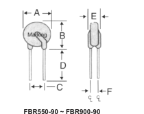
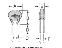
FBR100-90 ~ FBR350-90
Lead Size: 20AWG (0.81mm)
Lead Size: 24AWG (0.51mm)
| Part Number | A | B | C | D | E | F |
|---|---|---|---|---|---|---|
| Maximum | Maximum | Typical | Minimum | Maximum | Typical | |
| FBR100(U)F | 7.4 | 12.7 | 5.1 | 7.6 | 3.1 | 1.4 |
| FBR150(U)F | 9 | 12.7 | 5.1 | 7.6 | 3.6 | 1.4 |
| FBR200(U)F | 9 | 12.7 | 5.1 | 7.6 | 3.6 | 1.4 |
| FBR250(U)F | 9 | 12.7 | 5.1 | 7.6 | 3.6 | 1.4 |
| FBR350(U)F | 9 | 12.7 | 5.1 | 7.6 | 3.6 | 1.4 |
| FBR550(U)F | 10.9 | 14.0 | 5.1 | 7.6 | 3.6 | 1.4 |
| FBR750(U)F | 11.9 | 15.5 | 5.1 | 7.6 | 3.6 | 1.4 |
| FBR900(U)F | 13.0 | 16.0 | 5.1 | 7.6 | 3.6 | 1.4 |
U suffix = uncoated
C5EB07
RFE International • Tel:(949) 833-1988 • Fax:(949) 833-1788 • E-Mail Sales@rfeinc.com
REV 03.01. 2007
Page 2
Radial Leaded PPTC
RoHS
ü
FBR Series
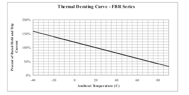
THERMAL DERATING CURVE
TYPICAL TIME-TO-TRIP AT 23°C
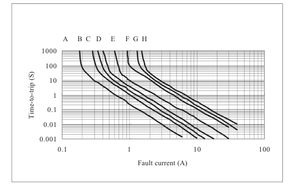
A= FBR100(U) B= FBR150(U) C= FBR200(U) D= FBR250(U) E= FBR350(U) F= FBR550(U) G= FBR750(U) H= FBR900(U)
NOTE: All Specification subject to change without notice.
C5EB07
RFE International • Tel:(949) 833-1988 • Fax:(949) 833-1788 • E-Mail Sales@rfeinc.com
REV 03.01. 2007