

 Download PDF
FBO40-12N IXYS
Document overview
- PDF pages: 2
Technical content
Page 1
Advanced Technical Information
Single Phase
Rectifier Bridge
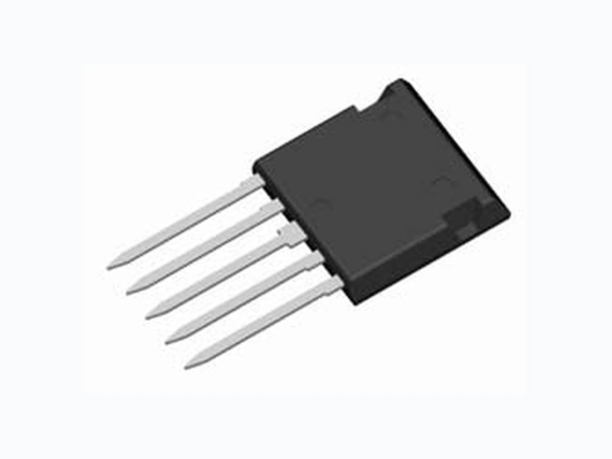
in ISOPLUS i4-PACTM
Rectifier Bridge
Symbol
Conditions
VRRM
TC = 90°C; sine 180° (per diode)
IFAV
TC = 90°C
ID(AV)M
TVJ = 25°C; t = 10 ms; sine 50 Hz
IFSM
TC = 25°C
(per diode)
Ptot
Symbol
Conditions
FBO40-12N
VRRM
= 1200 V
ID(AV)M = 40 A
= 250 A
IFSM
Features
- rectifier diodes for line frequency
Maximum Ratings
- ISOPLUS i4-PACTM package
1200
V - isolated back surface - low coupling capacity between pins
20 A and heatsink
40 A - enlarged creepage towards heatsink
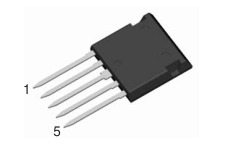
250 A - application friendly pinout
55 W - high reliability - industry standard outline
Applications
Characteristic Values
(TVJ = 25°C, unless otherwise specified)
- single phase mains rectifiers
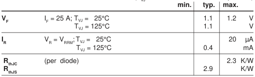
Data according to IEC 60747 refer to a single diode unless otherwise stated
IXYS reserves the right to change limits, test conditions and dimensions.
© 2001 IXYS All rights reserved
- power factor correction in conjunction with boost chopper (FID.../FMD... type)
1 - 2
Page 2
Component
Symbol
Conditions
TVJ Tstg
IISOL ≤ 1 mA; 50/60 Hz
VISOL
mounting force with clip
FC
Symbol
Conditions
FBO 40-12N
Maximum Ratings -55...+150
°C
-55...+125
°C 2500 V~
20...120
N
Characteristic Values
| min. | typ. | max. |
|---|---|---|
| C coupling capacity between shorted p pins and mounting tab in the case | 40 | pF |
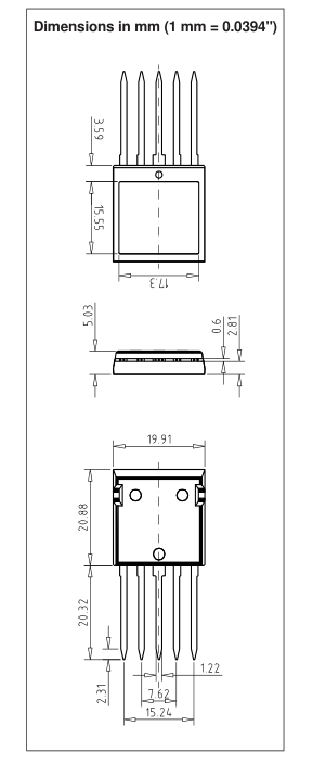
| d ,d pin - pin 1.7 S A d ,d pin - backside metal 5.5 S A | mm mm | |
| Weight | 9 | g |
F4 - 2
© 2000 IXYS All rights reserved