

 Download PDF
FAB ETC
Document overview
- Manufacturer or author: Provided By www.digicamel.com(FREE DATASHEET DOWNLOAD SITE)
- PDF pages: 22
Technical content
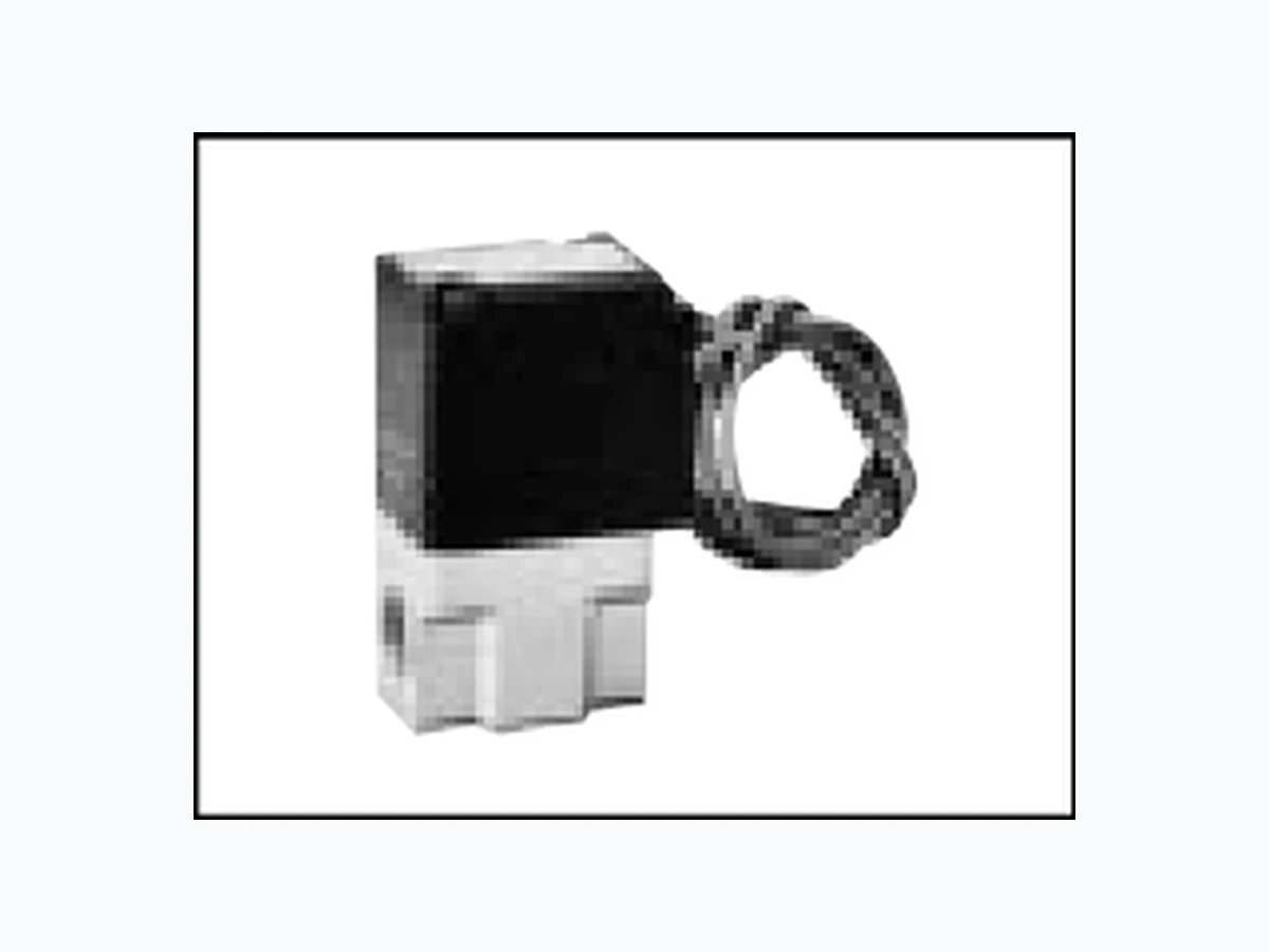
Discrete direct acting 2 port solenoid valve for compressed air, manifold (special purpose valve) FAB Series NC (normally closed) type, NO (normally open) type Port size: M5, Rc1/8 to Rc1/2 Refer to Ending 17 for more details. Common specifications Descriptions Compressed air 0 to 1.4 (Refer to the maximum working pressure differential on the individual specifications) 2.1 (1.5 for FAB11/21) AC: -10 to 60, DC: -10 to 40 (no freezing) AC: -20 to 60, DC: -20 to 40 B No corrosive gas and flammable Direct acting poppet structure 0.2 or less Free IP65 or equivalent (Note 1) 1.5 1.5 0.12 0.28 0.28 0.55 0.55 1.2 3.1 1.2 2.1 5.7 2.1 3.1 5.7 5.5 0.57 1.2 3.0 1.2 2.1 5.2 2.1 3.0 5.2 0.64 0.52 0.52 0.59 0.56 0.56 0.50 0.56 0.54 0.48 0.54 0.50 0.48 0.41 0.53 0.57 0.48 0.50 0.54 0.41 0.54 0.52 0.41 0.7 0.3 1.0 0.6 1.4 1.0 0.3 1.4 1.0 0.25 1.2 0.7 0.3 0.15 1.1 0.55 0.2 0.9 0.55 0.15 0.8 0.5 0.25 0.7 0.3 1.0 0.6 1.4 0.6 0.15 1.4 0.9 0.15 1.2 0.8 0.3 0.15 1.1 0.55 0.2 0.9 0.55 0.15 0.8 0.5 0.25 FAB JIS symbol NC (normally closed) type IN OUT IN OUT MPa MPa cm3/min. (ANR) Individual specifications FAB11- M5 FAB21- 6 FAB31- FAB41- FAB51- 10 FAB51- FAB32- FAB42- FAB52- Port size Orifice (mm) AC DC 50Hz 3.4 5.3 7.5 11.5 Voltage Model no. FAB1 FAB2 FAB3/4/5 2mA or less 3mA or less 6mA or less 1 mA or less 1.5mA or less 3 mA or less 1mA or less 2mA or less
100 VAC 200 VAC 24 VDC 12 VDC
1.0 1.4 1.4 2.6 5 4.6 2.3/1.6 Rc 1/8 Rc 3/8 Rc 1/8 Rc 1/4 Rc 1/8 Rc 1/4 Rc 1/4 Rc 3/8 Rc 1/4 Rc 3/8 Rc 3/8 Rc 1/2
100 VAC
110 VAC
200 VAC
220 VAC
24 VDC
12 VDC
30 . 0 7 3.7 10 9 2.7/2 40 . 1 2 5.5 20 17 4/3.4 6.5 0.21 11 40 35 7.5/6.5 80 . 3 7 16 55 45 11/9.5 11.5 0.60 82 5 2 2 4.6/3.2 60 . 3 1 14 45 40 7.5/6.5 80 . 5 4 20 60 50 11/10 11.5 0.71 60Hz 50Hz 60Hz AC 50/60Hz DC Weight (kg) Max. working pressure MPa Rated voltage Power consumption (W) At holding At starting Max. working pressure differential MPa C[dm3/(s bar)] b Flow characteristics Rated electric power (VA)Descriptions Model no. Working fluid Working pressure differential range Withstanding pressure (water pressure) Fluid temperature Ambient temperature Heat proof class Atmosphere Valve structure Valve seat leakage Installation attitude Protective structure *1: Use the allowable voltage fluctuation range within 10% of the rated voltage. *2: The leakage current must be less than values given at right. *3: 8.6 (W) for 12 VDC. *4: Effective sectional area S and sonic conductance C are converted as S 5.0 x C. NO (normally open) type Leakage current NC (normally closed) type NO (normally open) type Note 1: The T-type terminal box type is IP61 or equivalent, and the FAB11 compact terminal box type is IP40 or equivalent.
Other G.P. systems HNB/G USB/G FAB/G FGB/G FVB FWB/G FHB FLB AB AG AP/AD CHB/G MXB/G APK/ ADK Special purpose valve for compressed air Direct acting 2 port solenoid valve Note on model no. selection *1: For the FAB51 orifice П4mm (item (D) 5), П5mm (item (D) 6), only the Rc3/8 (item (C) 10) bore size is available. *2: For item (E) 1, only NC is available. For item (E) 0, only NO is available. *3: For FAB11 item (F) 2G, the compact terminal box (G1/4) is used. *4: For FAB21 item (F) 2G and 2HS, the compact terminal box (Pg9) is used. *5: For item (F) 2CS, the surge suppressor is built into the coil, and for 2HS and 3RS, it is built into the terminal box. *6: Only the NC (normally closed) type manual override is available. *7: Consult with CKD for other voltages that cannot be manufactured. <Example of model number> FAB21-6-1-12CAB-1 Model: FAB A Size variation : 22 mm B Actuation : NC (normally closed) type C Port size : Rc 1/8 D Orifice : 1.5 E Body, sealant combination : Body - aluminum, sealant - NBR F Coil option : Grommet lead wire G Manual override : Manual lock type H Other options : Mounting plate I Voltage : 100 VAC 50/60Hz, 110 VAC 60Hz How to order Voltage F A A B 1 Working fluid (Compressed air) Other options No. of port (2 port valve) A Size variation B Actuation C Port size D Orifice E Body, sealant combination F Coil option G B 2 1 6 1 2C1 H I Manual override*6 DescriptionsSymbol 18 mm 22 mm 28 mm 34 mm 40 mm Standard Standard OptionOptionOption Standard Grommet lead wire Grommet lead wire with surge suppressor DIN terminal box (Pg11) DIN terminal box with light and surge suppressor (Pg11) Conduit (CTC19) Conduit (G1/2) T type terminal box (G1/2) T type terminal box with light and surge suppressor (G1/2) None Manual lock type Manual non-locking type None Mounting plate NC NO Actuation NBR NBR SealantBody Aluminum Brass F A B F A B F A B F A B F A B F A B NC (normally closed) type NO (normally open) type Rc 1 / 8 Rc 1 / 4 Rc 3 / 8 Rc 1 / 2 Z 2CS 2HS 2CG 2CH 3RS Blank A N Blank B 1.5
100 VAC 50/60Hz, 110 VAC 60Hz
200 VAC 50/60Hz, 220 VAC 60Hz
F A B F A B 213141 51324252 For voltages other than the above, write in the voltage directly. Model no. Select from the combination of marks in the above table. A I H G F E D C B Actuation Size variation Port size Coil option Body, sealant combination Orifice Manual override Other options Voltage
FAB*1 Series: NC (normally closed) type Internal structure and parts list Dimensions (Page 114) FAB*1 series Coil assembly Plunger assembly O ring Spring Body Parts name SUS, NBR NBR SUS ADC Stainless steel, nitrile rubber Nitrile rubber Stainless steel Aluminum alloy die-casting MaterialsNo. FAB11 FAB21 FAB31 FAB41 FAB51 A B C 53.5 74.5 D 43.5 65.5 90.5 E 15.5 18.5 22.5 F 19.5 22.5 29.5 G H Rc1/8 Rc1/8, Rc1/4 Rc1/4, Rc3/8 Rc3/8, Rc1/2 J K M4 depth 5.5 M4 depth 6 M5 depth 6 M5 depth 7 M5 depth 8 LModel no. Grommet lead wire type FAB*1-*-*-*2C IN OUT IN OUT FG A View A C D E B H J OUT View A L * Lead wire length 300mm K
FAB*1 Series: NC (normally closed) type SAB/ SVB Explosion proof For dry air HVB/ HVL NP/NAP/ NVP PD/FAD/ PJ CVE/ CVSE CPE/ CPDCustom order Medical analysis Other G.P. systems HNB/G USB/G FAB/G FGB/G FVB FWB/G FHB FLB AB AG AP/AD CHB/G MXB/G APK/ ADK Special purpose valve for compressed air Direct acting 2 port solenoid valve 99.5 FAB31 FAB41 FAB51 A 60.5 64.5 B 48.5 57.5 71.5 C 74.5 83.5 97.5 D EModel no. 4.5 4.5 5.5 5.5 5.5 1.2 1.2 1.6 1.6 1.6 FAB11 FAB21 FAB31 FAB41 FAB51 ABCDEFGHJKLModel no. 24.5 26.5 29.5 37.5 FAB11 FAB21 FAB31 FAB41 FAB51 A BModel no. 58.5 65.5 FAB11 FAB21 FAB31 FAB41 FAB51 A 28.5 50.5 B C 36.5 55.5 D E G1/4 Pg 9 Pg11 Pg11 Pg11 FModel no. 46.5 FAB31 FAB41 FAB51 A 48.5 57.5 71.5 B C CTC19 G1/2 DModel no. CTC19 G1/2 CTC19 G1/2 Grommet lead wire with surge suppressor FAB*1-*-*-* 2CS DIN terminal box (with light and surge suppressor) FAB*1-*-*-* 2G 2HS Conduit (CTC19, G1/2) FAB*1-*-*-* 2CG 2CH T type terminal box (with light and surge suppressor) (G1/2) FAB*1-*-*-* 3T 3RS Mounting plate Manual override locking/non-locking N IN OUT AB OUT IN OUT OUT F A B D C IN OUT A B D OUT F A B C D 4-G6-H J K E L Note: Non-locking is available for size variation 3, 4 and 5. IN OUT Manual override A IN G1/2 C D E (coil width)C (coil width) E (coil width) OUT Optional dimensions (Page 114) (For common dimensions, refer to the grommet lead wire dimensions on the left page.)
FAB*2 Series: NO (normally open) type Internal structure and parts list FAB*2 series Dimensions (Page 114) Grommet lead wire type FAB*2-*-*-*2C OUTIN Coil assembly Core assembly Valving element guide assembly O ring Spring Body Parts name SUS, Cu PPS, SUS, NBR NBR SUS C3771 Stainless steel, copper Polyphenylene sulfite, stainless steel, nitrile rubber Nitrile rubber Stainless steel Brass MaterialsNo. FAB32 FAB42 FAB52 A B C 62.5 71.5 D 103.5 E 18.5 22.5 F 22.5 29.5 G H Rc1/8, Rc1/4 Rc1/4, Rc3/8 Rc1/4, Rc3/8 J K M5 depth 6 M5 depth 8 M5 depth 8 LModel no. H B J L K * Lead wire length 300mm View A FG D C E A IN OUT View A
FAB*2 Series: NO (normally open) type SAB/ SVB Explosion proof For dry air HVB/ HVL NP/NAP/ NVP PD/FAD/ PJ CVE/ CVSE CPE/ CPDCustom order Medical analysis Other G.P. systems HNB/G USB/G FAB/G FGB/G FVB FWB/G FHB FLB AB AG AP/AD CHB/G MXB/G APK/ ADK Special purpose valve for compressed air Direct acting 2 port solenoid valve Optional dimensions (Page 114) (For common dimensions, refer to the grommet lead wire dimensions on the left page.) DIN terminal box (with light and surge suppressor) FAB*2-*-*-* 2G 2HS 29.5 37.5 FAB32 FAB42 FAB52 A BModel no. Grommet lead wire with surge suppressor FAB*2-*-*-* 2CS A B IN OUT OUT 99.5 FAB32 FAB42 FAB52 A 60.5 64.5 B C 101 D EModel no. 5.5 5.5 1.6 1.6 FAB32 FAB42/52 ABCDEFG KModel no. 58.5 65.5 FAB32 FAB42 FAB52 A 50.5 B C 56.5 73.5 D E Pg11 Pg11 Pg11 FModel no. T type terminal box (with light and surge suppressor) (G1/2) FAB*2-*-*-* 3T 3RS Mounting plate ABCDEFG HJ L A B IN C D F IN A B G1/2 OUT C D E (coil width) E (coil width) J K 4-G6-H F B A C D E L 46.5 FAB32 FAB42 FAB52 A B C CTC19 G1/2 DModel no. CTC19 G1/2 CTC19 G1/2 Conduit (CTC19, G1/2) FAB*2-*-*-* 2CG 2CH ABCD B A D IN OUT C (coil width)
Direct acting 2 port solenoid valve for compressed air, manifold (special purpose valve) GFAB Series NC (normally closed) type Port size: M5, Rc1/8, Rc1/4, Rc3/8 Common specifications Descriptions Compressed air 0 to 1.4 (Refer to the maximum working pressure differential on the individual specifications) 2.1 (1.5 for GFAB11/GFAB21) AC: -10 to 60, DC: -10 to 40 (no freezing) AC: -20 to 40, DC: -20 to 40 B No corrosive gas and flammable Direct acting poppet structure 0.2 or less Free IP65 or equivalent (Note 1) 1.5 1.5 0.15 0.31 0.31 0.53 0.55 1.2 2.1 1.2 2.1 3.5 2.1 3.0 4.4 0.54 0.49 0.49 0.38 0.48 0.39 0.27 0.39 0.34 0.21 0.34 0.22 0.18 0.7 0.3 1.0 0.6 1.4 1.0 0.3 1.4 1.0 0.25 1.2 0.7 0.3 0.7 0.3 1.0 0.6 1.4 0.6 0.15 1.4 0.9 0.15 1.2 0.8 0.3 GFAB MPa MPa cm3/min. (ANR) Individual specifications GFAB -Z GFAB -1 GFAB -2 GFAB -3 GFAB -5 Port size Port A Port C Orifice (mm) AC DC 50Hz 3.4 5.3 7.5 Voltage Model no. GFAB1 GFAB2 GFAB3/4/5 2mA or less 3mA or less 6mA or less 1mA or less 1.5mA or less 3mA or less 1mA or less 2mA or less 1.0 1.4 Rc 1/8 Rc 1/4 Rc 1/4 Rc 1/4 Rc 1/8 Rc 1/8 Rc 3/8 Rc 3/8 Rc 3/8 3.7 10 9 2.7/2 4 5.5 20 17 4/3.4 6.5 11 40 35 7.5/6.5 8 16 55 45 11/9.5 11.5 60Hz 50Hz 60Hz AC 50/60Hz DC Max. working pressure MPa Rated voltage Power consumption (W) At holding At starting Max. working pressure differential MPa Rated electric power (VA)Descriptions Model no. Working fluid Working pressure differential range Withstanding pressure (water pressure) Fluid temperature Ambient temperature Heat proof class Atmosphere Valve structure Valve seat leakage Installation attitude Protective structure *1: Use the allowable voltage fluctuation range within 10% of the rated voltage. *2: The leakage current must be less than values given below. *3: Effective sectional area S and sonic conductance C are converted as S 5.0 x C. IN OUT Port A Port C Port A IN OUT IN OUT IN OUT Port A Port A Port C JIS symbol NC (normally closed) / common supply type (Port C pressurized) NC (normally closed) / individual supply type (Port A pressurized) 1115 C[dm3/(s bar)] b Flow characteristics Note 1: The T-type terminal box type is IP61 or equivalent, and the GFAB11/GFAB15 compact terminal box type is IP40 or equivalent. Refer to Ending 17 for more details.
Other G.P. systems HNB/G USB/G FAB/G FGB/G FVB FWB/G FHB FLB AB AG AP/AD CHB/G MXB/G APK/ ADK Special purpose valve for compressed air Direct acting 2 port solenoid valve Manifold with masking plate Manifold <Example of model number> Masking plate quantity 1FG A B 2 5 X 1 N 2 5 2C2FG A B 3 1 7 1 N 1 Working fluid (Compressed air) A Size variation B Circuit structure C Orifice No. of port (2 port valve) D Station no. E Body, sealant combination F Coil option G Manual override Solenoid valve quantity How to order *1: For the number of manifold stations, select a number of stations from 2 to 10. *2: For the type with masking plate, designate the item (D) as "X", then designate the number of (I) solenoid valves and (J) masking plates. *3: For GFAB11/15 item (F) 2G, the compact terminal box (G1/4) is used. *4: For GFAB21/25 item (F) 2G and 2HS, the compact terminal box (Pg9) is used. *5: For item (F) CS, the surge suppressor is built into the coil, and for 2HS and 3RS, it is built into the terminal box. *6: Consult with CKD for other voltages that cannot be manufactured. *7: Solenoid valves are arranged from the right side facing the sub-plate A (independent) port. *8: Orders for only the masking plate and sub-plate are also available. Contact CKD for details. Note on model no. selection H Voltage I J A Size variation : 28 mm B Circuit structure : NC (normally closed) / common supply type C Orifice : 2 D Station no. : 7 stations E Body, sealant combination : Body - PPS, sealant - NBR F Coil option : Grommet lead wire G Manual override : Manual non-locking H Voltage : 100 VAC 50/60Hz, 110 VAC 60Hz I J : No masking plate DescriptionsSymbol Model no. G F A B G F A B G F A B G F A B G F A B 18 mm 22 mm 28 mm 34 mm 40 mm NC (normally closed) / common supply type NC (normally closed) / individual supply type Z Blank N Blank Blank 2CS 2HS 2CG 2CH 3RS 1.5 X 2 stations 10 stations Actuator only With masking plate Standard Standard Option Option Grommet lead wire Grommet lead wire with surge suppressor DIN terminal box (Pg11) DIN terminal box with light and surge suppressor (Pg11)Conduit (CTC19) Conduit (G1/2) T type terminal box (G1/2) T type terminal box with light and surge suppressor (G1/2) None Manual non-locking type SealantBody to to to to to to NBRPPS Select from the combination of marks in the above table. For voltages other than the above, write in the voltage directly. B C E F G A D H I J Orifice Coil option Voltage Solenoid valve quantity Size variation Circuit structure Station no. Body, sealant combination Manual override Masking plate quantity
Internal structure and parts list GFAB actuator GFAB manifold Coil assembly Plunger assembly O ring Spring Parts name SUS, NBR NBR SUS Stainless steel, nitrile rubber Nitrile rubber Stainless steel MaterialsNo. Body Gasket Sub-plate Parts name PPS NBR A6063 Polyphenylene sulfite Nitrile rubber Aluminum MaterialsNo. OUT IN
Other G.P. systems HNB/G USB/G FAB/G FGB/G FVB FWB/G FHB FLB AB AG AP/AD CHB/G MXB/G APK/ ADK Special purpose valve for compressed air Direct acting 2 port solenoid valve Dimensions: Manifold (Page 114) Grommet lead wire type GFAB**-*-*-12C Dimensions: Actuator Grommet lead wire type GFAB**-*-0-12C (Page 114) GFAB1 GFAB2 GFAB3 GFAB4 GFAB5 A 28.5 B C 15.5 18.5 22.5 D 19.5 22.5 29.5 E FModel no. AA BB AA BB AA BB AA BB AA BB GFAB1 GFAB2 GFAB3 GFAB4 GFAB5 Sym. Stn. no. 100 100 114 106 120 124 138 146 160 110 120 138 152 162 176 192 206 108 118 136 146 170 184 200 214 238 252 128 138 162 172 202 216 238 252 284 298 148 158 188 198 234 248 276 290 330 344 168 178 214 224 266 280 314 328 376 390 188 198 240 250 298 312 352 366 422 436 208 218 266 276 330 344 390 404 468 482 891 0Model no. GFAB1 GFAB2 GFAB3 GFAB4 GFAB5 Rc1/8 Rc1/8 Rc3/8 Rc3/8 Rc3/8 44.5 15.5 18.5 22.5 19.5 22.5 29.5 21.5 34.5 Rc1/8 Rc1/4 Rc1/4 Rc1/4 4.5 4.5 6.5 6.5 6.5 6.5 11.5 ABCDEFGHJK LMNPQRSTModel no. Lead wire length 300mm GH B A 2-C (Port C)D E F JK L M R NP AA BB n-Q (Port A) 2-S T A B C DE F * Lead wire length 300mm
Actuator installation dimension drawing GFAB1*/2*/3* GFAB4*/5* 20 and over 26 and over 32 and over 5 0.15 8 0.15 13 0.15 12.4 0.1 15.5 0.1 20 0.1 14.4 0.1 18.4 0.1 23.6 0.1 10 0.15 10 0.15 11.4 0.15 11.2 0.1 12.4 0.1 15 0.1 17 0.1 19.4 0.1 24.2 0.1 3 or less 3.5 or less 5.5 or less GFAB1 GFAB2 GFAB3 ABCD EFGHModel no. JK M2.5 effective thread depth 5.5 and over M3 effective thread depth 6 and over M4 effective thread depth 5.5 and over 1.6 depth 2.5 0.5 1.6 depth 2.5 0.5 2.1 depth 2.5 0.5 38 and over 46 and over 7 0.2 8 0.2 25 0.1 30 0.1 26 0.1 30 0.1 8.8 0.2 11.5 0.2 11 0.2 14.5 0.2 28 0.1 33 0.1 37 0.1 43 0.1 GFAB4 GFAB5 ABCDEFGHModel no. 8 or less 11 or less 5 or less 7 or less JK L M M4 effective thread depth 9 and over M5 effective thread depth 8 and over 2.6 depth 2.5 0.5 2.6 depth 2.5 0.5 Machining drawing, when 2 actuators are used. Machining drawing, when 2 actuators are used. A n-K 2 x 2n-L 2n-J 2n-MB C D G H FE A 2n-H B C D 2n-K 2n-J E F G 0.1 0.1 00.1 0.1 00.1
Other G.P. systems HNB/G USB/G FAB/G FGB/G FVB FWB/G FHB FLB AB AG AP/AD CHB/G MXB/G APK/ ADK Special purpose valve for compressed air Direct acting 2 port solenoid valve Optional dimensions (Page 114) (For common dimensions, refer to the grommet lead wire actuator dimensions on page 35.) 24.5 26.5 29.5 37.5 GFAB1 GFAB2 GFAB3 GFAB4 GFAB5 A BModel no. Grommet lead wire with surge suppressor GFAB**-*-*-1 2CS A B 46.5 GFAB3 GFAB4 GFAB5 A 42.5 B C CTC19 G1/2 DModel no. CTC19 G1/2 CTC19 G1/2 Conduit (CTC19, G1/2) GFAB**-*-*-1 2CG 2CH A C (coil width) D B 58.5 65.5 GFAB1 GFAB2 GFAB3 GFAB4 GFAB5 A 28.5 50.5 B C 26.5 26.5 33.5 40.5 50.5 D E G1/4 Pg9 Pg11 Pg11 Pg11 FModel no. DIN terminal box (with light and surge suppressor) GFAB**-*-*-1 2G 2HS A B CD E (coil width) F 99.5 GFAB4 GFAB5 A 64.5 B 42.5 C 68.5 D EModel no. T type terminal box (with light and surge suppressor) (G1/2) GFAB**-*-*-1 3T 3RS A B C D E (coil width) G1/2 Manual override (non-locking) Position of manual override Common supply type: Opposite side of Port A Individual supply type: Prot A side Manual override
Discrete direct acting 3 port solenoid valve for compressed air (special purpose valve) FAG Series Universal type, NC pressurization type Port size: M5, Rc1/8, Rc1/4, Rc3/8 Common specifications Descriptions Compressed air 0 to 1.4 (Refer to the maximum working pressure differential on the individual specifications) 2.1 (1.5 for FAG11/FAG21) AC: -10 to 60, DC: -10 to 40 (no freezing) AC: -20 to 60, DC: -20 to 40 B No corrosive gas and flammable Direct acting poppet structure 0.2 or less Free IP65 or equivalent (Note 1) 0.8 1.5 1.5 1.5 0.08 0.28 0.13 0.52 0.32 0.55 1.2 0.55 1.2 2.1 0.55 1.2 2.1 0.32 0.55 1.2 0.55 1.2 2.1 0.61 0.40 0.58 0.54 0.58 0.48 0.57 0.48 0.57 0.48 0.48 0.57 0.48 0.58 0.48 0.57 0.48 0.57 0.48 0.7 0.2 0.7 0.15 0.7 0.4 0.2 0.7 0.3 0.15 1.2 (0.6) 0.6 (0.3) 0.3 (0.15) 1.0 0.7 0.3 1.2 0.6 0.3 FAG MPa MPa cm3/min. (ANR) Individual specifications Port size Orifice (mm) 50Hz 3.4 5.3 7.5 7.5 Voltage Model no. FAG1 FAG2 FAG3/4/5 2mA or less 3mA or less 6mA or less 1mA or less 1.5mA or less 3mA or less 1mA or less 2mA or less 1.0 1.4 1.4 2.6 5 4.6 2.3/1.6 Rc 1/8 Rc 1/8 Rc 1/4 Rc 1/8 Rc 1/4 Rc 1/4 Rc 3/8 Rc 1/4 Rc 3/8 Rc 1/4 Rc 3/8
12 VDC100 VAC
110 VAC 60Hz
220 VAC 60Hz
3 0.09 3.7 10 9 2.7/2 4 0.14 5.5 20 17 4/3.4 6.5 0.23 11 40 35 7.5/6.5 8 0.43 16 55 45 11/9.5 11.5 0.63 5.5 20 17 4/3.4 6.5 0.23 11 40 35 7.5/6 8 0.43 60Hz 50Hz 50Hz/60Hz60Hz AC DC Weight (kg) Max. working pressure MPa Rated voltage Power consumption (W) At holding At starting Max. working pressure differential MPa Rated electric power (VA)Descriptions Model no. NC pressurization type Working fluid Working pressure differential range Withstanding pressure (water pressure) Fluid temperature Ambient temperature Heat proof class Atmosphere Valve structure Valve seat leakage Installation attitude Protective structure *1: Use the allowable voltage fluctuation range within 10% of the rated voltage. *2: The maximum working pressure difference at FAG51 NO pressurization is shown in parentheses. *3: The leakage current must be less than values given at right. *4: Effective sectional area S and sonic conductance C are converted as S 5.0 x C. COM NO NC COM NO NC Universal type FAG11 - M5- Y - 0 FAG21 - 6 - Z - 1 FAG31 - - 0 - 1 - 4 FAG41 - - 1 - 4 - 8 FAG51 - - 1 - 4 - 8 FAG33 - - 0 - 1 - 4 FAG43 - - 1 - 4 - 8 NC pressurization type b Flow characteristics C[dm3/(s bar)] JIS symbol Universal type Note 1: The T-type terminal box type is IP61 or equivalent, and the FAG11 compact terminal box type is IP40 or equivalent. Refer to Ending 17 for more details.
Other G.P. systems HNB/G USB/G FAB/G FGB/G FVB FWB/G FHB FLB AB AG AP/AD CHB/G MXB/G APK/ ADK Special purpose valve for compressed air Direct acting 3 port solenoid valve How to order <Example of model number> I Voltage *1: For FAG11 item (F) 2G, the compact terminal box (G1/4) is used. *2: For FAG21 item (F) 2G and 2HS, the compact terminal box (Pg9) is used. *3: For item (F) 2CS, the surge suppressor is built into the coil, and for 2HS and 3RS, it is built into the terminal box. *4: Consult with CKD for other voltages that cannot be manufactured. F A B 1 Working fluid (Compressed air) No. of port (3 port valve) A Size variation B Actuation C Port size D Orifice E Body, sealant combination F Coil option G Manual override 2CG 1 1 Y 1 AM5 Note on model no. selection H Other options FAG11-M5-Y-12CAB-1 Model: FAG A Size variation : 18 mm B Actuation : Universal type C Port size : M5 D Orifice : 0.8 E Body, sealant combination : Body - aluminum, sealant- NBR F Coil option : Grommet lead wire G Manual override : Manual lock type H Other options : Mounting plate I Voltage : 100 VAC 50/60Hz, 110 VAC 60Hz None Manual locking Manual non-locking B C E F G DescriptionsSymbol A 18 mm 22 mm 28 mm 34 mm 40 mm Universal type NC pressurization type Rc 1 / 8 Rc 1 / 4 Rc 3 / 8 Y Z 2CS 2HS 2CG 2CH 3RS Blank A N Blank B 0.8 1.5 D H I Option None Mounting plate NBR SealantBody Aluminum Model no. F A G F A G F A G F A G 21 31 F A G Select from the combination of marks in the above table. For voltages other than the above, write in the voltage directly. Orifice Body, sealant combination Coil option Manual override Other options Voltage Port size Size variation Actuation Standard Standard Option Grommet lead wire Grommet lead wire with surge suppressor DIN terminal box (Pg11) DIN terminal box with light and surge suppressor (Pg11) Conduit (CTC19) Conduit (G1/2) T type terminal box (G1/2) T type terminal box with light and surge suppressor (G1/2)
Internal structure and parts list FAG*1/*3 series Dimensions (Page 114) Grommet lead wire type FAG**-*-*-12C Coil assembly Plunger assembly O ring Spring Body Parts name SUS, NBR NBR SUS ADC Stainless steel, nitrile rubber Nitrile rubber Stainless steel Aluminum alloy die-casting MaterialsNo. Valving element guide assembly Spring O ring Cover Parts name PPS, SUS, NBR SUS NBR ADC Polyphenylene sulfite, stainless steel, nitrile rubber Stainless steel Nitrile rubber Aluminum alloy die-casting MaterialsNo. 13.5 16.5 18.5 60.5 74.5 51.5 72.5 88.5 15.5 18.5 22.5 19.5 22.5 29.5 FAG1 FAG2 FAG3 FAG4 FAG5 ABCDEFGHJ K L M N M4 depth 5.5 M4 depth 6 M5 depth 8 M5 depth 8 M5 depth 8 Model no. M5 x 0.8 Rc1/8 Rc1/8 Rc1/4 Rc1/4 Rc3/8 Rc1/4 Rc3/8 NO COM NC KJ HFG D E C B ANO COM NC NO NC L N M Lead wire length 300mm
Other G.P. systems HNB/G USB/G FAB/G FGB/G FVB FWB/G FHB FLB AB AG AP/AD CHB/G MXB/G APK/ ADK Special purpose valve for compressed air Direct acting 3 port solenoid valve Optional dimensions (Page 114) (For common dimensions, refer to the grommet lead wire dimensions on the left page.) 4.5 4.5 5.5 5.5 5.5 1.2 1.2 1.6 1.6 1.6 FAG1 FAG2 FAG3 FAG4 FAG5 ABCDEFGHJKLModel no. 99.5 FAG3 FAG4 FAG5 A 60.5 64.5 B 55.5 C 81.5 104 D EModel no. 24.5 26.5 29.5 37.5 FAG1 FAG2 FAG3 FAG4 FAG5 A BModel no. 58.5 65.5 FAG1 FAG2 FAG3 FAG4 FAG5 A 28.5 50.5 B C 44.5 76.5 D E G1/4 Pg9 Pg11 Pg11 Pg11 FModel no. 46.5 FAG3 FAG4 FAG5 A 55.5 B C CTC19 G1/2 DModel no. CTC19 G1/2 CTC19 G1/2 T type terminal box (with light and surge suppressor) (G1/2) FAG**-*-*-1 3T 3RS Manual override (locking/non-locking) N Mounting plate Note: Non-locking is available for size variation 3, 4 and 5. Grommet lead wire with surge suppressor FAG**-*-*-1 2CS DIN terminal box (with light and surge suppressor) FAG**-*-*-1 2G 2HS Conduit (CTC19, G1/2) FAG**-*-*-1 2CG 2CH COM NC AB NO NC A B F E (coil width) E (coil width) CDCOM NC NO NO NO NC NO A C (coil width) D NCCOM B NO B A C D NCCOM G1/2 NO C A 4-G F D B E6-H L NC COM Manual override NO NO J K
Direct acting 3 port solenoid valve for compressed air, manifold (special purpose valve) GFAG Series Universal type Port size: M5, Rc1/8, Rc1/4 Common specifications Descriptions Compressed air 0 to 1.2 (Refer to the maximum working pressure differential on the individual specifications) 1.8 (1.5 for GFAG11/GFAG21/GFAG31) AC: -10 to 60, DC: -10 to 40 (no freezing) AC: -20 to 40, DC: -20 to 40 B No corrosive gas and flammable Direct acting poppet structure 0.2 or less Free IP65 or equivalent (Note 1) 0.8 1.5 1.5 0.08 0.25 0.12 0.42 0.28 0.49 0.90 0.50 1.1 1.6 0.50 1.1 1.6 0.55 0.29 0.44 0.19 0.46 0.36 0.20 0.31 0.20 0.14 0.31 0.20 0.14 0.7 0.2 0.7 0.15 0.7 0.4 0.2 0.7 0.3 0.15 1.2 (0.6) 0.6 (0.3) 0.3 (0.15) GFAG Individual specifications GFAG11 - Y - 0 GFAG21 - Z - 1 GFAG31 - 0 - 1 - 4 GFAG41 - 1 - 4 - 8 GFAG51 - 1 - 4 - 8 Port size Orifice (mm)2 port (Individual port) 1.3 port (Common port) 50Hz 3.4 5.3 7.5 Voltage Model no. GFAG1 GFAG2 GFAG3/4/5 2mA or less 3mA or less 6mA or less 1mA or less 1.5mA or less 3mA or less 1mA or less 2mA or less 1.0 1.2 2.6 5 4.6 2.3/1.6 Rc 1/8 Rc 1/4 Rc 1/4 Rc 1/8 Rc1/8 Rc 1/4 Rc 1/4 Rc 1/4 Rc 1/4 3.7 10 9 2.7/2 4 5.5 20 17 4/3.4 6.5 11 40 35 7.5/6.5 8 16 55 45 11 /9.5 11.5 60Hz 50Hz 60Hz AC 50/60Hz DC Max. working pressure MPa Rated voltage Power consumption (W) At holding At starting Max. working pressure differential MPa Rated electric power (VA)Descriptions Model no. Working fluid Working pressure differential range Withstanding pressure (water pressure) Fluid temperature Ambient temperature Heat proof class Atmosphere Valve structure Valve seat leakage Installation attitude Protective structure COM COM NO(1) (2) (2) (3) NC NO NC C[dm3/(s/bar)] b Flow characteristics Note 1: The T-type terminal box type is IP61 or equivalent, and the GFAG11 compact terminal box type is IP40 or equivalent. *1: Use the allowable voltage fluctuation range within 10% of the rated voltage. *2: The maximum working pressure difference at GFAG51 NO pressurization is shown in parentheses. *3: The leakage current must be less than values given below. *4: Effective sectional area S and sonic conductance C are converted as S 5.0 x C. JIS symbol Common supply / common exhaust type MPa MPa cm3/min. (ANR) Refer to Ending 17 for more details.
Other G.P. systems HNB/G USB/G FAB/G FGB/G FVB FWB/G FHB FLB AB AG AP/AD CHB/G MXB/G APK/ ADK GFAG Series Special purpose valve for compressed air Direct acting 3 port solenoid valve *1: For the number of manifold stations, select a number of stations from 2 to 10. *2: For the type with masking plate, designate the item (D) as "X", then designate the number of (I) solenoid valves and (J) masking plates. *3: For GFAG11 item (F) 2G, the compact terminal box (G1/4) is used. *4: For GFAG21 item (F) 2G and 2HS, the compact terminal box (Pg9) is used. *5: For item (F) 2CS, the surge suppressor is built into the coil, and for 2HS and 3RS, it is built into the terminal box. *6: Consult with CKD for other voltages that cannot be manufactured. *7: Solenoid valves are arranged from the right side facing the sub-plate A (independent) port. *8: Orders for only the masking plate and sub-plate are also available. Contact CKD for details. <Example of model number> J Masking plate quantity How to order 2CZFG A G 2 1 5 1 N 1 Working fluid (Compressed air) H Voltage G Manual override F Coil option E Body, sealant combination D Station no. C Orifice No. of port (3 port valve) FG A N 2 141 1G 3 2GX 1 Note on model no. selection Manifold with masking plate Manifold A Size variation B Circuit structure I Solenoid valve quantity GFAG21-Z-5-12CN-1 Model: GFAG A Size variation : 22 mm B Circuit structure : Common supply / common exhaust type C Orifice : 1 D Station no. : 5 stations E Body, sealant combination : Body - PPS, sealant - NBR F Coil option : Grommet lead wire G Manual override : Manual non-locking H Voltage : 100 VAC 50/60Hz, 110 VAC 60Hz I J : Without masking plate DescriptionsSymbol Model no. G F A G G F A G G F A G G F A G G F A G 41 51 18 mm 22 mm 28 mm 34 mm 40 mm Y Z O O X Common supply / common exhaust type1 Standard Option Grommet lead wire Grommet lead wire with surge suppressor DIN terminal box (Pg11) DIN terminal box with light and surge suppressor (Pg11) Conduit (CTC19) Conduit (G1/2) T type terminal box (G1/2) T type terminal box with light and surge suppressor (G1/2) 2CS 2HS 2CG 2CH 3RS Body PPS Sealant NBR1 to to to Standard None Manual non-locking type Blank N Option No masking plate One masking plate Nine masking plates Blank to toto A Size variation B Circuit structure C Orifice D Station no. E Body, sealant combination F Coil option G Manual override H Voltage I Solenoid valve quantity J Masking plate quantity 0.8 1.5 For voltages other than the above, write in the voltage directly. Select from the combination of marks in the above table.
SUS, NBR NBR SUS PPS Stainless steel, nitrile rubber Nitrile rubber Stainless steel Polyphenylene sulfite MaterialsNo. Valving element guide assembly Gasket Holder Spring Sub-plate Parts name PPS, SUS, NBR NBR SUS SUS A6063 Polyphenylene sulfite, stainless steel, nitrile rubber Nitrile rubber Stainless steel Stainless steel Aluminum MaterialsNo. 5 6 Internal structure and parts list GFAG actuator GFAG manifold
Other G.P. systems HNB/G USB/G FAB/G FGB/G FVB FWB/G FHB FLB AB AG AP/AD CHB/G MXB/G APK/ ADK GFAG Series Special purpose valve for compressed air Direct acting 3 port solenoid valve GFAG1 GFAG2 GFAG3 GFAG4 GFAG5 ABC DEFGHJKLMNPQ RSTUModel no. 6.5 6.5 Rc1/8 Rc1/8 Rc1/4 Rc1/4 Rc1/4 55.5 93.5 100 107.5 116 15.5 18.5 22.5 19.5 22.5 29.5 GFAG1 GFAG2 GFAG3 GFAG4 GFAG5 110 120 138 152 162 176 192 206 456789 1 0Model no. AA BB AA BB AA BB AA BB AA BB 100 100 114 106 120 124 138 146 160 108 118 136 146 170 184 200 214 238 252 128 138 162 172 202 216 238 252 284 298 148 158 188 198 234 248 276 290 330 344 168 178 214 224 266 280 314 328 376 390 188 198 240 250 298 312 352 366 422 436 208 218 266 276 330 344 390 404 468 482 18.5 27.5 34.5 38.5 Rc1/8 Rc1/4 Rc1/4 Rc1/4 21.5 Symbol Stn. no. D G H UB A 4-C E F JK L M T R NP RAA BB 2-S n-Q (Port 2) Lead wire length 300mm (Page 114) Grommet lead wire type GFAG*1-*-*-12C 4.5 4.5 6.5 6.5 6.5 Dimensions: Manifold GFAG1 GFAG2 GFAG3 GFAG4 GFAG5 A 33.5 60.5 B 74.5 C 15.5 18.5 22.5 D 19.5 22.5 29.5 E FModel no. Dimensions: Actuator B DE C A F * Lead wire length 300mm (Page 114) Grommet lead wire type GFAG*1-*-0-12C
Actuator installation dimension drawing GFAG1 GFAG2 GFAG3 ABC DEFGHJK L MModel no. 20 and over 26 and over 32 and over + 0.1 + 0.1 + 0.1 + 0.1 + 0.1 + 0.1 + 0.1 + 0.1 + 0.1 M2.5 effective thread depth 5 and over M3 effective thread depth 6 and over M4 effective thread depth 6 and over GFAG4 GFAG5 ABC DEFGHJK L MModel no. 38 and over 46 and over M4 effective thread depth 9 and over M5 effective thread depth 8 and over + 0.1 + 0.1 + 0.1 + 0.1 + 0.1 + 0.1 14.4 0.1 18.4 0.1 23.6 0.1 9 0.15 12 0.15 17 0.15 12.4 0.1 15.5 0.1 20 0.1 11.2 0.1 12.4 0.1 15 0.1 16.4 0.15 20 0.15 24 0.15 17 0.1 19.4 0.1 24.2 0.1 2.5 3.4 2.5 3.4 1.6 depth 2.5 0.5 1.6 depth 2.5 0.5 2.1 depth 2.5 0.5 12 0.1 14.5 0.1 19.5 0.1 26 0.1 30 0.1 11.8 0.15 11.8 0.15 25 0.1 30 0.1 28 0.1 33 0.1 31.8 0.15 31.8 0.15 37 0.1 43 0.1 22 0.15 22 0.15 4.1 4.1 4.1 4.1 2.6 depth 2.5 0.5 2.6 depth 2.5 0.5 GFAG4*/5* GFAG1*/2*/3* Machining drawing, when 2 actuators are used. Machining drawing, when 2 actuators are used. A E F G B D A E F G B C D n-J (COM side) n-K (NC side (or NO side)) n-K (NC side (or NO side)) n-J (COM side) 2n-L 4n-M 2n-L n-H (NO side (or NC side)) 4n-M n-H (NO side (or NC side)) C
Other G.P. systems HNB/G USB/G FAB/G FGB/G FVB FWB/G FHB FLB AB AG AP/AD CHB/G MXB/G APK/ ADK GFAG Series Special purpose valve for compressed air Direct acting 3 port solenoid valve CKD 99.5 GFAG4 GFAG5 A 64.5 B C D EModel no. 24.5 26.5 29.5 37.5 GFAG1 GFAG2 GFAG3 GFAG4 GFAG5 A BModel no. 46.5 GFAG3 GFAG4 GFAG5 A B C CTC19, G1/2 CTC19, G1/2 CTC19, G1/2 DModel no. 58.5 65.5 GFAG1 GFAG2 GFAG3 GFAG4 GFAG5 A 28.5 50.5 B 31.5 36.5 44.5 62.5 G1/4 Pg9 Pg11 Pg11 Pg11 CDEFModel no. Position of manual override : Opposite side of COM port A B B A C (coil width) D D A B F C E (coil width) A D B E (coil width) C G1/2 Manual override (Page 114) T type terminal box (with light and surge suppressor) (G1/2) GFAG*1-*-*-1 3T 3RS Manual override (non-locking) DIN terminal box (with light and surge suppressor) GFAG*1-*-*-1 2G 2HS Conduit (CTC19, G1/2) GFAG*1-*-*-1 2CG 2CH Optional dimensions (For common dimensions, refer to the grommet lead wire actuator dimensions on page 45.) Grommet lead wire with surge suppressor GFAG*1-*-*-1 2CS