

 Download PDF
F31 NICHICON
Document overview
- PDF pages: 1
Technical content
Page 1
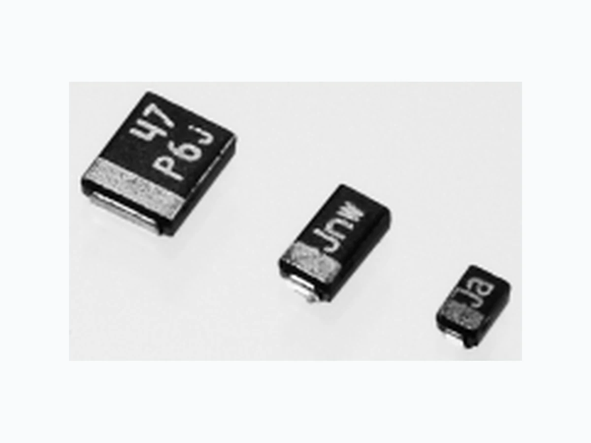
CONDUCTIVE POLYMER TANTALUM SOLID ELECTROLYTIC CAPACITORS
F31
Conductive Polymer Resin-molded Chip,
Compact Series
Adapted to the RoHS directive (2002/95/EC).
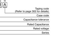
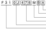
Type numbering system (Example : 6.3V 47µF)
1 2 3 4 5 6 7 8 9 10
Dimensions
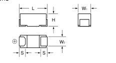
(mm)
Case code
| Case code | L | W1 | W2 | H | S |
| P 2.0 | ±0.2 | 1.25±0.1 | 0.9±0.1 | 1.1±0.1 | 0.5±0.2 |
| A 3.2 | ±0.2 | 1.6±0.2 | 1.2±0.1 | 1.1±0.1 | 0.8±0.2 |
| B 3.4 | ±0.2 | 2.8±0.2 | 2.3±0.1 | 1.1±0.1 | 0.8±0.2 |
Marking
P Case
A Case
B Case
Conductive
Rated Capacitance ( F) µ
Capacitance
Polymer
code
33
Ja
Jar
P6v
Capacitance
Month code
Month Rated
Rated code
Conductive Polymer code Voltage
Voltage
code
code
Rated Voltage (6.3V is marked as "6V")
Standard ratings
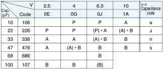
( ) The series in parentheses are being developed.
Please contact to your local Nichicon sales office when these series are being designed in your application.
| Specifica | tion | s | |
| Item | Performance Characteristics | ||
| Category Temperature Range Ð5 | 5 to +105ûC (Rated temperature + 85ûC) | ||
| Capacitance Tolerance ±2 | 0% (120Hz) | ||
| Dissipation Factor(at 120Hz) Re | fer to the list below | ||
| ESR (100kHz) Re | fer to the list below | ||
| A Leakage Current 2 | fter 5 minutes' application of rated voltage, leakage current at 0ûC is not more than 0.1CV | ||
| Ripple Current Re | fer to the list below | ||
| At Damp Heat C (Steady State) D L | 60ûC, 90 to 95% R.H. 500hours (No voltage applied) | ||
| apacitance Change..Within Ð20 to +30% of initial value issipation Factor.......1.5 times Initial specified value or less eakage Current.........Initial specified value or less | |||
| Ð5 C Temperature Cycles D L | 5ûC / +105ûC 30 minutes each 5 cycle | ||
| apacitance Change..Within ±20% of initial value issipation Factor.......Initial specified value or less eakage Current.........Initial specified value or less | |||
| Te Resistance C to Soldering Heat D L | st Condition;10 second reflow at 240ûC | ||
| apacitance Change..Within ±20% of initial value issipation Factor.......1.3 times Initial specified value or less eakage Current.........Initial specified value or less | |||
| Aft the tes Surge req | er application of surge voltage in series with a 1k½ resistor at rate of 30 seconds ON, 30 seconds OFF, for 1000 successive t cycles at 85ûC, capacitors meet the characteristics uirements listed below. Capacitance Change...Within ±20% of initial value Dissipation Factor........Initial specified value or less Leakage Current..........Initial specified value or less | ||
| Aft res Endurance 1 | er 1000 hours' application of rated voltage in series with a 3½ istor at 85ûC. Capacitance Change....Within ±20% of initial value Dissipation Factor...1.5 times Initial specified value or less Leakage Current...Initial specified value or less | ||
| Aft res list Endurance 2 | er 1000 hours' application of rated voltage in series with a 3½ istor at 105ûC,capacitors meet the characteristic requirements ed below Capacitance Change....Within ±20% of initial value Dissipation Factor...3 times Initial specified value or less Leakage Current...Initial specified value or less | ||
| Aft ho ele Shear Test on fou ter | er applying the pressure load of 5N for 10±1 seconds rizontally to the center of capacitor side body which has no ctrode and has been soldered beforehand an aluminum substrate, there shall be nd neither exfoliation nor its sign at the 5N (0.51kg ¥ f) minal electrode. For 10±1 seconds | ||
| Ke do bo the Terminal Strength a s su be the ab | eping a capacitor surface-mounted on a substrate upside wn and supporting the substrate at both of the opposite ttom points 45mm apart from the center of the capacitor, pressure strength is applied with pecified jig at the center of the R230 20 bstrate so that the substrate may nd by 1mm as illustrated. Then, 1mm re shall be found no remarkable 45 45 normality on the capacitor terminals. | ||
∗ As for the surge voltage refer to page 301 for details.
Standard ratings
| Rated Volt (V) | Rated Capacitance (µF) | Case code | Part Number | Leakage Current (µA) | Disspation Factor (%@120Hz) | ESR (m½@100k | Rated Ripple Hz) (mArms@100kHz) |
|---|---|---|---|---|---|---|---|
| 22 | P | F310E226MPA | 5.5 | 6 | 200 | 354 | |
| 33 | A | F310E336MAA | 8.3 | 6 | 150 | 632 | |
| 2.5 | 47 | A | F310E476MAA | 11.8 | 6 | 150 | 632 |
| 100 | B | F310E107MBA | 25.0 | 8 | 70 | 1035 | |
| 10 | P | F310G106MPA | 4.0 | 6 | 200 | 354 | |
| 22 | P | F310G226MPA | 8.8 | 6 | 200 | 354 | |
| 4 | 33 | A | F310G336MAA | 13.2 | 6 | 150 | 632 |
| 47 | B | F310G476MBA | 18.8 | 8 | 70 | 1035 | |
| 100 | B | F310G107MBA | 40.0 | 8 | 70 | 1035 | |
| 10 | P | F310J106MPA | 6.3 | 6 | 200 | 354 | |
| 22 | A | F310J226MAA | 13.9 | 6 | 200 | 548 | |
| 33 | B | F310J336MBA | 20.8 | 8 | 70 | 1035 | |
| 6.3 | 47 | B | F310J476MBA | 29.6 | 8 | 70 (55) | 1035 |
| 68 | B | F310J686MBA | 42.8 | 8 | 70 | 1035 | |
| 10 | A | F311A106MAA | 10.0 | 6 | 200 | 548 | |
| 22 | B | F311A226MBA | 22.0 | 8 | 70 | 1035 | |
| 10 | 33 | B | F311A336MBA | 33.0 | 8 | 70 | 1035 |
| 47 | B | F311A476MBA | 47.0 | 8 | 70 | 1035 |
( ) ESR specification types are also available upon request.
( ) S f
Please contact to your local Nichicon sales office when
CAT.8100X
these series are being designed in your application.