
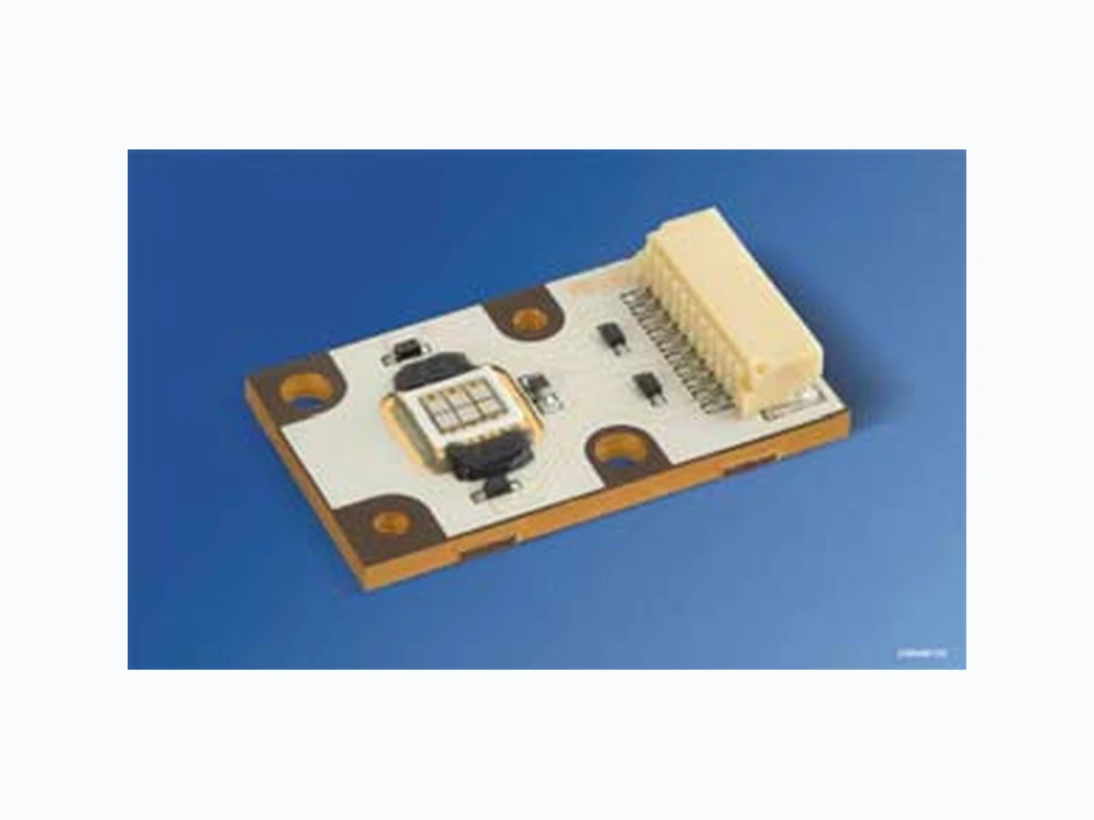
LEABH3AB OSRAM
Document overview
- Manufacturer or author: Provided By www.digicamel.com(FREE DATASHEET DOWNLOAD SITE)
- PDF pages: 17
Technical content
Features
package: compact lightsource in multi chip on board technology; planar sealed feature of the device: outstanding luminance due to pure surface emission and low Rth prepared for additional optics wavelength: 617 nm (amber), 464 nm (blue) viewing angle: Lambertian Emitter (120°) light emitting surface: typ. 2 x 1 mm² (blue); 4 x 1 mm² (amber) technology: Thinfilm InGaAlP (amber), ThinGaN® (blue) Luminance: 26.0*106 cd/m² (amber), 6.7*106 cd/m² (blue) mounting methode: screw holes connector: 10 Pin JST SM10B-SRSS-TB ESD-withstand voltage: up to 2 kV acc. to JESD22-A114-D method of packing: 50 pcs. per tray = packing unit
Applications
projectors medical lighting: surgery light microscope illumination spotlights VMS (variable message signs) high end strobe light
Anm: Die oben genannten Typbezeichnungen umfassen die bes tellbaren Selektionen. Diese bestehen aus einer Helligkeitsgruppe. Es wird nur eine einzige Helligkeitsgruppe und Farbgruppe pro Verpackungsbox geliefert. * Zum Zweck der Bemusterung kann in kleinen Stückz ahlen der konfektionierte JST-Gegenstecker mit Kabel angefordert werden. Note: The above Type Numbers represent the order groups which includes only one brightness group per color and tray. Only one group will be shipped on each tray. *In small amounts for the purpose of sampling the corrsponding connector assembled with cable can be ordered Typ Type Emissionsfarbe Color of Emission Lichstärke pro Farbe1) Seite 17 Luminous Intensity per Color1) page 17 IF = 1000 mA ΙV (cd) amber blue min. typ. min. typ. LE AB H3AB amber blue 56 105 7.1 Bestellinformation
Ordering Information
Lichtfluss pro Farbe2)3) Seite 17 Luminous Flux per Color2)3) page 17 IF = 1000 mA ΦV (lm) amber blue min. typ. min. typ. LE AB H3AB amber blue (168) (326) (21.3) (40) Bestellinformation LE AB H3AB-JBLA-1+EWFW-23 Q65110A6243 LE_ACC_SHR_10V_SR Q65110A4679 (Connector)* Abgekündigt nach OS-PD-2008-008 - wird durch LE AB H3WB ersetzt werden Obsolete acc. to OS-PD-2008-008 - will be replaced by LE AB H3WB Letzte Bestellung / Last Order: 2009-01-10 Letzte Lieferung / Last Delivery: 2009-07-10
Betriebstemperatur* Operating temperature range* Tboard, op – 40 … + 85 °C Lagertemperatur Storage temperature range Tboard, stg – 40 … + 85 °C Sperrschichttemperatur Junction temperature Tj 125 °C Durchlassstrom pro Chip DC Forward current per chip DC (Tboard =25°C) IF 1000 mA Stoßstrom pro Chip DC Surge current per chip DC t ≤ 10 μs, D = 0.1; TA=25°C IFM 2000 mA Sperrspannung pro Chip DC Reverse voltage per chip DC (Tboard=25°C) VR 0.5 V Sperrstrom Reverse current VR = 0.5 V IR 10 mA Leistungsaufnahme pro Farbe Power consumption per Color (Tboard=25°C) Ptot 15.5 10 W * Eine Betauung des Moduls muss vermieden werden. Condensation on the module has to be avoided. Kennwerte Charakteristics Bezeichnung Parameter Symbol Symbol Werte Values Einheit Unit Wärmewiderstand des gesamten Moduls Thermal resistance of the module Sperrschicht / Bodenplatte Junction / base plate Rth JB 2.0 (typ.) K/W
(Tboard = 25 °C) Bezeichnung Parameter Symbol Symbol Werte Values Einheit Unit amber blau Wellenlänge des emittierten Lichtes (typ.) Wavelength at peak emission IF = 1000 mA λpeak 627 460 nm Dominantwellenlänge4) Seite 17 (min.) Dominant wavelength4) page 17 (typ.) IF = 1000 mA (max.) λdom λdom λdom 613 617 625 456 464 469 nm nm nm Spektrale Bandbreite bei 50 % ΙVrel max (typ.) Spectral bandwidth at 50 % ΙVrel max IF = 1000 mA Δλ 24 27 nm Abstrahlwinkel bei 50 % ΙV (Vollwinkel) (typ.) Viewing angle at 50 % ΙV 2ϕ 120 120 Grad deg. Durchlassspannung pro Chip5) Seite 17 (min.) Forward voltage per Chip5) page 17 (typ.) IF = 1000 mA (max.) VF VF VF 2.25 2.8 3.85 3.2 4.0 5.0 V V V Temperaturkoeffizient von λpeak (typ.) Temperature coefficient of λpeak IF = 1000 mA; –10°C ≤ T ≤ 100°C TCλpeak 0.14 0.05 nm/K Temperaturkoeffizient von λdom (typ.) Temperature coefficient of λdom IF = 1000 mA; –10°C ≤ T ≤ 100°C TCλdom 0.08 0.02 nm/K Temperaturkoeffizient von VF pro Chip (typ.) Temperature coefficient of VF per chip IF = 1000 mA; –10°C ≤ T ≤ 100°C TCV – 2.5 – 4.5 mV/K Optischer Wirkungsgrad ohne Linse Optical efficiency without Lens (typ.) IF = 1000 mA ηopt 5.2 lm/W Abstrahlende Fläche (typ.) Radiating Surface AColor 4 x 1 2 x 1 mm² Leuchtdichte Luminance (typ.) IF = 1000 mA LV 26.0*106 6.7*106 cd/m²
RT = NTC resistance in Ω at temperature T in K RN = NTC resistance in Ω at rated temperature TN in K (TN = 298 K for test condition) T, TN = temperature in K e = base of the natural logarithm (e = 2.71828) B = B value, material specific constant of the NTC thermistor Typische Thermistor Kennlinie2) 7) Seite 17 Typical Thermistor Graph2) 7) page 17 IF = f (VF); Tboard = 25 °C SMD NTC Thermistors SMD NTC Thermistors R25 [Ω] No. of R/T characteristic B25/50 [K] B25/85 [K] Resistance Tolerance Δ RN/RN B value Tolerance Δ B/B PNTC,max,25 [mW] 10k EPCOS 8502 3940 3980 ± 5% ± 3% 180 * for further information please visit www.epcos.com RT RN e B 1 T--- 1 TN ⎛⎞⋅ BB NT⁄ TT N⋅ RT 00˚ C T R Ω OHL02609 NTC 1000 2000 3000 4000 5000 6000 7000 10000 10 20 30 40 50 60 70 90
Helligkeits-Gruppierungsschema Brightness Groups Helligkeitsgruppe Brightness Group Lichtstärke1) Seite 17 Luminous Intensity1) page 17 IV (cd) Lichtstrom2) 3) Seite 17 Luminous Flux2) 3) page 17 ΦV (lm) amber JB KA KB LA 56 ... 71 71 ... 90 90 ... 112 112 ... 140 190 (typ.) 240 (typ.) 300 (typ.) 380 (typ.) blue EW FW 25.0 (typ.) 45.0 (typ.) Anm.: Die Standardlieferform von Serientypen beinhal tet eine Familiengruppe. Diese besteht aus nur wenigen Helligkeitsgruppen. Einzelne Helligkeitsgruppen sind nicht bestellbar. Note: The standard shipping format for serial types includes a family group of only a few individual brightness groups. Individual brightness groups cannot be ordered. Wellenlängengruppen (Dominantwellenlänge)4) Seite 17 Wavelength Groups (Dominant Wavelength)4) page 17 Gruppe Group blue min. [nm] max. [nm] 2 456 462 3 462 469 Gruppenbezeichnung auf Etikett Group Name on Label Beispiel: KA-1+FW-2 Example: KA-1+FW-2 Helligkeitsgruppe Brightness Group KA-1+FW-2 Anm.: In einer Verpackungseinheit ist immer nur eine Gruppe für jede Selektion enthalten. Note: No packing unit ever contains more than one group for each selection.
Relative spektrale Emission2) Seite 17 Relative Spectral Emission2) page 17 V(λ) = spektrale Augenempf indlichkeit / Standard eye response curve Irel = f (λ), Tboard = 25 °C, IF = 1000 mA Abstrahlcharakteristik2) Seite 17 Radiation Characteristic2) page 17 Φrel = f (ϕ); Tboard = 25 °C 400 550 450 500 600 650 nm λ 700 OHL02482 I 100 rel blue amber Vλ 0.2 0.4 1.0 0.8 0.6 ϕ 1.0 0.8 0.6 0.4 50˚ 60˚ 70˚ 80˚ 90˚ 100˚
Durchlassstrom (amber)2) Seite 17 Forward Current (amber)2) page 17 IF = f (VF); Tboard = 25 °C Durchlassstrom (blau)2) Seite 17 Forward Current (blue)2) page 17 IF = f (VF); Tboard = 25 °C Relative Lichtstärke2) 8) Seite 17 Relative Luminous Intensity2) 8) page 17 ΙV/ΙV(1000 mA) = f (IF); Tboard = 25 °C; tP=1ms, D=0,0003 Relative Lichtstärke2) 8) Seite 17 Relative Luminous Intensity2) 8) page 17 ΙV/ΙV(1000 mA) = f (IF); Tboard = 25 °C; tP=1ms, D=0,0003 OHL02994 010 101 10-1 10-2 A 1.5 2 2.5 3 3.5 V 4 FV IF OHL03033 010 101 10-1 10-2 A V2.5 3 3.5 4 4.5 5 5.5 FV FI OHL03062 A -210 IF 10-1 010 110 -210 5 10 -1 5 010 110 V (1 A)IV I 11.0 OHL03063 I (1 A)IV V FI 1.2 1.4 1.6 1.8 2A 1.1 1.2 1.3 1.4 1.5 1.7
Relative Lichtstärke2) Seite 17 Relative Luminous Intensity2) page 17 ΙV/ΙV(25 °C) = f (Tj); IF = 1000 mA Dominante Wellenlänge2) Seite 17 Dominant Wavelength2) page 17 LA, λdom = f (IF); Tboard = 25 °C Relative Vorwärtsspannung2) Seite 17 Relative Forward Voltage2) page 17 ΔVF = VF - VF(25 °C) = f (Tj); IF = 1000 mA(amber) Relative Vorwärtsspannung2) Seite 17 Relative Forward Voltage2) page 17 ΔVF = VF - VF(25 °C) = f (Tj); IF = 1000 mA (blue) OHL02490 T -40 ˚C-20 02 0 40 60 100 0.2 0.4 0.6 0.8 1.0 1.2 1.6 j blue amber V (25 ˚C)I VI OHL02996 -2.50 nmΔλdom IF -2.0 -1.5 -1.0 -0.5 0.5 1.0 1.5 2.0 3.0 0.5 1 1.5 2 A 2.5 -60-0.10 -40 -20 0 20 ˚C6040 Tj 100 OHL02986 V FVΔ -0.05 0.05 0.10 0.15 0.20 0.30 OHL02808 Tj -40 -0.1 -0.2 -0.3 0.1 -20 0 20 40 0.2 0.4 ˚C60 100-60 V VFΔ
Dominante Wellenlänge2) Seite 17 Dominant Wavelength2) page 17 LB, λdom = f (IF); Tboard = 25 °C Transient Thermal resistance Zth*(frequency,DC) for 4 Chips operated 4Chips operated; IF = f (TS), amber Transient Thermal resistance Zth*(frequency,DC) for 2 Chips operated 2Chips operated; IF = f (TS), blue OHL03032 -20 nmΔλdom IF thZ OHL03893 Duty Cycle K/W 240 Hz 2880 Hz 360 Hz 0.5 1.0 1.5 2.0 2.5 3.0 thZ OHL03894 Duty Cycle K/W 240 Hz 2880 Hz 360 Hz 0.5 1.0 1.5 2.0 2.5 3.0 3.5 4.0 5.0
Zulässige Impulsbelastbarkeit IF = f (tp) Permissible Pulse Handling Capability amber Duty cycle D = parameter, Tboard = 55 °C 4 chips operated simultaneously in series Zulässige Impulsbelastbarkeit IF = f (tp) Permissible Pulse Handling Capability blue: Duty cycle D = parameter, Tboard = 55°C 2 chips operated simultaneously in series Zulässige Impulsbelastbarkeit IF = f (tp) Permissible Pulse Handling Capability amber Duty cycle D = parameter, Tboard = 85 °C 4 chips operated simultaneously in series Zulässige Impulsbelastbarkeit IF = f (tp) Permissible Pulse Handling Capability blue: Duty cycle D = parameter, Tboard = 85°C 2 chips operated simultaneously in series 00.5 maxI OHL03889 Duty Cycle A maxI 0.2 0.4 0.6 0.8 1 0.6 0.7 0.8 0.9 1.0 1.1 1.2 1.3 1.4 1.5 1.6 1.7 2.0 240 Hz 360 Hz 2880 Hz T T Δ = 125 ˚C T = 70 K j = 55 ˚CBoard 00.5 maxI OHL03887 Duty Cycle A maxI 0.2 0.4 0.6 0.8 1 0.6 0.7 0.8 0.9 1.0 1.1 1.2 1.3 1.4 1.5 1.6 1.7 2.0 240 Hz 360 Hz 2880 Hz T T Δ = 125 ˚C T = 70 K j = 55 ˚CBoard 00.5 maxI OHL03890 Duty Cycle A maxI 0.2 0.4 0.6 0.8 1 0.6 0.7 0.8 0.9 1.0 1.1 1.2 1.3 1.4 1.5 1.6 1.7 2.0 T T Δ = 125 ˚C T = 40 K j = 85 ˚CBoard 2880 Hz 360 Hz 240 Hz 00.5 maxI OHL03888 Duty Cycle A maxI 0.2 0.4 0.6 0.8 1 0.6 0.7 0.8 0.9 1.0 1.1 1.2 1.3 1.4 1.5 1.6 1.7 2.0 240 Hz 360 Hz 2880 Hz T T Δ = 125 ˚C T = 40 K j = 85 ˚CBoard
Maßzeichnung9) Seite 17 Package Outlines9) page 17 Kathodenkennung: Markierung Cathode mark: mark Gewicht / Approx. weight: 5.3 g Verwendeter Stecker / Used male connector on board: JST SM10B-SRSS-TB ( www.jst.com) Empfohlene Gegenstecker / JST SHR-10V-S (www.jst.com) Recommended female connector for power supply: JST SHR-10V-S-B (www.jst.com) Kontakt - Pins: SSH-003T-P0.2 (www.jst.com) Chip-Position: 1: Blue 2: Blue 3: Amber 4: Amber 5: Amber 6: Amber Pin-Assignment: 1: Anode; Chip 5, 6 2: Cathode; Chip 5, 6 3: Anode; Chip 4 4: Cathode; Chip 4 5: NTC 6: NTC 7: Anode; Chip 3 8: Cathode; Chip 3 9: Anode; Chip 1, 2 10: Cathode; Chip 1, 2
Connecting and disconnecting OSRAM OS Ostar Projection modules When connecting or disconnecting an Ostar Projection module care has to be taken in order to prevent a damage of the module. The module is equipped with a male connector socket (JST SM 10B-SR SS-TB). As a female connector for power supply a JST SHR-10V-S (without protrusions) or a JST SHR-10V-S-B (with protrusions) with SSH-003T-P0.2 pins is recommended. When disconnecting the connector the applied pull force must not exceed 17 N * (footnote * A force of 17 N can only be applied dynamically during disconnecting. No constant force must be applied to the connector.) Disconnection of the module during operation or at high temperatures can damage the module. The board temperature must not exceed 40°C during disconnection. During mating operation, mate connectors while holding wires in a bundle on the same axis to the mating axis. For unmating wires must be held in a bundle within 20 degrees to the mating axis (see Fig. for explanation). OHO03020 PCB Connector PCB Connector Wire 20˚ 20˚ 20˚ Wire
Verpackung 9) Seite 17 50 St. pro Box = Verpackungseinheit Method of Packing 9) page 17 50 pcs. per tray = packing unit Elektrisches Ersatzschaltbild Equivalent Circuit Diagram OHEE2946 Protection Pin 1 ESD- Pin 2 Chip 6 Chip 5 Chip 4 Pin 4 Pin 3 Chip 3 Pin 8 Pin 7 Chip 2 Chip 1 Pin 10 Pin 9 ESD- Protection ESD- Protection ESD- Protection
Barcode-Tray-Etikett (BTL) Barcode-Tray-Label (BTL) Kartonverpackung und Materialien Transportation Packing and Materials MATERIAL: Bar Code Material Number Batch Batch Number OHA02684 DC:LE xxx xxx Group: xxxx-xxxx-xxxx Date CodeData Matrix Code BIN BIn Nr. OHA02886 PACKVAR: R077Additional TEXT P-1+Q-1Multi T OPLED Muster OSRAM Opto Semiconductors (6P) BATCH NO: (X) PROD NO: (9D) D/C: 11(1T) LOT NO: 210021998 123GH1234 0 245 (Q)QTY: 2000 0144 (G) GROUP:
260 C RT
240 C R
220 C R
MLBin3:Bin2: Q-1-20 Bin1: P-1-20 LSY T676 2 2a Temp ST R18 DEMY Barcode label Original packing label Box
Anm.: Gemäß IEC 60825-1 (EN 60825-1) gilt für amber: Note: According IEC 60825-1 (EN 60825-1) for amber: Anm.: Gemäß IEC 60825-1 (EN 60825-1) gilt für blau: Note: According IEC 60825-1 (EN 60825-1) for blue: Attention please! The information describes the type of component and shall not be considered as assured characteristics. Terms of delivery and rights to change design reserv ed. Due to technical requirements components may contain dangerous substances. For information on the types in question please contact our Sales Organization. If printed or downloaded, please find the latest version in the Internet. Packing Please use the recycling operators known to you. We can also help you – get in touch with your nearest sales office. By agreement we will take packing material back, if it is sorted. You must bear the costs of tr ansport. For packing material that is returned to us unsorted or which we are not obliged to accept, we shall have to invoice you for any costs incurred. Components used in life-support devices or system s must be expressly authorized for such purpose! Critical components10) page 17 may only be used in life-support devices or systems11) page 17 with the express written approval of OSRAM OS. Revision History: 2008-07-07 Previous Version: 2007-01-29 Page Subjects (major changes since last revision) Date of change all Product Discontinuation OS-PD-2008-008 2008-07-07 OHW02884 LED RADIATION DO NOT VIEW DIRECTLY WITH OPTICAL INSTRUMENTS CLASS 1M LED PRODUCT OHW12884 LED STRAHLUNG NICHT DIREKT MIT OPTISCHEN INSTRUMENTEN BETRACHTEN LED KLASSE 1M OHW02885 LED RADIATION DO NOT STARE INTO BEAM CLASS 2 LED PRODUCT OHW12885 LED STRAHLUNG NICHT DIREKT IN LED KLASSE 2 DEN STRAHL BLICKEN
Fußnoten: 1) Helligkeitswerte werden mit einer Stromeinprägedauer von 25 ms und einer Genauigkeit von ± 11% ermittelt. Messbedingung für Lichtstärkemessung nach CIE127 Condition A. 2) Wegen der besonderen Prozessbedingungen bei der Herstellung von LED können typische oder abgeleitete technische Parameter nur aufgrund statistischer Werte wiedergegeben werden. Diese stimmen nicht notwendigerweise mit den Werten jedes einzelnen Produktes überein, dessen Werte sich von typischen und abgeleiteten Werten oder typischen Kennlinien unterscheiden können. Falls erforderlich, z.B. aufgrund technischer Verbesserungen, werden diese typischen Werte ohne weitere Ankündigung geändert. 3) Min. ΦV Werte werden aus den Iv - Werten berechnet. Die Helligkeitswerte auf Seite 2 wurden ohne Primäroptik gemessen. 4) Wellenlängen werden mit einer Stromeinprägedauer von 25 ms und einer Genauigkeit von ±1 nm ermittelt. 5) Spannungswerte werden mit einer Stromeinprägedauer von 1 ms und einer Genauigkeit von ±0,1 V ermittelt. 6) Für den Fall, dass eine Optik wie z. B. eine Halbsphärenlinse als Primäroptik verwendet wird, kann der Lichtfluss bis zu 40% für rot und grün und 36% für blau erhöht werden. 7) Die R-T-Kurve eines NTC läßt sich in einem engen Bereich um den spezifizierten Wert herum in erster Näherung durch einen exponentialen Zusammenhang beschreiben. Sofern eine detailliertere Beschreibung der R-T-Kurve für die Praxis nötig ist, können eine ganauere Formel und entsprechende tabellierte Werte bei EPCOS gefunden werden. 8) Im gestrichelten Bereich der Kennlinien muss mit erhöhten Helligkeitsunterschieden zwischen Leuchtdioden innerhalb einer Verpackungseinheit gerechnet werden. 9) Maße werden wie folgt angegeben: mm (inch). 10) Ein kritisches Bauteil ist ein Bauteil, das in lebenserhaltenden Apparaten oder Systemen eingesetzt wird und dessen Defekt voraussichtlich zu einer Fehlfunktion dieses lebenserhaltenden Apparates oder Systems führen wird oder die Sicherheit oder Effektivität dieses Apparates oder Systems beeinträchtigt. 11) Lebenserhaltende Apparate oder Systeme sind für (a) die Implantierung in den menschlichen Körper oder (b) für die Lebenserhaltung bestimmt. Falls sie versagen, kann davon ausgegangen werden, dass die Gesundheit und das Leben des Patienten in Gefahr ist. Published by OSRAM Opto Semiconductors GmbH Leibnizstrasse 4, D-93055 Regensburg www.osram-os.com © All Rights Reserved. Remarks: 1) Brightness groups are tested at a current pulse duration of 25 ms and a tolerance of ± 11%.Condition for luminous intensity measurement acc. to CIE127 condition A 2) Due to the special conditions of the manufacturing processes of LED, the typical data or calculated correlations of technical parameters can only reflect statistical figures. These do not necessarily correspond to the actual parameters of each single product, which could differ from the typical data and calculated correlations or the typical characeristic line. If requested, e.g. because of technical improvements, these typ. data will be changed without any further notice. 3) Min. ΦV values are calculated from Iv values. Brightness values stated on page 2 are measured without primary optics. 4) Wavelengths are tested at a current pulse duration of 25 ms and a tolerance of ±1 nm. 5) Forward voltages are tested at a current pulse duration of 1 ms and a tolerance of ±0.1 V. 6) If an optic, such as a hemispherical lens is added, the luminous flux values can be increased up to 40% for red and green and 36% for blue. 7) The R-T-Curve of an NTC thermistor can be roughly described in a restricted range around the rated temperautre. If a more precise desciption of the R/T curve is required for practical applications a refined formular and the corresponding tabulated values can be found at EPCOS 8) In the range where the line of the graph is broken, you must expect higher brightness differences between single LEDs within one packing unit. 9) Dimensions are specified as follows: mm (inch). 10) A critical component is a component used in a life-support device or system whose failure can reasonably be expected to cause the failure of that life-support device or system, or to affect its safety or the effectiveness of that device or system. 11) Life support devices or systems are intended (a) to be implanted in the human body, or (b) to support and/or maintain and sustain human life. If they fail, it is reasonable to assume that the health and the life of the user may be endangered.