
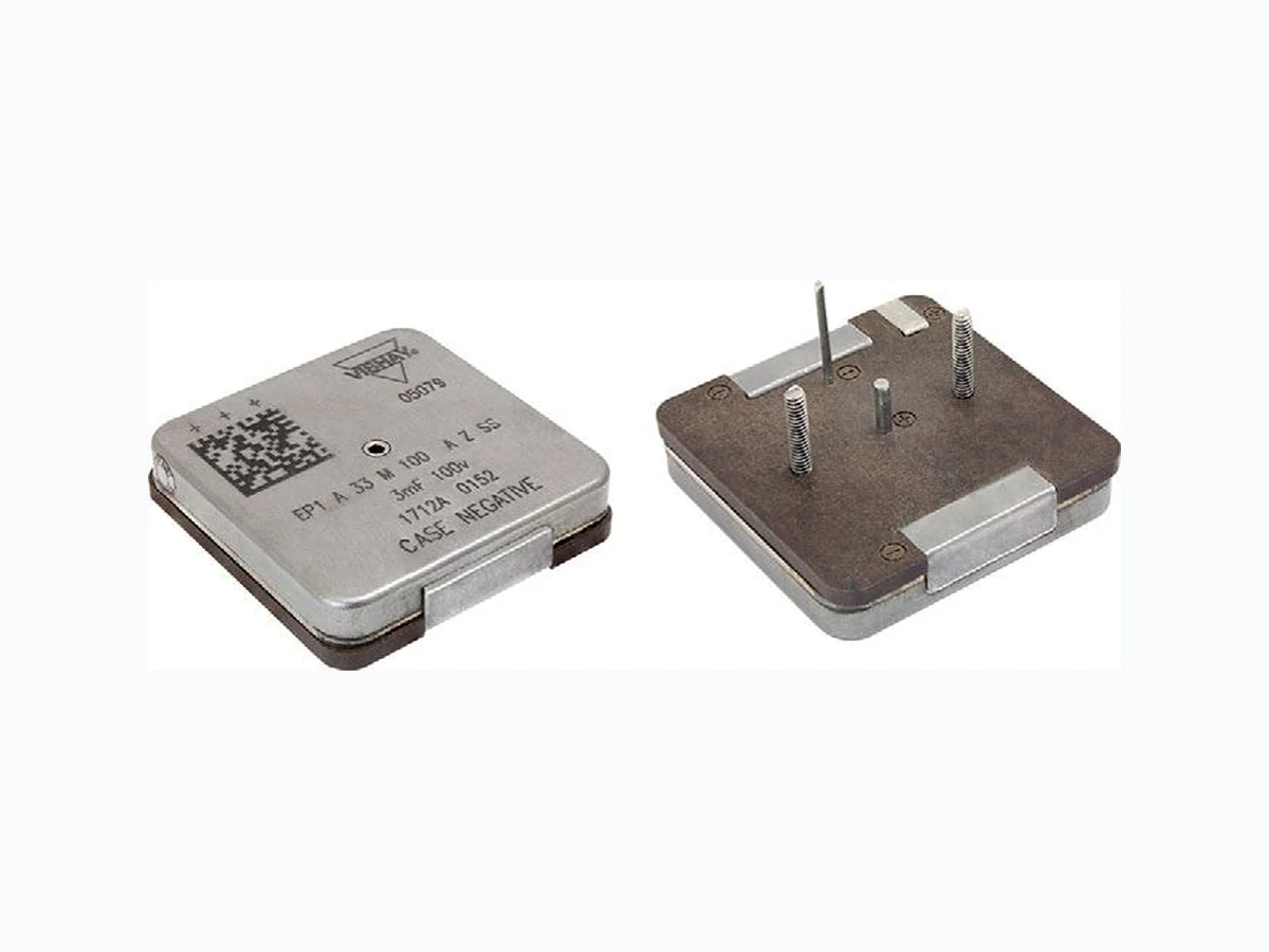
EP1 VISHAY
Document overview
- Manufacturer or author: Provided By www.digicamel.com(FREE DATASHEET DOWNLOAD SITE)
- PDF pages: 8
Technical content
www.vishay.com Vishay Revision: 23-Mar-2021 1 Document Number: 42107 For technical questions, contact: tantalum@vishay.com THIS DOCUMENT IS SUBJECT TO CHANGE WITHOUT NOTICE. THE PRODUCTS DESCRIBED HEREIN AND THIS DOCUMENT ARE SUBJECT TO SPECIFIC DISCLAIMERS, SET FORTH AT www.vishay.com/doc?91000 Wet Tantalum Capacitors, High Energy, Ultra High Capacitance, -55 °C to +125 °C Operation LINKS TO ADDITIONAL RESOURCES
FEATURES
- High energy, very high capacitance design
- All tantalum, hermetically sealed case
- Utilizes Vishay proven SuperTan ® technology
- P a t e n t p e n d i n g
- 2 terminations options: SMD and radial
- Material categorization: fo r definitions of compliance please see www.vishay.com/doc?99912 Note * This datasheet provides information about parts that are RoHS-compliant and / or parts that are non RoHS-compliant. For example, parts with lead (Pb) terminations are not RoHS-compliant. Please see the information / tables in this datasheet for details
APPLICATIONS
- Industrial
- Avionics / military / space
- Ideal for capacitor banks PERFORMANCE CHARACTERISTICS Operating Temperature: -55 °C to +85 °C (to +125 °C with voltage derating) Capacitance Tolerance: at 120 Hz, +25 °C ± 20 % standard ± 10 % available as special Contact marketing for availability of 10 % tolerance DC Leakage Current (DCL Max.): at +25 °C: leakage current shall not exceed the values listed in the Standard Ratings tables. Life Test: capacitors are capable of withstanding a 2000 h life test at a temperature of +85 °C at the applicable rated DC working voltage. Note (1) Contact marketing for availability of 10 % tolerance 333DDD3 D 3D Models Available Available
ORDERING INFORMATION
TYPE CASE CAPACITANCE CAPACITANCE DC VOLTAGE TERMINATION RELIABILITY TEMPERATURE ESR MOUNTING CODE TOLERANCE RATING CODE LEVEL STUD AT +85 °C LENGTH See Dimensions sheets This is expressed in microfarads. The first two digits are the significant figures. The third is the number of zeros to follow. K = 10 % (1) M = 20 % This is expressed in V. To complete the three-digit block, zeros precede the voltage rating. A decimal point is indicated by an “R” (6R3 = 6.3 V) See termination / mounting options in the Dimensions sheets. Z = non-ER S = standard (-55 °C to +85 °C) S = standard Blank = not applicable A = 0.21" B = 0.27" C = 0.40" D = 0.15" E = 0.18" F = 0.35"
www.vishay.com Vishay Revision: 23-Mar-2021 2 Document Number: 42107 For technical questions, contact: tantalum@vishay.com THIS DOCUMENT IS SUBJECT TO CHANGE WITHOUT NOTICE. THE PRODUCTS DESCRIBED HEREIN AND THIS DOCUMENT ARE SUBJECT TO SPECIFIC DISCLAIMERS, SET FORTH AT www.vishay.com/doc?91000 DIMENSIONS - RADIAL TERMINATION in inches CASE SIZE H TERMINATION CODE TERMINATION / MOUNTING OPTION A 0.312 A 100 % tin (RoHS compliant) radialB 0.450 C 0.596 B Tin / lead radial D 0.755 H 0.230 ± 0.020 0.400 ± 0.010 1.455 ± 0.010 R0.130 1.400 ± 0.010 Ø 0.064 ± 0.003 positive lead (see termination code) Ø 0.040 ± 0.003 negative lead (see termination code) 0.700 0.722 0.500 MIN. Case negative conductor Negative conductor Negative conductor Insulator base Positive conductor
www.vishay.com Vishay Revision: 23-Mar-2021 3 Document Number: 42107 For technical questions, contact: tantalum@vishay.com THIS DOCUMENT IS SUBJECT TO CHANGE WITHOUT NOTICE. THE PRODUCTS DESCRIBED HEREIN AND THIS DOCUMENT ARE SUBJECT TO SPECIFIC DISCLAIMERS, SET FORTH AT www.vishay.com/doc?91000 DIMENSIONS - RADIAL TERMINATION WITH STUDS in inches CASE SIZE H TERMINATION CODE TERMINATION / MOUNTING OPTION A 0.312 C 100 % tin (RoHS compliant) radial w/stud mountB 0.450 C 0.596 D Tin / lead radial w/stud mount D 0.755 SL STUD LENGTH CODE SL DIM A0 . 2 1 B0 . 2 7 C0 . 4 0 D0 . 1 5 E0 . 1 8 F0 . 3 5 1.400 ± 0.010 0.700 0.722 1.455 ± 0.010 0.400 ± 0.010 0.400 0.800 ± 0.005 H 0.500 MIN. Negative conductor Negative conductorPositive conductor Insulator base 0.230 ± 0.020 SL code ± 0.010 Ø 0.064 ± 0.003 Positive lead (see termination code) Ø 0.040 ± 0.003 Negative lead (see termination code) 2-56 threaded stud (2 plcs) material 316 SS (non-conductor)
www.vishay.com Vishay Revision: 23-Mar-2021 4 Document Number: 42107 For technical questions, contact: tantalum@vishay.com THIS DOCUMENT IS SUBJECT TO CHANGE WITHOUT NOTICE. THE PRODUCTS DESCRIBED HEREIN AND THIS DOCUMENT ARE SUBJECT TO SPECIFIC DISCLAIMERS, SET FORTH AT www.vishay.com/doc?91000 DIMENSIONS - SMD TERMINATION in inches CASE SIZE H TERMINATION CODE TERMINATION / MOUNTING OPTION A 0.312 E 100 % tin (RoHS compliant) SMDB 0.450 C 0.596 F Tin / lead SMD D 0.755 1.400 ± 0.010 0.625 TYP. 0.169 TYP. 0.313 TYP. 1.455 ± 0.010 0.265 0.125 0.128 0.006 MIN. Pads above plastic base (TYP.) Insulator base Negative pad (2) plcs material = nickel (see termination code) Recommended Solder Pad Layout Keep out zone 0.165 0.763 0.438 1.450 0.433 0.513 TYP. 0.227 TYP. 0.665 TYP. 0.338 TYP. 1.450 Positive pad material = nickel (see termination code) Case negative
www.vishay.com Vishay Revision: 23-Mar-2021 5 Document Number: 42107 For technical questions, contact: tantalum@vishay.com THIS DOCUMENT IS SUBJECT TO CHANGE WITHOUT NOTICE. THE PRODUCTS DESCRIBED HEREIN AND THIS DOCUMENT ARE SUBJECT TO SPECIFIC DISCLAIMERS, SET FORTH AT www.vishay.com/doc?91000 DIMENSIONS - SMD TERMINATION WITH STUDS in inches CASE SIZE H TERMINATION CODE TERMINATION / MOUNTING OPTION A 0.312 G 100 % tin (RoHS compliant) SMD w/stud mountB 0.450 C 0.596 H Tin / lead SMD w/stud mount D 0.755 SL STUD LENGTH CODE SL DIM A0 . 2 1 B0 . 2 7 C0 . 4 0 D0 . 1 5 E0 . 1 8 F0 . 3 5 0.165 0.763 0.513 TYP. Negative pad (see termination code) Positive pad (see termination code) Case negative 1.400 ± 0.010 0.700 SL code ± 0.010 H 0.722 1.455 ± 0.010 0.400 0.800 ± 0.005 2-56 threaded stud (2 plcs) material 316 SS (non-conductor) Negative pad (see termination code) Insulator base Keep out zone Ø 0.086 Clearance for 2-56 thread (2 plcs) 0.438 0.433 1.450 0.800 0.665 TYP. 0.227 TYP. 0.338 TYP. 1.450
www.vishay.com Vishay Revision: 23-Mar-2021 6 Document Number: 42107 For technical questions, contact: tantalum@vishay.com THIS DOCUMENT IS SUBJECT TO CHANGE WITHOUT NOTICE. THE PRODUCTS DESCRIBED HEREIN AND THIS DOCUMENT ARE SUBJECT TO SPECIFIC DISCLAIMERS, SET FORTH AT www.vishay.com/doc?91000 STANDARD RATINGS CAPACITANCE (μF) CASE CODE PART NUMBER MAX. ESR AT +25 °C, 1 kHz (Ω) MAX. DCL AT +25 °C (μA) MAX. DCL AT +85 °C (mA) WEIGHT (g) 25 VDC AT +85 °C; 15 VDC AT +125 °C, SURGE VOLTAGE = 27.5 VDC 30 000 A EP1A303(1)025(2)(3)(4)(5) 0.030 150 1.5 63 35 VDC AT +85 °C; 21 VDC AT +125 °C, SURGE VOLTAGE = 38.5 VDC 22 000 A EP1A223(1)035(2)(3)(4)(5) 0.040 150 1.5 63 36 000 B 40 000 B (2) EP1B403(1)035(2)(3)(4)(5) 0.020 250 2 100 47 800 C (1) EP1C473(1)035(2)(3)(4)(5) 0.015 350 3 120 58 000 C (2) EP1C583(1)035(2)(3)(4)(5) 0.015 350 3 120
50 VDC AT +85 °C; 30 VDC AT +125 °C, SURGE VOLTAGE = 55 VDC
12 000 A EP1A123(1)050(2)(3)(4)(5) 0.050 100 1.0 63 13 000 A 17 500 B (1) EP1B173(1)050(2)(3)(4)(5) 0.025 100 1.5 100 23 400 C (1) EP1C233(1)050(2)(3)(4)(5) 0.017 200 2.5 120 24 000 B (2) EP1B243(1)050(2)(3)(4)(5) 0.025 100 1.5 100 34 000 C (2) EP1C343(1)050(2)(3)(4)(5) 0.017 200 2.5 120
63 VDC AT +85 °C; 38 VDC AT +125 °C, SURGE VOLTAGE = 69 VDC
6000 A EP1A602(1)063(2)(3)(4)(5) 0.050 100 1.0 63 9400 B EP1B942(1)063(2)(3)(4)(5) 0.025 100 1.5 86 11 000 B EP1B113(1)063(2)(3)(4)(5) 0.025 150 1.5 100 12 000 B 14 500 C EP1C143(1)063(2)(3)(4)(5) 0.017 250 2.5 120 18 000 C
80 VDC AT +85 °C; 48 VDC AT +125 °C, SURGE VOLTAGE = 88 VDC
4000 A EP1A402(1)080(2)(3)(4)(5) 0.055 100 1.0 63 6800 B 9000 C EP1C902(1)080(2)(3)(4)(5) 0.025 250 2.5 120 12 000 C (2) EP1C123(1)080(2)(3)(4)(5) 0.025 250 2.5 120
100 VDC AT +85 °C; 60 VDC AT +125 °C, SURGE VOLTAGE = 110 VDC
3000 A EP1A302(1)100(2)(3)(4)(5) 0.065 100 1.0 63 4400 B EP1B442(1)100(2)(3)(4)(5) 0.035 150 1.5 100 5800 B 125 VDC AT +85 °C; 75 VDC AT +125 °C, SURGE VOLTAGE = 137.5 VDC 1900 A EP1A192(1)125(2)(3)(4)(5) 0.100 100 1.0 63 2000 A Notes
- Part number definitions: (1) Standard capacitance tolerance is 20 % or “M“. Contact marketing for availability of 10 % or “K“ (2) Standard termination is “B” radial tin / lead. RoHS compliant or radial 100 % tin is available as “A“ (3) Standard reliability is “Z” or non-established reliability (4) Standard temperature range is “S” or -55 °C to +85 °C or +125 °C with voltage derating (5) Standard ESR is “S“ (1) Preliminary rating, specification subject to change. Contact marketing for availability (2) Requires export license for shipments outside the US. Contact marketing for availability
www.vishay.com Vishay Revision: 23-Mar-2021 7 Document Number: 42107 For technical questions, contact: tantalum@vishay.com THIS DOCUMENT IS SUBJECT TO CHANGE WITHOUT NOTICE. THE PRODUCTS DESCRIBED HEREIN AND THIS DOCUMENT ARE SUBJECT TO SPECIFIC DISCLAIMERS, SET FORTH AT www.vishay.com/doc?91000 PERFORMANCE CHARACTERISTICS OF HIGH ENERGY CAPACITORS Note
- For surface-mount solder attachme nt refer to application note 42110: www.vishay.com/doc?42110 ELECTRICAL PERFORMANCE CHARACTERISTICS ITEM PERFORMANCE CHARACTERISTICS Operating temperature range Per MIL-PRF-39006. -55 °C to +85 °C or +125 °C with voltage derating (see Standard Ratings table) Storage temperature range Per MIL-PRF-39006. -62 °C to +130 °C Capacitor tolerance ± 20 % ± 10 % at 120 Hz ESR Limits per Standard Ratings table DC leakage current (DCL max.) At 25 °C the leakage current sh all not exceed values listed in the Standard Rating table. Reverse voltage There shall be no continuous reverse voltage. Transient reverse voltage surges are acceptable under the following conditions: a) The peak reverse voltage is equal to or less than 1.0 V and the product of the peak current times the duration of the reverse transient is 0.05 A or less b) The repetition rate of the revers e voltage surges is less than 10 Hz Surge voltage The test shall be at 1000 cycles at 110 % of rated voltage at 85 °C. A cycle consists of a 30 s charge and a 330 s discharge through 1000 Ω resistor. Life test 2000 h at +85 °C ENVIRONMENTAL CHARACTERISTICS ITEM TEST AND CONDITIONS COMMENTS Hermeticity MIL-STD-202, method 112 C/IIIa The capacitor shall be hermetically sealed such that the case does not leak electrolyte or vent any gas when exposed to a vacuum. Moisture resistance MIL-STD-202, method 106 6 V polarity Altitude MIL-STD-202, method 105 C, test condition D 100 000 feet test Fungus MIL-PRF-39006 The capacitor materials shall not support fungus growth and shall not be a nutrient to fungus. MECHANICAL PERFORMANCE CHARACTERISTICS ITEM TEST AND CONDITIONS COMMENTS Thermal shock MIL-STD-202, method 107 G Test condition A Shock MIL-STD-202, method 213 B test condition G 11 ms, 50 g Vibration - high frequency MIL-STD-202, method 204 D test condition D 12 sweeps/axis, 20 g peak Vibration - random MIL-STD-202, method 214 A test condition II, letter E 1.5 h/axis, 19.64 g Resistance to solder heat MIL-STD-202, method 210 F, test conditions A and B Solderability MIL-STD-202, method 208 Terminal strength MIL-STD-202, method 211 A The capacitor terminals must withstand a 5 pound pull test for 5 s to 10 s. The capacitor must not be visi bly damaged and the electrical characteristics must not be affected. Part markings MIL-STD-202, method 215 J The capacitor shall be permanently and legibly marked on the circumference of the case. The markings shall be resistant to solvents. Weight (mass) See Standard Ratings table Seal MIL-PRF-39006 MSL J-STD-033 Not applicable Packaging MIL-PRF-39006 All uni ts are shipped in individual bulk packages. Stud mounting Tighten nuts only ½ to ¾ turn beyond point of initial contact, equivalent to 24 to 28 maximum inch-ounces torq ue. Maximum pre-load tension ~ 15 pounds. Lock washers are not recommended; use an adhesive lock nut conforming to MIL-S-22473E, grade A - red
www.vishay.com Vishay Revision: 01-Jan-2021 1 Document Number: 91000 Disclaimer ALL PRODUCT, PRODUCT SPECIFICATIONS AND DATA AR E SUBJECT TO CHANGE WITH OUT NOTICE TO IMPROVE RELIABILITY, FUNCTION OR DESIGN OR OTHERWISE. Vishay Intertechnology, Inc., its affiliates, agents, and employee s, and all persons acting on it s or their behalf (collectivel y, “Vishay”), disclaim any and all liability for any errors, inaccuracies or incompleteness contained in any datasheet or in any other disclosure relating to any product. Vishay makes no warranty, representation or guarantee regarding the suitability of the products for any particular purpose or the continuing production of any product. To the maximum extent permitted by applicable law, Vishay disclaims (i) any and all liability arising out of the application or use of any product , (ii) any and all liability, including without limitation specia l, consequential or incidental damages, and (iii) any and all implied warranties, incl uding warranties of fitness for particular purpose, non-infringement and merchantability. Statements regarding the suitability of products for certain types of applicatio ns are based on Vishay’s knowledge of typical requirements that are often placed on Vishay products in generic applications. Such statements are not binding statements about the suitability of products for a particular applic ation. It is the customer’s responsibility to validate tha t a particular product with the prope rties described in the product sp ecification is suitable for use in a particular application. Parameters provided in datasheets and / or specifications may vary in different ap plications and performance may vary over time. All operating parameters, including typical parameters, must be validated for each customer application by the customer’s technical experts. Product specifications do not expand or otherwise modify Vishay’s term s and conditions of purchase, including but not limited to the warranty expressed therein. Except as expressly indicated in writing, Vishay products are not designed for use in medical, life-saving, or life-sustaining applications or for any other application in which the failure of the Vishay product could result in personal injury or death. Customers using or selling Vishay product s not expressly indicated for use in such applications do so at their own risk. Please contact authorized Vishay personnel to obtain writ ten terms and conditions rega rding products designed for such applications. No license, express or implied, by estoppel or otherwise, to any intellectual property rights is gr anted by this document or by any conduct of Vishay. Product names and markings noted herein may be trademarks of their respective owners. © 2021 VISHAY INTERTECHNOLOGY, INC. ALL RIGHTS RESERVED