
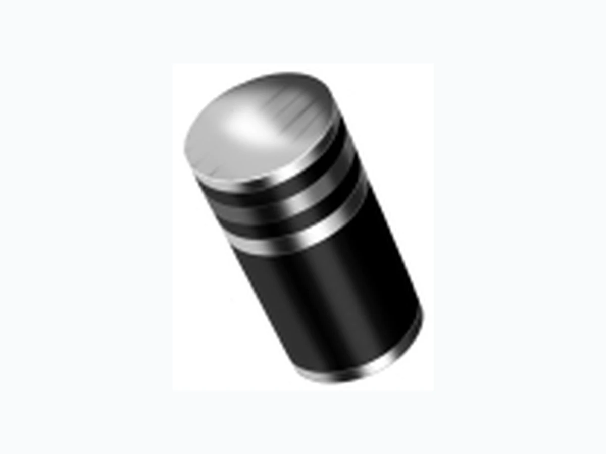
BYM07-50 VISHAY
Document overview
- Manufacturer or author: Provided By www.digicamel.com(free datasheet download site)
- PDF pages: 2
Technical content
Features
Plastic package has Underwriters Laboratories Flammability Classification 94V-0 Capable of meeting environmental standards of MIL-S-19500 High temperature metallurgically bonded construction Cavity-free glass passivated junction Fast switching for high efficiency High temperature soldering guaranteed: 450°C/5 seconds at terminals. Complete device submersible temperature of 260°C for 10 seconds in solder bath Mechanical Data Case: JEDEC DO-213AA, molded plastic over glass body Terminals:Plated terminals, solderable per MIL-STD-750, Method 2026 Polarity:Two bands indicate cathode end – 1st band denotes device type and 2nd band denotes repetitive peak reverse voltage rating Mounting Position:Any Weight:0.0014 oz., 0.036 g Dimensions in inches and (millimeters) *Glass-plastic encapsulation is covered by Patent No. 3,996,602 and brazed-lead assembly to Patent No. 3,930,306
BYM07-50 thru BYM07-400, EGL34A thru EGL34G Vishay Semiconductors formerly General Semiconductor www.vishay.com Document Number 88580 2 03-Apr-03 Ratings and Characteristic Curves(TA = 25°C unless otherwise noted) 2.0 4.0 6.0 8.0 1 100 10 Fig. 2 – Maximum Non-Repetitive Peak Forward Surge Current Peak Forward Surge Current (A) Number of Cycles at 60 HZ 0 25 50 75 100 125 150 175 Fig. 1 – Forward Current Derating Curve Average Forward Rectified Current (A) Terminal Temperature (°C) Instantaneous Forward Voltage (V) Fig. 3 – Typical Instantaneous Forward Characteristics Fig. 4 – Typical Reverse Characteristics Instantaneous Reverse Leakage Current (µA) Percent of Rated Peak Reverse Voltage (%) 0.3 0.5 0.4 0.2 0.1 Resistive or Inductive Load Instantaneous Forward Current (A) Reverse Voltage (V) Junction Capacitance (pF) Fig. 5 – Typical Junction Capacitance TJ = TJ max. 8.3ms Single Half Sine-Wave (JEDEC Method) t, Pulse Duration (sec.) Transient Thermal Impedance (°C/W) 0.01 0.1 1 10 100 100 Fig. 6 – Typical Transient Thermal Impedance 0.1 0.1 0.01 0 20 40 60 80 100 0.001 0.01 0.1 100 TJ = 150°C TJ = 125°C TJ = 25°C TJ = 75°C 0.1 1 10 100 TJ = 25°C f = 1.0 MHZ Vsig = 50mVp-p Pulse Width = 300µs 1% Duty Cycle EGL34A – EGL34D EGL34F & EGL34G TJ = 25°C TJ = 150°C