
 Download PDF
IRPLHID2A IRF
Document overview
- PDF pages: 30
Technical content
Page 1
IRPLHID2A
HID Ballast for 70W Lamp Using the IRS2573D
Table of Contents
Page
- Features ........................................................................................... 2 2. Overview .......................................................................................... 3 3. Electrical Characteristic .................................................................... 4 4. Circuit Schematic ............................................................................. 5 5. Functional Description ...................................................................... 7 6. Fault Conditions ............................................................................. 15 7. Dimensioning ................................................................................. 18
- PCB Layout Considerations ........................................................... 23 9. Bill of Materials ............................................................................... 24 10. IRPLHID2A PCB Layout ............................................................... 26 11. Inductor Specifications ................................................................. 28
- 1 -
Page 2
1. Features
Drives 1 x 70W HID lamp Input voltage range: 185-265 VAC High Power Factor / Low Total Harmonic Distortion Controlled ignition Low frequency square wave operation Lamp power and current control Open circuit and no-lamp protection Short circuit and lamp failure to warm-up protection Lamp end-of-life shutdown IRS2573DSPbF HID Ballast Control IC
- 2 -
Page 3
2. Overview
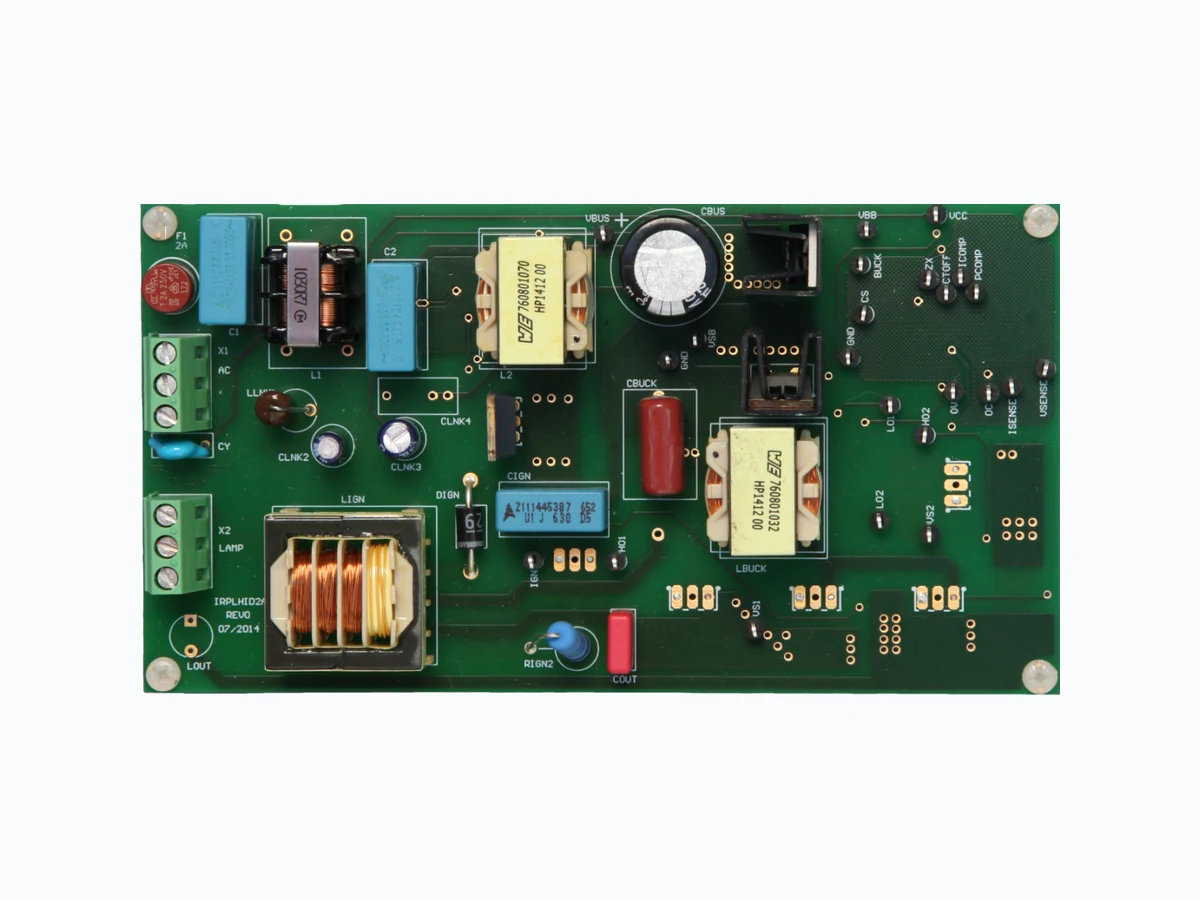
The IRPLHID2A reference design kit consists of a complete ballast solution for a 70W HID lamp. The design contains an EMI filter, low voltage power supply, active power factor correction and a ballast control circuit using the IRS2573D. This demo board is intended to help with the evaluation of the IRS2573D HID ballast control IC, demonstrate PCB layout techniques and serve as an aid in the development of production ballasts using the IRS2573D.
Active PFC
Buck
EMI Filter
Rectifier
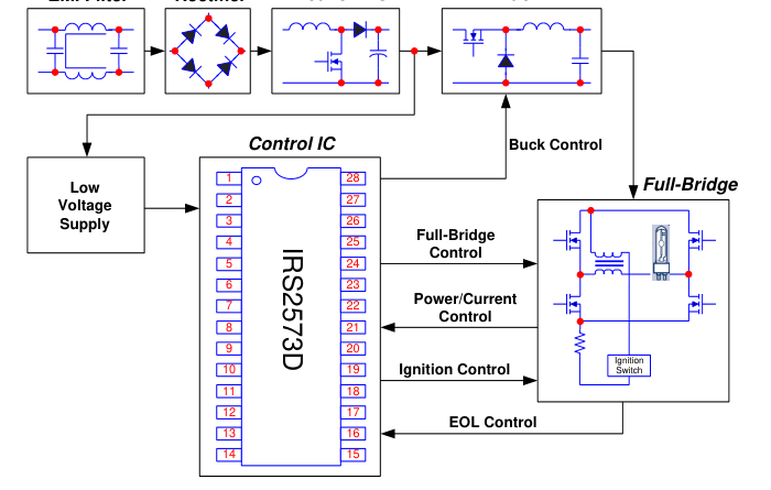
Figure 2.1: IRPLHID2A Block Diagram
- 3 -
Page 4
3. Electrical Characteristic
| Parameter | Units | Value |
|---|---|---|
| Lamp Power | [W] | 70 |
| Input Power | [W] | 75 |
| Input Voltage | [VACrms] | 220 |
| Input Current | [mArms] | 338 |
| Lamp Running Voltage | [Vpp] | 160 |
| Lamp Running Current | [App] | 1.6 |
| Output Frequency | [Hz] | 149 |
| Power Factor | 0.98 at 230 VAC | |
| Total Harmonic Distortion | [%] | <10 at 230 VAC |
| Input AC Voltage Range | [VACrms] | 185 - 265 |
TABLE 3.1: Ballast Parameters.
- 4 -
Page 5
4. Circuit Schematic 1
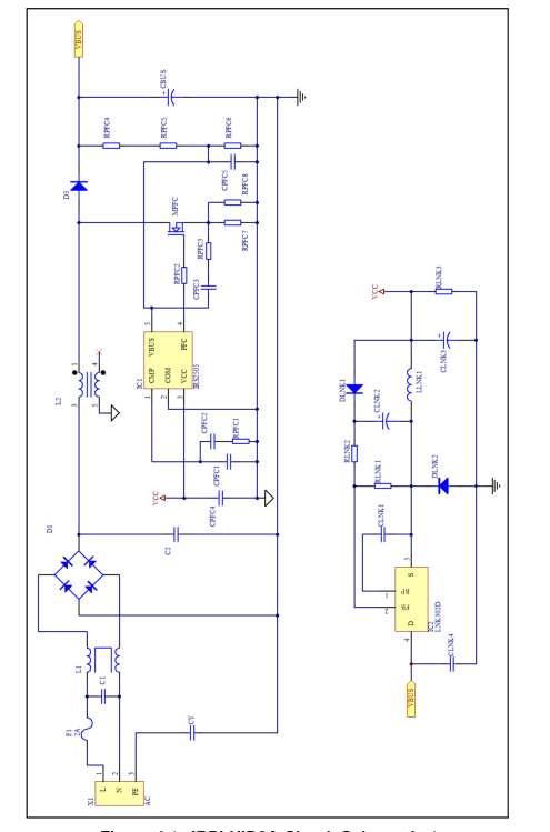
Figure 4.1: IRPLHID2A Circuit Schematic 1
- 5 -
Page 6
Circuit Schematic 2
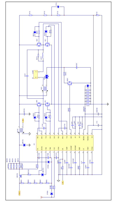
Figure 4.2: IRPLHID2A Circuit Schematic 2
- 6 -
Page 7
5. Functional Description
HID lamps have unique electrical characteristics, and require a careful control method. Specifically, they require a high voltage for ignition, typically 3 kV to 4 kV, current limitation during warm-up, and constant power control during running. It is important to tightly regulate lamp power with respect to lamp voltage to minimize lamp-to-lamp color and brightness variations. Also, HID lamps should be driven using an AC-voltage to avoid mercury migration, and at a low frequency, typically less than 200 Hz, to prevent lamp damage or explosion due to acoustic resonance. All of these requirements are integrated in the IRS2573D.
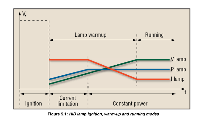
The IRS2573D is a fully-integrated, fully-protected 600V HID control IC designed to drive all types of HID lamps. Internal circuitry provides control for ignition, warm-up, running and fault operating modes. The IRS2573D features include ignition timing control, constant lamp power control, current limitation control, programmable full-bridge running frequency, programmable over and under-voltage protection and programmable overcurrent protection. Advanced protection features such as failure of a lamp to ignite, open load, short-circuit and a programmable fault counter have also been included in the design.
- 7 -
Page 8
5.1 IRS2573D State and Timing Diagram
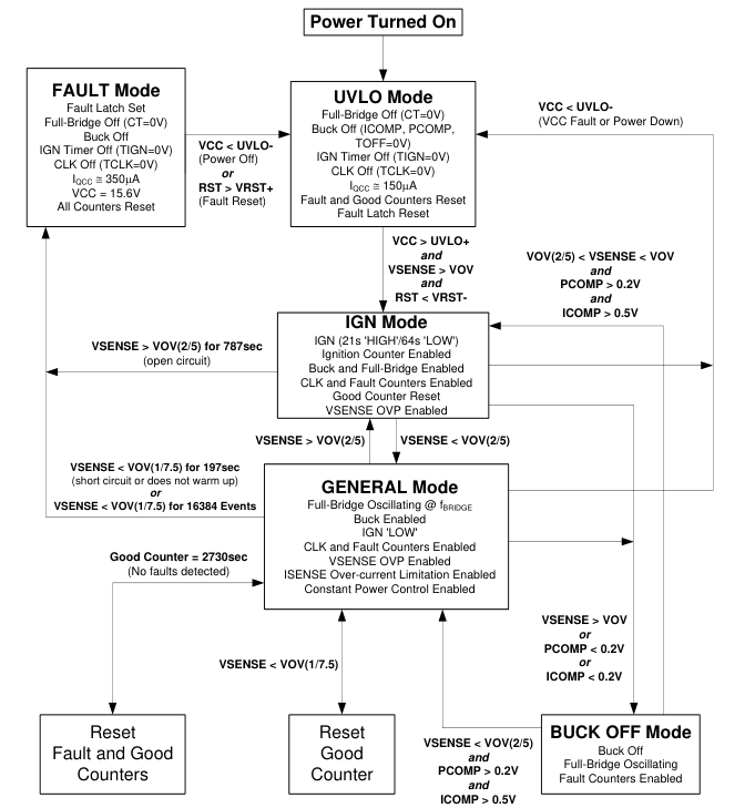
Figure 5.2: IRS2573D state and timing diagram
5.2 Under-voltage Lockout (UVLO) Mode
The under-voltage lockout mode (UVLO) is defined as the state the IC is in when VCC is
below the turn-on threshold of the IC. The IC is designed to maintain an ultra-low supply
current during UVLO mode of 150uA, and to guarantee the IC is fully functional before
- 8 -
Page 9
the buck high-side and full-bridge high and low-side output drivers are activated. The low voltage power supply is realized with buck converter circuit utilizing the Link Switch LNK302D (Figure 4.1). Once the voltage on VCC reaches the start-up threshold (UVLO+), voltage on VSENSE pin is above VOV threshold and the voltage on RST pin is less than 1.5V, the IC turns on and the full-bridge oscillator (CT) and gate driver outputs (HO1, LO1, HO2 and LO2) begin to oscillate. During UVLO mode, the full-bridge and buck are off, the ignition timer and clock are off, the fault and good counters are reset, and the fault latch is reset.
5.3 Ignition Mode
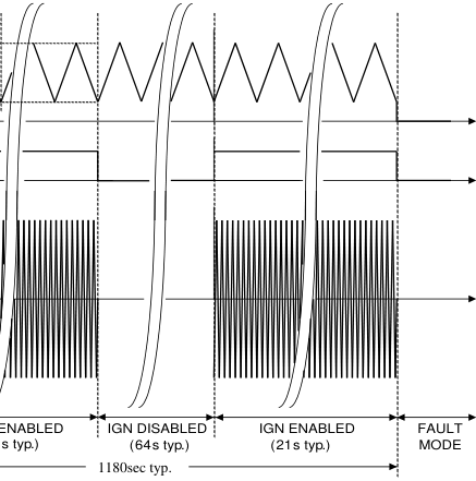
The ignition timer is enabled when the IC first enters IGN Mode. The ignition timer frequency is programmed with the external capacitor at the TIGN pin. CTIGN charges up and down linearly through internal sink and source currents between a fixed voltage window of 2V and 4V (Figure 5.3). This sets up an internal clock (666ms typical) that is divided out 128 times and then used to turn the ignition gate driver output (IGN pin) on and off for a given on and off-time (21sec ‘high’/64sec ‘low’ typical). A logic ‘high’ at the IGN pin will turn the external ignition MOSFET (MIGN) on and enable the external sidaccontrolled pulse ignition circuit.
666ms
typ.
4V TIGN
2V
IGN
VLAMP
0V
(21s typ.)
Figure 5.3: Ignition Timer Timing Diagram
During the ignition phase, the lamp is an open circuit and the buck output voltage is limited to a maximum value. The ignition circuit comprises of a diac (DIGN), transformer
- 9 -
Page 10
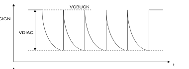
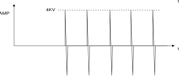
(LIGN), capacitor (CIGN), resistor (RIGN2) and switch (MIGN). When the IC turns on the switch MIGN, capacitor CIGN discharges through resistor RIGN2. When the voltage across DIGN reaches the diac threshold voltage (Figure 5.4), DIGN turns on and a current pulse flows from the buck output, through the primary winding of LIGN and into capacitor CIGN. This arrangement generates a high-voltage pulse on the secondary to ignite the lamp. The capacitor CIGN charges up until the diac turns off, and CIGN then discharges down through resistor RIGN until the diac voltage again reaches the device’s threshold and another ignition pulse occurs.
VGATE:MIGN
VLAMP
Figure 5.4: Ignition circuit timing diagram
The ignition circuit will continuously try to ignite the HID lamp for 21sec ‘on’ and 64sec ‘off’ until the lamp ignites. If the lamp does not ignite after 1180sec then the IC will enter Fault Mode and latch off. If the lamp ignites successfully, the voltage at the VSENSE pin will fall below VOV(2/5) due to the low impedance of the lamp and the ignition timer will be disabled (logic ‘low’ at the IGN pin).
5.4 General Mode
During General Mode, the IC reacts to the different load conditions (open-circuit, shortcircuit, lamp warm-up, constant power running, under-voltage lamp faults, transient under-voltage lamp faults, over-voltage lamp faults, lamp non-strike, etc.) by turning the buck circuit on or off, adjusting the buck circuit on-time, or counting the occurrence of the different fault conditions and turning the complete IC off. The IC senses the different load conditions at the VSENSE and ISENSE pins, compares the voltages at these pins against the programmed thresholds at the OV and OC pins, and determines the correct operating mode of the IC (see State Diagram).
5.5 Full-Bridge Control
The IC includes a complete high and low-side full-bridge driver necessary for driving the
- 10 -
Page 11
HID lamp with an AC square-wave voltage. The full-bridge begins oscillating at the programmed frequency immediately when the IC comes out of UVLO Mode and turns on. The full-bridge is typically driven at a low frequency to prevent acoustic resonances from damaging the lamp. The full-bridge frequency is programmed with the external capacitor at the CT pin. CT charges up and down linearly through internal sink and source currents between a fixed voltage window of 2V and 4V. CT reaching 4V initiates the toggling of LO1/HO1, and LO2/HO2 respectively (see Figure 5.5). The dead-time is fixed internally at 1.0us typical. During the dead-time, all full-bridge MOSFETs are off
and the mid-points of each half-bridge are floating or unbiased. Should an external transient occur during the dead-time due to an ignition voltage pulse, each half-bridge mid-point (VS1 and VS2 pins) can slew high or low very quickly and exceed the dv/dt rating of the IC. To prevent this, internal logic guarantees that the IGN pin is set to a logic ‘low’ during the dead-time. No ignition pulses can occur until the dead-time has ended and the appropriate full-bridge MOSFETs are turned on. This will guarantee that the mid-points are biased to the output voltage of the buck or COM before an ignition pulse occurs. The full-bridge stops oscillating only when the IC enters Fault Mode or
UVLO Mode.
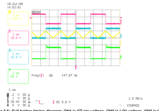
Figure 5.5: Full-bridge timing diagram: CH1 is CT pin voltage, CH2 is LO1 voltage, CH3 is LO2
voltage and CH4 is VS1 pin voltage
5.5 Buck Control
The buck control circuit operates in critical-conduction mode or continuous-conduction mode depending on the off-time of the buck output or the peak current flowing through the buck MOSFET (MBUCK). During normal lamp running conditions, the voltage across the buck current sensing resistor, as measured by the CS pin, is below the internal over-current threshold (1.2V typical). The buck on-time is defined by the time it takes for the internal on-time capacitor to charge up to the voltage level on the PCOMP pin or ICOMP pin, whichever is lower. During the on-time, the current in the buck
- 11 -
Page 12
inductor charges up to a peak level, depending on the inductance value, and the secondary winding output of the buck inductor is at some negative voltage level, depending on the ratio between the primary and secondary windings. The secondary winding output is measured by the ZX pin, which clamps the negative voltage to a diode drop below COM using the internal ESD diode, and limits the resulting negative current flowing out of the pin with an external resistor, RZX. When the voltage on the internal on-time capacitor exceeds the voltage on the PCOMP pin or ICOMP pin, the on-time has ended and the buck output turns off.
The secondary winding output of the buck inductor transitions to some positive voltage level, depending on the ratio between the primary and secondary windings, and causes the ZX pin to exceed the internal 2V threshold. The current in the buck inductor begins to discharge into the lamp full-bridge output stage. When the inductor current reaches zero, the ZX pin decreases back below the 2V threshold. This causes the internal logic of the buck control to start the on-time cycle again. This mode of operation is known as critical-conduction mode because the buck MOSFET is turned on each cycle when the inductor current discharges to zero. The on-time is programmed by the voltage level on
the PCOMP pin, and the off-time is determined by the time it takes for the inductor current to discharge to zero, as measured by a negative-going edge on the ZX pin. The resulting shape of the current in the inductor is triangular with a peak value determined by the inductance value and on-time setting.
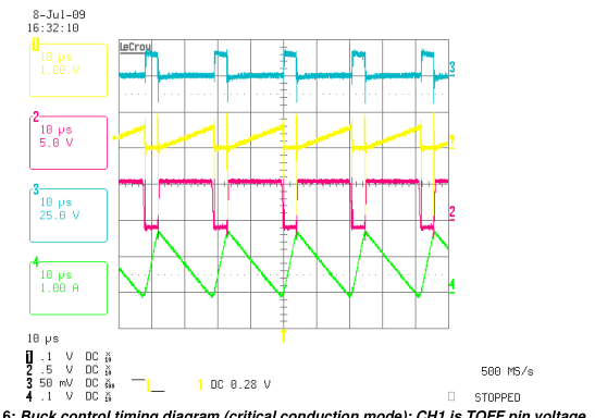
Figure 5.6: Buck control timing diagram (critical conduction mode): CH1 is TOFF pin voltage, CH2 is ZX pin voltage, CH3 is Buck output voltage and CH4 is current through buck inductor LBUCK
During lamp warm-up or a short-circuit condition at the output, the inductor current will charge up to an excessive level that can saturate the inductor or damage the buck MOSFET. To prevent this condition, the buck current sensing resistor (RBCS) is set such that the voltage at the CS pin exceeds the internal over-current threshold (1.2V typical) before the inductor saturates. Should the CS pin exceed 1.2V before the internal
- 12 -
Page 13
on-time capacitor reaches the voltage level on the PCOMP pin or ICOMP pin, the on- time will end and the buck output will turn off. The off-time is determined by a negativegoing edge on the ZX pin, or, if the maximum off time is reached as programmed by the time it takes for the CTOFF on the TOFF pin to charge up to an internal threshold of 2V. If the maximum off-time is reached before the inductor current discharges to zero, then the inductor will begin charging again from some value above zero. This mode of operation is known as continuous-conduction mode and results in a continuous DC current in the inductor with a ripple bounded above by the over-current threshold and
below by the maximum off time setting (see Figure 5.7). Continuous-conduction mode also allows for a higher average current to flow through the buck inductor before saturation occurs than with critical-conduction mode.
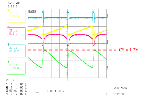
Figure 5.7: Buck control timing diagram (continuous conduction mode): CH1 is TOFF pin voltage, CH2 is ZX pin voltage, CH3 is Buck output voltage and CH4 is current through buck inductor LBUCK
5.6 Constant Power Control
During the general mode of operation and after the lamp has ignited, the IC regulates the lamp output power to a constant level. To achieve this, the IC measures the lamp voltage and lamp current at the VSENSE and ISENSE pins, multiplies the voltage and current together using an internal multiplier circuit to calculate power, and regulates the output of the multiplier circuit to a constant reference voltage by increasing or decreasing the buck on-time. If the lamp power is too low then the output of the multiplier will be below the internal reference voltage. The operational trans-conductance amplifier (OTA) will output a sourcing current to the PCOMP pin that will charge up the CPCOMP to a
higher voltage. This will increase the on-time of buck and increase the output current to the lamp for increasing the output power. If the lamp power is too high, then the opposite will occur. The OTA will output a sinking current to the PCOMP pin that will discharge the CPCOMP to a lower voltage. This will decrease the buck on-time and
- 13 -
Page 14
decrease the output current to the lamp for decreasing the output power. The speed of the constant power control loop is set by the value of the CPCOMP at the PCOMP pin that determines how fast the loop will react and adjust the buck on-time over the changing load conditions.
5.7 Current Limitation Control
The constant power control loop will increase or decrease the buck current for maintaining constant power in the lamp load. During lamp warm-up, the lamp voltage can be very low (20V typical) and the constant power loop will attempt to increase the buck current to several amps of current to maintain constant power. This high current can exceed the manufacturer’s maximum current rating for the HID lamp. To prevent this condition, an additional current limitation control loop has been included in the IC Should the voltage at the ISENSE pin exceed the voltage level at the OC pin, another OTA will sink current from the ICOMP pin. When the ICOMP pin voltage decreases
below the PCOMP pin voltage, then the current limitation loop will override the constant power loop and the ICOMP pin will decrease the buck on-time. The lower of the PCOMP or ICOMP pins will override the other and control the buck on-time. When the lamp eventually warms up and the lamp voltage increases to a level where the lamp current is below the maximum allowable limit, then the ICOMP pin voltage will increase above the PCOMP pin voltage, and the PCOMP pin will control the buck on-time again for maintaining constant power.
5.8 Buck OFF Mode
The IC will enter the Buck-OFF Mode if any one of these 3 conditions occur: VSENSE > VOV or PCOMP < 0.2V or ICOMP < 0.2V
When in the Buck-OFF Mode, the IC will go back to General Mode if all of these 3 conditions are valid: VSENSE < VOV (2/5) and PCOMP > 0.2V and ICOMP > 0.5V
The IC will instead go back to Ignition Mode if all of these 3 conditions are valid:
VOV(2/5) < VSENSE < VOV and PCOMP > 0.2V and ICOMP > 0.5V
- 14 -
Page 15
6. Fault Conditions
In case of fault conditions such as open circuit, lamp removal, lamp extinguishes, short circuit, end-of-life and lamp failure to warm-up, the IRS2573D will go into Fault Mode after the fault timer times out. In this mode, the internal fault latch is set, full-bridge and buck are off, ignition and fault timer are off, and the IRS2573D consumes an ultra-low micro-power current. The IRS2573D can be reset with a fault reset (RST > VRST+) or a recycling of VCC below and back above the UVLO thresholds. The fault timer is programmed using the external capacitor CTCLK on the TCLK pin.
6.1 Over-Voltage Fault Counter
The IC includes an over-voltage fault counter at the VSENSE pin. In the IGN Mode, the over-voltage fault counter will count the time during which an over-voltage condition at the output of the buck exists due to an open-circuit condition, lamp extinguishes, lamp removal or end-of-life. Figure 7.1 shows the waveforms when the ballast goes into Fault Mode because of over-voltage fault. When the voltage at the VSENSE pin remains above VOV (2/5) and the over-voltage fault counter times out (1180sec typical, with CTCLK=0.18uF), the IC will enter Fault Mode and shutdown. Before the fault counter times out, the ignition counter is enabled and the IC keeps trying to ignite the lamp for 21
sec ‘on’ and 64 sec ‘off’.
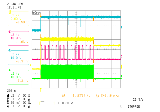
Figure 6.1: Over-voltage fault: CH1 is the VSENSE voltage, CH2 is IGN pin voltage, CH3 is VCC and
CH4 is LO voltage
- 15 -
Page 16
6.2 Under-Voltage Fault Counter
The IC also includes an under-voltage fault counter at the VSENSE pin. Once the lamp has ignited, the lamp voltage will decrease sharply to a very low voltage (20V typical). As the lamp warms up, the lamp voltage will slowly increase until the nominal running voltage is reached (100V typical). If the lamp voltage remains too low for too long, then this is a lamp fault condition and the ballast must shutdown. To detect this, the VSENSE pin includes an under-voltage threshold of VOV(1/7.5). If the voltage at the VSENSE pin remains below VOV(1/7.5) and the under-voltage fault counter times out (295sec typical, with CTCLK=0.18uF), then the lamp is not warming up properly due to a lamp fault
condition (end of life, etc.) and the IC will enter fault mode and shutdown. If the voltage at the VSENSE pin increases above VOV(1/7.5) before the under-voltage counter times out, then the lamp has successfully warmed up and the IC will remain in general mode. Figure 6.2 shows some waveforms when the ballast goes into Fault Mode due to undervoltage fault.
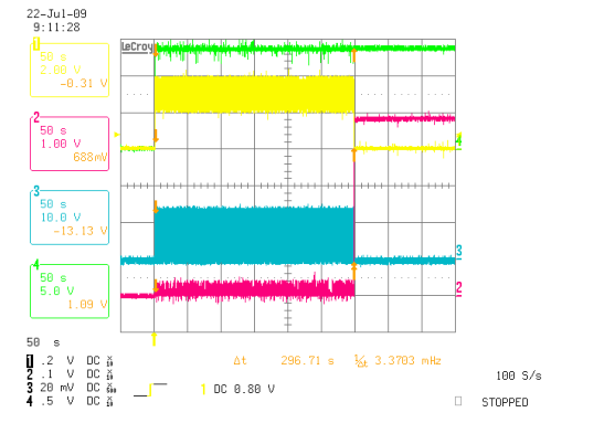
Figure 6.2: Under-voltage fault: CH1 is TCLK pin voltage, CH2 is VSENSE voltage, CH3 is LO voltage
and CH4 is VCC voltage
6.3 Fast Transient Under-Voltage Fault Counter
During normal running conditions, fast transient under-voltage spikes can occur on the lamp voltage due to instabilities in the lamp arc. The resulting transients on the VSENSE pin will cycle below and above the VOV(1/7.5) threshold quickly (<50us). If the number of events of these transients exceeds the maximum number of events of the fault counter (16,384 events typical), then the IC will enter fault mode and shutdown.
- 16 -
Page 17
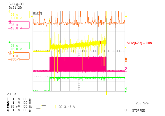
Figure 6.3: Under-voltage fault: CH1 is VSENSE voltage, CH2 is LO voltage, CH4 is VCC voltage and
CHA is zoom of VSENSE voltage
6.4 Good Counter
If no faults are detected for a long period of time (2730sec typical), as measured by the good counter, then the fault counter and good counter will both be reset to zero. Also, each time a fault is counted, the good counter is reset to zero.
- 17 -
Page 18
7. Dimensioning
7.1 Dimensioning: Basic settings
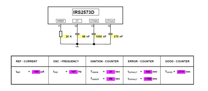
IREF needs to be set to the beginning, because IREF is also used for other settings.
2 V
V 100
I
(1)
IREF
A
REF
20k
R REF
CT sets the full bridge frequency.
I CT,SOURCE / SINK 80 A
147Hz
f
(2)
FB 8 C
8 68nF
CT
CTIGN sets the timing for the ignition pulses.
4
4 1000
C
nF
TIGN
32
32
IGN , ON
(3)
T
6
I
A
TIGN ,SOURCE / SINK
3
(4)
T T IGN , OFF IGN , ON
CTCLK sets the time constants for the EOL (Under Voltage Fault/ Over Voltage Fault)
4 C
4 270nF
TCLK
16,384
16,384
(5)
T UVFAULT
40 A
I , / TCLK SOURCE SINK
4 T
(6)
UVFAULT
T OVFAULT
- 18 -
Page 19
7.2 Dimensioning: EOL settings
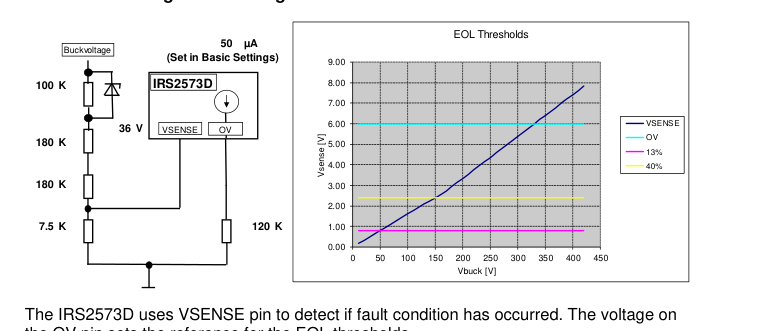
the OV pin sets the reference for the EOL thresholds.
VSENSE <= VOV(1/7.5) → Lamp under voltage fault (13% of OV) VSENSE >= VOV(2/5) → Lamp over voltage fault (40% of OV) VSENSE >= VOV → Buck over voltage threshold (100% of OV)
During the ignition phase the buck voltage is regulated to OV (e.g. 330V). If the buck voltage stays below 13% of OV for more than 442sec or above 40% of OV for 1769sec, the ballast will go to Fault mode and latched (CTCLK=270nF).
7.3 Dimensioning: Buck settings
Lamp parameter Start with the lamp parameter:
PLAMP=73W VLAMP=100V ILAMP=0.73A
Buck current sensing resistor Buck inductor over-current protection is setup by buck current sensing resistor:
9.0A IOC
I 8.1
(7)
I
A
OC,PEAK
OC
- 19 -
Page 20
2.1 V
V
(8)
.0667
BCS
CS
R
8.1A I OC, PEAK
Buck inductor value
Select input voltage for the buck, which is the bus voltage provided by boost PFC stage:
400 VBUS
V
Select nominal frequency of the buck:
f 70kHz
Calculate buck inductor value based on nominal frequency, lamp current, buck input and output voltage:
VOUT T 1
V 733
(9)
L
H
OUT
2 LAMP I
V BUS
1
whereT
andV
V OUT LAMP
f
Buck inductor selection value:
L 750 H
Buck off-time programming capacitor
Determine buck output minimum voltage (lamp minimum voltage after ignition):
20 V (typical )
V OUT ,MIN
Calculate buck minimum frequency in critical conduction mode:
2
V
1
OUT ,MIN
f
V OUT ,MIN
MIN
I L
V
OC,PEAK
BUS 2
1
20 20
14kHz
(10)
8.1 750e 6
400
- 20 -
Page 21
Calculate tOFF:
VOUT ,MIN 1 VBUS tOFF
f
20 1 400
(11)
68
s
14
Calculate CTOFF:
I t
C REF OFF
TOFF VTOFF
100 A68 s
(12)
4.3nF
2 V
Off-time programming capacitor selection value:
3.3nF CTOFF
Current sense and over-current resistor value:
Calculate the nominal value on VSENSE pin (based on nominal lamp voltage):
RVS 4
V
V ,NOM LAMP,NOM
SENSE
RVS1 RVS 2 RVS3 RVS 4
5.7 k
(13)
100
6.1 V
180k 180k
100k 5.7k
Calculate the nominal value on ISENSE pin:
P SENSE
V ISENSE,NOM
VSENSE NOM ,
5.0 .031
(14)
V 6.1
- 21 -
Page 22
Calculate the value of current sense and over current resistors:
VISENSE,NOM
(15)
.043
R CS I LAMP
6.1 OC CS I R
124.
(16)
k
R OC 5.0 I REF
Over-current resistor selection value:
13k ROC
- 22 -
Page 23
8. PCB Layout Considerations
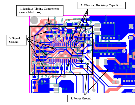
- The programming and timing components should be placed close to the IC with short traces and with ground connections directly to COM-pin (Pin 6). 2. The filter and bootstrap capacitors should also be placed close to the IC with short tracks. 3. All signal ground connections should go directly to the COM pin. 4. There is only one connection from the IC COM to the power ground. The power ground connections should also be as short as possible and with bigger track size.
Disclaimer This reference design is intended for evaluation purposes only and has not been submitted or approved by any external test house for conformance with UL or international safety or performance standards. International Rectifier does not guarantee that this reference design will conform to any such standards.
- 23 -
Page 24
9. Bill of Materials
| Item # | Qty | Manufacturer | Part Number | Description | Reference |
|---|---|---|---|---|---|
| 1 | 1 | IR | IRS2505L | SOT-23 PFC IC | IC1 |
| 2 | 1 | Power Integration | LNK302DN | Link Switch LNK | IC2 |
| 3 | 1 | IR | IRS2573D | HID Ballast Control IC | IC3 |
| 4 | 1 | IR | IRF840 | MOSFET 500V/600V | MBUCK |
| 5 | 1 | IR | IRF830 | MOSFET 500V | MPFC |
| 6 | 5 | IR | IRGR3B60KD2 | IGBT 600V | MIGN, MH1, ML1, MH2, ML2 |
| 7 | 1 | Vishay | 8ETH06 | Diode 600V | DBUCK |
| 8 | 1 | Vishay | LL4148 | Diode, 75V, 100mA | DBUCK1 |
| 9 | 1 | Vishay | BZT52C15 | Zener Diode, 15V, 500mW | DVBB2 |
| 10 | 1 | Vishay | BZT52C36 | Zener Diode, 36V, 500mW | DVS1 |
| 11 | 1 | Diodes Inc. | DF10S | Bridge Rectifier 1A, 1000V | BR1 |
| 12 | 5 | Diodes Inc. | MURS160 | Diode, 600V, 1A, SMB | D3, DVBB1, DLNK1, DLNK2, DCS |
| 13 | 1 | Schindengen | K1V26 | Sidac 240V-270V | DIGN |
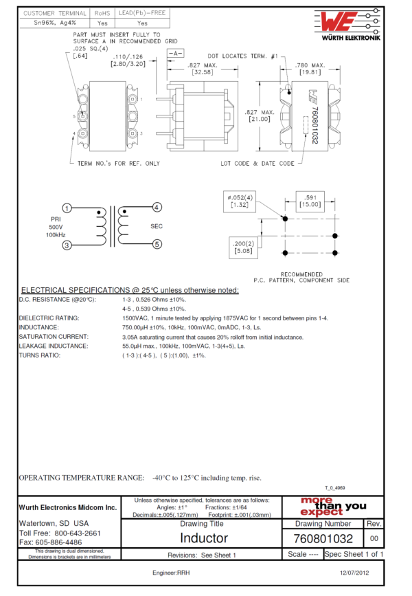
| 14 | 1 | Würth Elektronik | 760801032 | Buck Inductor 0.75mH EE20/10/11 | LBUCK |
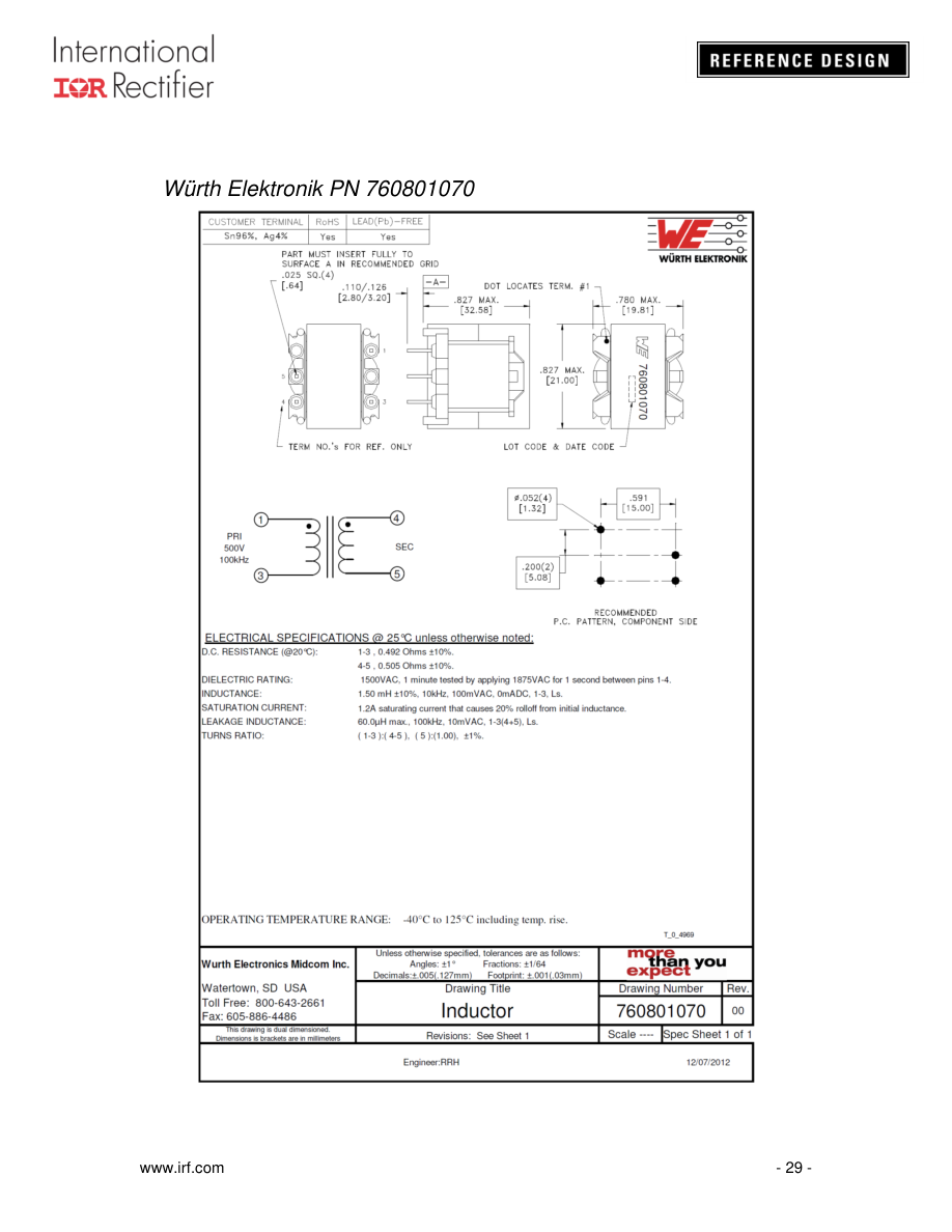
| 15 | 1 | Würth Elektronik | 760801070 | PFC Inductor 1.5mH EE20/10/11 | LPFC |
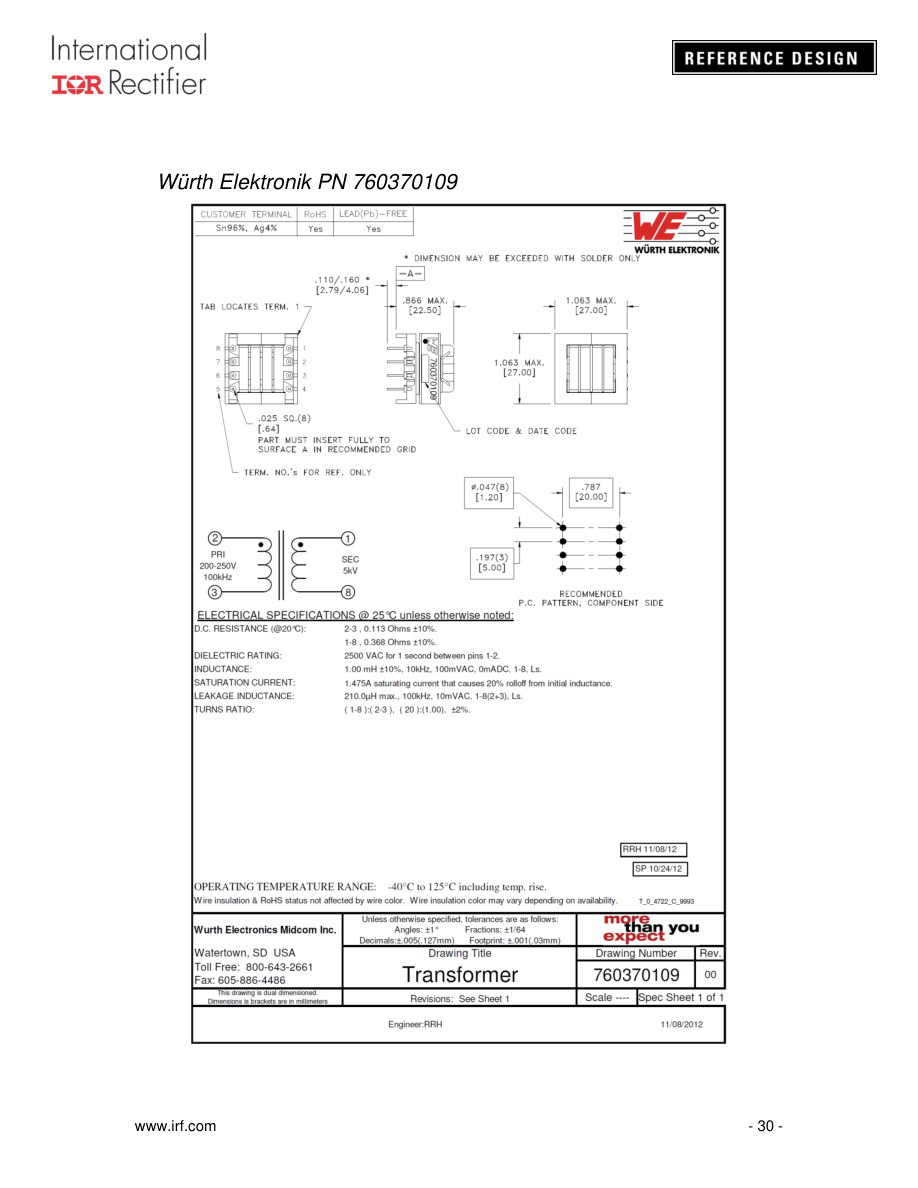
| 16 | 1 | Würth Elektronik | 760370109 | Ignition Transformer 1mH EE25/13/7 | LIGN |
| 17 | 1 | Panasonic | ELF-15N007A | EMI Inductor | L1 |
| 18 | 1 | Epcos | B82144B1225J000 | HF-Inductor | LLINK1 |
| 19 | 1 | Panasonic | ECQ-E4105KF | Capacitor 1µF/400V | CBUCK |
| 20 | 2 | Vishay | 2222 338 20334 | Capacitor 330nF/275VAC X2 | C1,C2 |
| 21 | 1 | Epcos | B32652A6104J | Capacitor 100nF/630V | CIGN |
| 22 | 1 | Roederstein | WY0222MCMBF0K | Capacitor 2.2nF/275VAC Y Cap | CY |
| 23 | 1 | Wima | MKP10 1nF/630V | Capacitor 1nF/630V | COUT |
| 24 | 1 | Panasonic | ECE-A1EN330U | Capacitor 33µF/25V | CLNK3 |
| 25 | 1 | Panasonic | EEU-EB2W220S | Capacitor 22µF/450V | CBUS |
| 26 | 1 | Panasonic | ECA-1HM100I | Capacitor 10µF/50V | CLNK2 |
| 27 | 3 | Panasonic | ECJ-3YF1E225Z | Capacitor, 2.2uF, 25V, 1206 | CVB1, CVB2, CVBB |
| 28 | 1 | Panasonic | ECJ-3YB1E105K | Capacitor, 1uF, 25V, 1206 | CTIGN |
| 1 | Multicomp | MC0805B474K160CT | Capacitor, 470nF, 25V, 0805 | CPFC2 | |
| 30 | 1 | Multicomp | MC0805B274K160CT | Capacitor, 270nF, 16V, 0805 | CTCLK |
| 31 | 1 | Multicomp | MC0805B224K250CT | Capacitor, 220nF, 25V, 0805 | CPFC1 |
| 32 | 6 | Panasonic | ECJ-2YB1H104K | Capacitor, 100nF, 50V, 0805 | CVCC1, COV, COC, CISENSE, CLINK1, CPFC4 |
| 33 | 1 | Panasonic | ECJ-2YB1H683K | Capacitor, 68nF, 50V, 0805 | CCT |
| 34 | 1 | Panasonic | ECJ-2VB1H333K | Capacitor, 33nF, 50V, 0805 | CPCOMP |
| 35 | 2 | Panasonic | ECJ-2VB1H223K | Capacitor, 22nF, 50V, 0805 | CVS, CPFC3 |
| 36 | 1 | Panasonic | ECJ-2VB1H332K | Capacitor, 3.3nF, 50V, 0805 | CTOFF |
| 37 | 1 | Panasonic | ECJ-2VB1H102K | Capacitor, 1nF, 50V, 0805 | CICOMP |
| 38 | 1 | Panasonic | ECJ-2VC1H471J | Capacitor, 470pF, 50V, 0805 | CCS1 |
| 39 | 1 | Multicomp | MCSH21B101K500CT | Capacitor, 100pF, 50V, 0805 | CPFC5 |
| 40 | 1 | Panasonic | ECJ-2VC1H100D | Capacitor, 10pF, 50V, 0805 | CRZX |
- 24 -
Page 25
| 41 | 2 | Panasonic | ERJ-8ENF8203V | Resistor, 820kOhm, 0.25W, 1%, 1206 | RPFC4, RPFC5 |
| 42 | 2 | Panasonic | ERJ-8ENF1803V | Resistor, 180kOhm, 0.25W, 1%, 1206 | RVS1, RVS2 |
| 43 | 1 | Panasonic | ERJ-6ENF1203V | Resistor, 120kOhm, 0.125W,1%,0805 | ROV |
| 44 | 1 | Panasonic | ERJ-8ENF1003V | Resistor, 100kOhm, 0.25W, 1%, 1206 | RVS3 |
| 45 | 5 | Panasonic | ERJ-8ENF6802V | Resistor, 39kOhm, 0.25W, 1%, 1206 | RBB1, RBB2, RBB3, RBB4, RBB5 |
| 46 | 1 | Panasonic | ERJ-6ENF3302V | Resistor, 33kOhm, 0.125W, 1%, 0805 | RZX |
| 47 | 1 | Panasonic | ERJ-6ENF2202V | Resistor, 22kOhm, 0.125W, 1%, 0805 | RPFC1 |
| 48 | 1 | Panasonic | ERJ-6ENF2002V | Resistor, 20kOhm, 0.125W, 1%, 0805 | RIREF |
| 49 | 1 | Panasonic | ERJ-6ENF1602V | Resistor, 16kOhm, 0.125W, 1%, 0805 | RPFC6 |
| 50 | 1 | Panasonic | ERJ-6ENF1502V | Resistor, 15kOhm, 0.125W, 1%, 0805 | RLNK2 |
| 51 | 1 | Panasonic | ERJ-6ENF1302V | Resistor, 13kOhm, 0.125W, 1%, 0805 | ROC |
| 52 | 1 | Panasonic | ERJ-6ENF7501V | Resistor, 7.5kOhm, 0.125W, 1%,0805 | RVS4 |
| 53 | 1 | Panasonic | ERJ-8ENF3301V | Resistor, 3.3kOhm, 0.25W, 1%, 1206 | RLNK3 |
| 54 | 1 | Panasonic | ERJ-6ENF2202V | Resistor, 2.2kOhm, 0.125W, 1%,0805 | RLNK1 |
| 55 | 3 | Panasonic | ERJ-6ENF1001V | Resistor, 1kOhm, 0.125W, 1%, 0805 | RISENSE, RCCS1, RPFC3 |
| 56 | 7 | Panasonic | ERJ-S06F22R0V | Resistor, 22Ohm, 0.125W, 1%, 0805 | RBUCK1, RPFC2, RIGN1, RHO1, RLO1, RHO2, RLO2 |
| 57 | 2 | Panasonic | ERJ-S06F10R0V | Resistor, 10Ohm, 0.125W, 1%, 0805 | RVBB1, RVCC |
| 58 | 8 | Panasonic | ERJ-8RQF3R3V | Resistor, 3.3Ohm, 0.25W, 1%, 1206 | RBCS1, RBCS2, RBCS3, RBCS4, RBCS5, RCS1, RCS2, RCS3 |
| 59 | 3 | Panasonic | ERJ-8RQF2R2V | Resistor, 2.2Ohm, 0.25W, 1%, 1206 | RCS4, RCS5, RCS6 |
| 60 | 2 | Panasonic | ERJ-8RQF1R0V | Resistor, 1Ohm, 0.25W, 1%, 1206 | RPFC7, RPFC8 |
| 61 | 1 | - | - | Resistor 0R Jumper 1206 | ROUT |
| 62 | 1 | Vishay | PR03000201802JAC00 | Resistor 18K/3W | RIGN2 |
| 63 | 2 | Phoenix Contact | MTSB 1.5/3-5.08 | 3-pin Connector | X1, X2 |
| 64 | 2 | Multicomp | MC33282 | Heatsink, TO-220 | DBUCK, MBUCK |
| 65 | 1 | - | - | Radial Fuse, T 2A | F1 |
| 66 | 22 | - | - | Test Points | - |
| 67 | - | - | - | Do not populate | CLNK4, DHO1, DHO2, DLO1, DLO2, LOUT |
TABLE 9.1: IRPLHID2A Bill of Materials.
- 25 -
Page 26
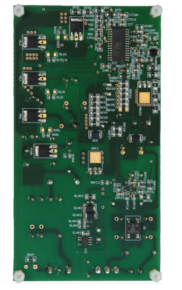
10. IRPLHID2A PCB Layout
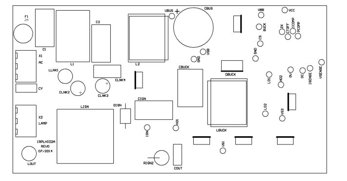
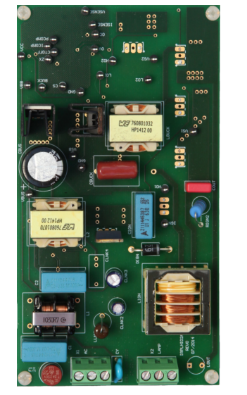
Top Assembly
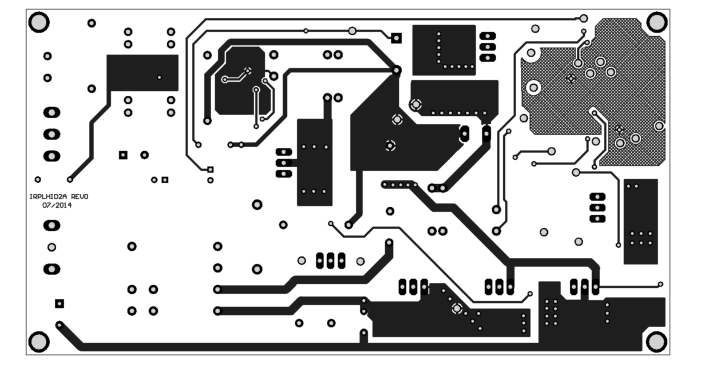
Top Copper
- 26 -
Page 27
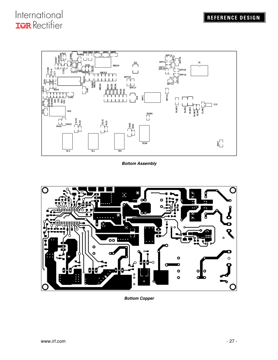
Page 28
- Inductor specification
Würth Elektronik PN 760801032
- 28 -
Page 29
Page 30