
DATASHEET SEARCH SITE
Document overview
- Manufacturer or author: Provided By www.digicamel.com(FREE DATASHEET DOWNLOAD SITE)
- PDF pages: 3
Technical content
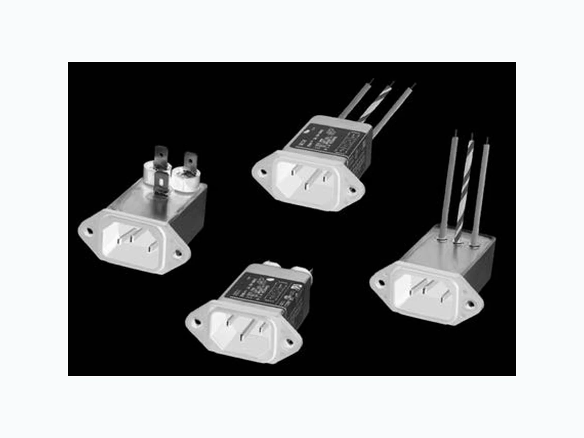
Power Inlet Filters & Power Entry Modules 141 Dimensions are in inches and millimeters unless otherwise specified. Values in italics are metric equivalents. Dimensions are shown for reference purposes only. Specifications subject to change. Corcom Product Guide Catalog: 1654001 Issue Date: 06.2011 For email, phone or live chat, please go to te.com/help corcom.com EC Series E C Series High Performance EMI Power Inlet Filter UL Recognized CSA Certified VDE Approved
- Three element differential mode circuit provides the highest attenuation of any available standard inlet filter
- High common mode inductance
- High differential mode capacitance
- Effective attenuation of Line to Ground and Line to Line noise across the frequency range
- Performance and application similar to the ED series but with higher differential mode performance
- Includes several termination options O rdering Inform ation
3 EC 1
1 – .250 [6.3] spade terminals (back) 2 – .250 [6.3] spade terminals (bottom) 4 – Wire leads (bottom) 8 – Wire leads (back) EC Series Current Rating 1, 3, 6, or 10A Maximum leakage current each Line to Ground: @ 120 VAC 60 Hz: .25 mA @250 VAC 50 Hz: .50 mA Hipot rating (one minute): Line to Ground: 2250 VDC Line to Line: 1450 VDC Rated Voltage (max.): 250 VAC Operating Frequency: 50/60 Hz Rated Current: 1 to 10A Operating Ambient Temperature Range (at rated current Ir): -10°C to +40°C In an ambient temperature (Ta) higher than +40°C the maximum operating current (Io) is calculate d as follows: Io= Ir(85-Ta)/45 Specifications A vailable Part Num bers 1EC1 1EC2 1EC4 1EC8 3EC1 3EC2 3EC4 3EC8 6EC1 6EC2 6EC4 6EC8 10EC1 E lectrical Schem atic LINE LOAD EC1 EC8 EC2 EC4
Dimensions are in inches and millimeters unless otherwise specified. Values in italics are metric equivalents. Dimensions are shown for reference purposes only. Specifications subject to change. Corcom Product Guide Catalog: 1654001 Issue Date: 06.2011 For email, phone or live chat, please go to te.com/help corcom.com EC Series High Performance EMI Power Inlet Filter(continued) GA400: NEMA 5-15P to IEC 60320-1 C-13 line cord A ccessories FA601: Insulating Shroud Dia..413 10.5 Dia..271 6.9 1.39 35.4 .118 3.0 1.17 29.7 .767 19.5 C ase Styles EC1 AD B C E EC2 D E A C B .65 16.5 Max. EC4 C A F F B Brown Green/Yellow BlueD E EC8 C A F F B Brown Green/Yellow Blue DE Recom m ended Panel Cutouts .140 3.56 .062 1.58 .820 20.8 Typ. 1.200 30.48 1.575 40.01 .140 3.56 .234 5.94 .900 22.9 1.200 30.48 1.575 40.01 Front Mount Back Mount Typ. Tolerances ± .005 [0.13] unless otherwise noted Part No. ABCDEF C ase Dim ensions
Power Inlet Filters & Power Entry Modules 143 Dimensions are in inches and millimeters unless otherwise specified. Values in italics are metric equivalents. Dimensions are shown for reference purposes only. Specifications subject to change. Corcom Product Guide Catalog: 1654001 Issue Date: 06.2011 For email, phone or live chat, please go to te.com/help corcom.com EC Series High Performance EMI Power Inlet Filter(continued) Perform ance Data Minimum Insertion Loss Common Mode / Asymmetrical (Line to Ground) Measured in closed 50 Ohm system Differential Mode / Symmetrical (Line to Line) Typical Insertion Loss 1EC 3EC Common Mode / Asymmetrical (L-G) Differential Mode / Symmetrical (L-L) Measured in closed 50 Ohm system 6EC 10EC 0.1 1 10 30 Frequency in MHz db 100 0 0.1 1 10 30 Frequency in MHz db 100 00.1 1 10 30 Frequency in MHz db 100 00.1 1 10 30 Frequency in MHz db 100