

 Download PDF
E3U ECLIPTEK
Document overview
- PDF pages: 3
Technical content
Page 1
Marketing Bulletin
DATE: January 28th, 2008
TO:
All Sales Personnel
FROM: Isaac Gonzalez
RE:
Product Termination
To all concerned parties,
This bulletin is to notify all customers of the discontinuation of the following Ecliptek series effective January 28th, 2008:
Series
Description
Recommended Replacement
RoHS Compliant (Pb-free) Resistance
E3U
E2S
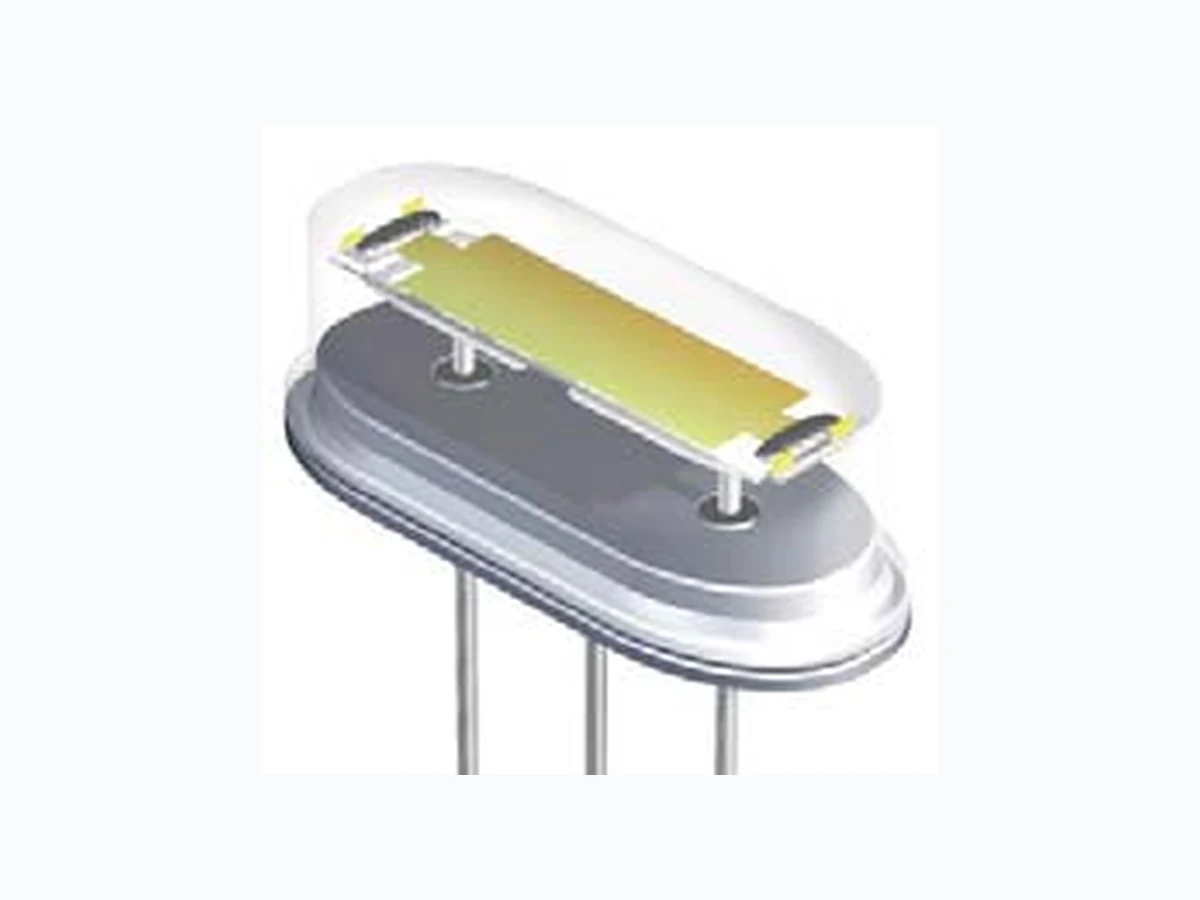
Welded HC-49/UST Crystal
In compliance with our End of Life (EOL) policy, this will serve as advanced notice of product termination. New orders will not be accepted after July 28th, 2008, with delivery to conclude by October 28th, 2008.
If there are any questions pertaining to this bulletin, please feel free to contact me. Thank you again for your cooperation.
Best Regards,
Isaac Gonzalez Configuration Manager Ecliptek Corporation
3545 CADILLAC AVENUE • COSTA MESA, CA 92626-1401 • (714) 433-1200 • Fax (714) 433-1234
Page 2
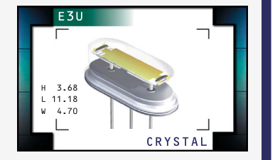
E3U Series
- RoHS Compliant (Pb-Free)
- HC-49/UST package
- AT or BT cut available
- Resistance weld seal
- Tight tolerance/stability
- Insulator tab, and custom lead length
options available
NOTES
__________________________________________________________________________________________________________________________________________________________________________________________________________________________________________________________________________________________________________________________________________________________________________________________
OBSOLETE
__________________________________________________________________________________________________________________________________________________________________________________________________________________________________________________________________________________________________________________________________________________________________________________________
__________________________________________________________________________________________________________________________________________________________________________________________________________________________________________________________________________________________________________________________________________________________________________________________
__________________________________________________________________________________________________________________________________________________________________________________________________________________________________________________________________________________________________________________________________________________________________________________________
__________________________________________________________________________________________________________________________________________________________________________________________________________________________________________________________________________________________________________________________________________________________________________________________
| ELECTRICAL SPECIFICATIONS Frequency Range 3.579545MHz to 50.000MHz Frequency Tolerance / Stability ±50ppm / ±100ppm (Standard), ±30ppm / ±50ppm (AT cut only), ±15ppm / ±30ppm (AT cut only), Over Operating Temperature Range ±15ppm / ±20ppm (AT cut only), or ±10ppm / ±15ppm (AT cut only) Operating Temperature Range 0°C to 70°C (Standard), -20°C to 70°C (AT cut only), or -40°C to 85°C (AT cut only) Aging (at 25°C) ±5ppm / year Maximum Storage Temperature Range -40°C to 85°C Shunt Capacitance 7pF Maximum Insulation Resistance 500 Megaohms Minimum at 100V DC Drive Level 1 mWatt Maximum Load Capacitance (C) 18pF (Standard), Custom C ≥10pF, or Series Resonant L L Drive Level Dependancy (DLD2) 20% of Maximum ESR Limit (from 1µWatt to 1000µWatts) Spurious Response >3dB from Fo to Fo +5000ppm EQUIVALENT SERIES RESISTANCE (ESR), MODE OF OPERATION (MODE), AND CUT Frequency Range ESR (Ω) Mode / Cut Frequency Range ESR (Ω) Mode / Cut 3.579545MHz to 4.999MHz 200 Max Fundamental / AT 15.000MHz to 15.999MHz 60 Max Fundamental / AT 5.000MHz to 5.999MHz 150 Max Fundamental / AT 16.000MHz to 23.999MHz 50 Max Fundamental / AT 6.000MHz to 7.999MHz 120 Max Fundamental / AT 24.000MHz to 29.4912MHz 40 Max Fundamental / AT 8.000MHz to 8.999MHz 90 Max Fundamental / AT 24.000MHz to 40.000MHz 40 Max Fundamental / BT 9.000MHz to 9.999MHz 80 Max Fundamental / AT 28.6363MHz to 29.999MHz 150 Max Third Overtone / AT 10.000MHz to 14.999MHz 70 Max Fundamental / AT 30.000MHz to 50.000MHz 100 Max Third Overtone / AT | |||||
|---|---|---|---|---|---|
| MANUFACTURER ECLIPTEK CORP. | CATEGORY CRYSTAL | SERIES E3U | PACKAGE HC-49/UST | CLASS CR45 | REV.DATE 03/04 |
800-ECLIPTEK www.ecliptek.com for latest revision Specifications subject to change without notice.
Page 3
PART NUMBERING GUIDE
E3U A A 18 - 30.000M - I2
FREQUENCY TOLERANCE / STABILITY
A=±50ppm at 25°C, ±100ppm from 0°C to 70°C B=±50ppm at 25°C, ±100ppm from -20°C to 70°C C=±50ppm at 25°C, ±100ppm from -40°C to 85°C D=±30ppm at 25°C, ±50ppm from 0°C to 70°C E=±30ppm at 25°C, ±50ppm from -20°C to 70°C F=±30ppm at 25°C, ±50ppm from -40°C to 85°C G=±15ppm at 25°C, ±30ppm from 0°C to 70°C H=±15ppm at 25°C, ±30ppm from -20°C to 70°C J=±15ppm at 25°C, ±30ppm from -40°C to 85°C K=±15ppm at 25°C, ±20ppm from 0°C to 70°C L=±15ppm at 25°C, ±20ppm from -20°C to 70°C M=±15ppm at 25°C, ±20ppm from -40°C to 85°C \* N=±10ppm at 25°C, ±15ppm from 0°C to 70°C \* P=±10ppm at 25°C, ±15ppm from -20°C to 70°C \*
\* Frequency Tolerance/Stability options M, N, and P are only available with frequencies greater than 10.000MHz
NOTES
AVAILABLE OPTIONS
Blank=None (Std) CD=Custom Lead Length (3.810 ±0.500mm) CE=Custom Lead Length (4.445 ±0.500mm) I2=Insulator Tab
FREQUENCY
LOAD CAPACITANCE
S=Series XX=XXpF (Custom)
MODE OF OPERATION / CRYSTAL CUT
A=Fundamental / AT B=Third Overtone / AT D=Fundamental / BT
__________________________________________________________________________________________________________________________________________________________________________________________________________________________________________________________________________________________________________________________________________________________________________________________
OBSOLETE
__________________________________________________________________________________________________________________________________________________________________________________________________________________________________________________________________________________________________________________________________________________________________________________________
__________________________________________________________________________________________________________________________________________________________________________________________________________________________________________________________________________________________________________________________________________________________________________________________
__________________________________________________________________________________________________________________________________________________________________________________________________________________________________________________________________________________________________________________________________________________________________________________________
__________________________________________________________________________________________________________________________________________________________________________________________________________________________________________________________________________________________________________________________________________________________________________________________
MECHANICAL DIMENSIONS ALL DIMENSIONS IN MILLIMETERS
Pin 1: Input/Output Pin 2: Case Ground Pin 3: Input/Output
MARKING SPECIFICATIONS
ENVIRONMENTAL/MECHANICAL SPECIFICATIONS
PARAMETER
SPECIFICATION
Fine Leak Test
MIL-STD-883, Method 1014, Condition A
Gross Leak Test
MIL-STD-883, Method 1014, Condition C
Line 1: E XX.XXX M
Lead Integrity
MIL-STD-883, Method 2004
Frequency in MHz
Lead Termination
Sn 2µm - 6µm
(5 Digits Maximum + Decimal)
Mechanical Shock
MIL-STD-202, Method 213, Condition C
Resistance to Soldering Heat MIL-STD-202, Method 210 Resistance to Solvents
MIL-STD-202, Method 215
Solderability
MIL-STD-883, Method 2002
Temperature Cycling
MIL-STD-883, Method 1010
Vibration
MIL-STD-883, Method 2007, Condition A
SERIES PACKAGE CLASS REV.DATE
MANUFACTURER
CATEGORY
HC-49/UST CR45 03/04
ECLIPTEK CORP.
CRYSTAL E3U
800-ECLIPTEK www.ecliptek.com for latest revision Specifications subject to change without notice.