

 Download PDF
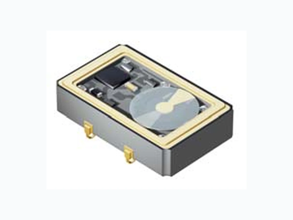
E11C1 ECLIPTEK
Document overview
- PDF pages: 13
Technical content
Page 1
Marketing Bulletin
DATE: May 20, 2003
TO:
Affected Customers
FROM: Mark Stoner
RE:
Product Termination
To all concerned parties,
This bulletin is to notify all customers of the termination of the following Ecliptek series effective May 14th, 2003:
Series
Description
Recommended Replacement
E11C1
Four Pad SMD PECL Oscillator, 5V
E11J1 or E11W1
Four Pad SMD PECL Oscillator, 3.3V E13J1 or E13W1
E13C1 E11C2
Six Pad SMD PECL Oscillator, 5V
E13C2
Six Pad SMD PECL Oscillator, 3.3V
E31C2
Six Pad SMD PECL VCXO, 5V
E32C2
Six Pad SMD PECL VCXO, 3.3V
E11J2 or E11W2 E13J2 or E13W2 E31J2 or E31W2 E32J2 or E32W2
Because of the circumstances surrounding this termination, there will be no end-of-life policy exercised. The series will be terminated with no purchasing or lifetime buy window available. All of us at Ecliptek Corporation apologize for any inconvenience this may have caused and can assure you we are taking measures to insure this will not happen again in the future.
Best Regards,
Mark W. Stoner Director of Marketing Ecliptek Corporation
3545 CADILLAC AVENUE • COSTA MESA, CA 92626-1401 • (714) 433-1200 • Fax (714) 433-1234
Page 2
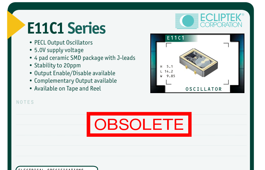
| ELECTRICAL SPECIFICATIONS Frequency Range 19.440MHz to 212.500MHz Operating Temperature Range 0°C to 70°C or -40°C to 85°C Storage Temperature Range -55°C to 125°C Supply Voltage (V ) 5.0V ±5% CC DC Input Current 100mA Maximum Logic Type 100KH Frequency Tolerance / Stability Inclusive of Operating Temp Range, Supply Voltage, ±100ppm, ±50ppm, ±25ppm, or Load, and Aging @25°C over 10 years ±20ppm Maximum Output Voltage Logic High (V ) V -1.025V Minimum OH CC DC Output Voltage Logic Low (V ) V -1.620V Maximum OL CC DC Rise Time / Fall Time 20% to 80% of waveform 2 nSeconds Maximum Duty Cycle at 50% of waveform 50 ±10(%) 50 ±5(%) Load Drive Capability 50 Ohms into V -2.0V CC DC Logic Control / Additional Output No Connect, Enable/Disable, or Complementary Output Enable/Disable Input Voltage V of V -1.475V Maximum Enables Output IL CC DC No Connection Enables Output V of V -1.165V Minimum Disables Output: Logic Low, IH CC DC Disables Complementary Output: Logic High Start Up Time 10 mSeconds Maximum RMS Phase Jitter FJ = 12kHz to 20MHz 1 pSec Maximum | ||||||
|---|---|---|---|---|---|---|
| MANUFACTURER ECLIPTEK CORP. | CATEGORY OSCILLATOR | SERIES E11C1 | PACKAGE CERAMIC | VOLTAGE 5.0V | CLASS OS65 | REV.DATE 10/02 |
800-ECLIPTEK www.ecliptek.com for latest revision 152 Specifications subject to change without notice.
Page 3
E11C1 F 2 C - 155.520M TR
FREQUENCY TOLERANCE & STABILITY/ OPERATING TEMPERATURE RANGE
C=±100ppm Maximum over 0°C to +70°C D=±50ppm Maximum over 0°C to +70°C E=±25ppm Maximum over 0°C to +70°C F=±20ppm Maximum over 0°C to +70°C G=±100ppm Maximum over -40°C to +85°C H=±50ppm Maximum over -40°C to +85°C
DUTY CYCLE
1=50% ±10%, 2=50% ±5%
MECHANICAL DIMENSIONS ALL DIMENSIONS IN MILLIMETERS
AVAILABLE OPTIONS
Blank=Tubes TR=Tape and Reel (Standard)
FREQUENCY
LOGIC CONTROL/ADDITIONAL OUTPUT
A=No Connect B=Enable/Disable C=Complementary Output
SUGGESTED SOLDER PAD LAYOUT ALL DIMENSIONS IN MILLIMETERS
Pin 1: Complementary Output, No Connect, or Enable/Disable
Tolerances = ±0.1
Pin 2: Case Ground Pin 3: Output Pin 4: Supply Voltage
TAPE AND REEL DIMENSIONS ALL DIMENSIONS IN MILLIMETERS
TAPE A B C D E F 24 ±.3 11.5 ±.1 10.75 ±.1 4 ±.2 2±.1 F G H J K L 12 ±.1 B0\* 1.5 +.1-0 A0\* .4 ±.05 K0\*
ENVIRONMENTAL/MECHANICAL SPECIFICATIONS
Characteristic
Specification
Seal Integrity
Bubble test in Perfluorocarbon at +125°C ±5°C for 60 seconds minimum (internal crystal only).
OBSOLETE
Solderability
Sn63 Solder dip at +230°C ±5°C for 5 seconds/95% coverage.
Marking Permanency 10 Strokes with brush after 1 minute soak in solvent, 3 times.
Shock
Random drop on hard wooden plate 3 times from a height of 20cm.
Vibration
Frequency with an amplitude of 1.5mm sweeping between 10Hz to 55Hz within 1 minute (approximately) for 2 hours minimum on each axis (X, Y and Z) for a total of 6 hours.
E11C1
M N O P Q
REEL 1.5 MIN 50 MIN 20.2 MIN 13±.2
40 MIN
R
T U V
S
QTY/REEL
2.5 MIN
30.4 MAX 360 MAX 24.4+2-0
1000
10 MIN
\*Compliant to EIA 481A
MARKING SPECIFICATIONS
Line 1: ECLIPTEK
Line 2: XX.XXX M
Frequency in MHz (5 Digits Maximum + Decimal)
Line 3: XX Y ZZ
Week of Year Last Digit of Year Ecliptek Manufacturing Identifier
5.0V OS65 10/02
800-ECLIPTEK www.ecliptek.com for latest revision 153 Specifications subject to change without notice.
Page 4
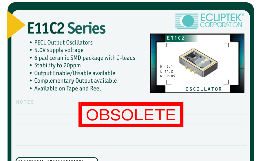
| ELECTRICAL SPECIFICATIONS Frequency Range 19.440MHz to 212.500MHz Operating Temperature Range 0°C to 70°C or -40°C to 85°C Storage Temperature Range -55°C to 125°C Supply Voltage (V ) 5.0V ±5% CC DC Input Current 100mA Maximum Logic Type 100KH Frequency Tolerance / Stability Inclusive of Operating Temp Range, Supply Voltage, ±100ppm, ±50ppm, ±25ppm, or Load, and Aging @25°C over 10 years ±20ppm Maximum Output Voltage Logic High (V ) V -1.025V Minimum OH CC DC Output Voltage Logic Low (V ) V -1.620V Maximum OL CC DC Rise Time / Fall Time 20% to 80% of waveform 2 nSeconds Maximum Duty Cycle at 50% of waveform 50 ±10(%) 50 ±5(%) Load Drive Capability 50 Ohms into V -2.0V CC DC Logic Control / Additional Output No Connect, Enable/Disable, Complementary Output, or Complementary Output and Enable/Disable Enable/Disable Input Voltage V of V -1.475V Maximum Enables Output IL CC DC No Connection Enables Output V of V -1.165V Minimum Disables Output: Logic Low IH CC DC Disables Complementary Output: Logic High Start Up Time 10 mSeconds Maximum RMS Phase Jitter FJ = 12kHz to 20MHz 1 pSec Maximum | ||||||
|---|---|---|---|---|---|---|
| MANUFACTURER ECLIPTEK CORP. | CATEGORY OSCILLATOR | SERIES E11C2 | PACKAGE CERAMIC | VOLTAGE 5.0V | CLASS OS66 | REV.DATE 10/02 |
800-ECLIPTEK www.ecliptek.com for latest revision 154 Specifications subject to change without notice.
Page 5
E11C2 F 2 C - 155.520M TR
FREQUENCY TOLERANCE & STABILITY/ OPERATING TEMPERATURE RANGE
C=±100ppm Maximum over 0°C to +70°C D=±50ppm Maximum over 0°C to +70°C E=±25ppm Maximum over 0°C to +70°C F=±20ppm Maximum over 0°C to +70°C G=±100ppm Maximum over -40°C to +85°C H=±50ppm Maximum over -40°C to +85°C
A=No Connect
DUTY CYCLE
1=50% ±10%, 2=50% ±5%
MECHANICAL DIMENSIONS ALL DIMENSIONS IN MILLIMETERS
TAPE AND REEL DIMENSIONS ALL DIMENSIONS IN MILLIMETERS
TAPE A B C D E F 24 ±.3 11.5 ±.1 10.75 ±.1 4 ±.2 2±.1 F G H J K L 12 ±.1 B0\* 1.5 +.1-0 A0\* .4 ±.05 K0\*
ENVIRONMENTAL/MECHANICAL SPECIFICATIONS
Characteristic
Specification
OBSOLETE
Seal Integrity
Bubble test in Perfluorocarbon at +125°C ±5°C for 60 seconds minimum (internal crystal only).
Solderability
Sn63 Solder dip at +230°C ±5°C for 5 seconds/95% coverage.
Marking Permanency 10 Strokes with brush after 1 minute soak in solvent, 3 times.
Shock
Random drop on hard wooden plate 3 times from a height of 20cm.
Vibration
Frequency with an amplitude of 1.5mm sweeping between 10Hz to 55Hz within 1 minute (approximately) for 2 hours minimum on each axis (X, Y and Z) for a total of 6 hours.
E11C2
AVAILABLE OPTIONS
Blank=Tubes TR=Tape and Reel (Standard)
FREQUENCY
LOGIC CONTROL/ADDITIONAL OUTPUT
D=Complementary Output and Enable/Disable
B=Enable/Disable
E=Complementary Output (Alt. Pin Configuration)
C=Complementary Output
G=Complementary Output and Enable/Disable (Alt. Pin Configuration)
PIN CONNECTIONS TABLE
M N O P Q
REEL 1.5 MIN 50 MIN 20.2 MIN 13±.2
40 MIN
R
T U V
S
QTY/REEL
2.5 MIN
30.4 MAX 360 MAX 24.4+2-0
1000
10 MIN
\*Compliant to EIA 481A
MARKING SPECIFICATIONS
Line 1: ECLIPTEK
Line 2: XX.XXX M
Frequency in MHz (5 Digits Maximum + Decimal)
Line 3: XX Y ZZ
Week of Year Last Digit of Year Ecliptek Manufacturing Identifier
5.0V OS66 10/02
800-ECLIPTEK www.ecliptek.com for latest revision 155 Specifications subject to change without notice.
Page 6
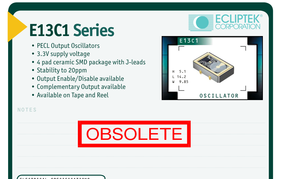
| ELECTRICAL SPECIFICATIONS Frequency Range 19.440MHz to 212.500MHz Operating Temperature Range 0°C to 70°C or -40°C to 85°C Storage Temperature Range -55°C to 125°C Supply Voltage (V ) 3.3V ±5% CC DC Input Current 75mA Maximum Logic Type 100KH Frequency Tolerance / Stability Inclusive of Operating Temp Range, Supply Voltage, ±100ppm, ±50ppm, ±25ppm, or Load, and Aging @25°C over 10 years ±20ppm Maximum Output Voltage Logic High (V ) V -1.025V Minimum OH CC DC Output Voltage Logic Low (V ) V -1.620V Maximum OL CC DC Rise Time / Fall Time 20% to 80% of waveform 2 nSeconds Maximum Duty Cycle at 50% of waveform 50 ±10(%) 50 ±5(%) Load Drive Capability 50 Ohms into V -2.0V CC DC Logic Control / Additional Output No Connect, Enable/Disable, or Complementary Output Enable/Disable Input Voltage V of V -1.475V Maximum Enables Output IL CC DC No Connection Enables Output V of V -1.165V Minimum Disable Output: Logic Low IH CC DC Disables Complementary Output: Logic High Start Up Time 10 mSeconds Maximum RMS Phase Jitter FJ = 12kHz to 20MHz 1 pSec Maximum | ||||||
|---|---|---|---|---|---|---|
| MANUFACTURER ECLIPTEK CORP. | CATEGORY OSCILLATOR | SERIES E13C1 | PACKAGE CERAMIC | VOLTAGE 3.3V | CLASS OS63 | REV.DATE 10/02 |
800-ECLIPTEK www.ecliptek.com for latest revision 156 Specifications subject to change without notice.
Page 7
E13C1 F 2 C - 155.520M TR
FREQUENCY TOLERANCE & STABILITY/ OPERATING TEMPERATURE RANGE
C=±100ppm Maximum over 0°C to +70°C D=±50ppm Maximum over 0°C to +70°C E=±25ppm Maximum over 0°C to +70°C F=±20ppm Maximum over 0°C to +70°C G=±100ppm Maximum over -40°C to +85°C H=±50ppm Maximum over -40°C to +85°C
DUTY CYCLE
1=50% ±10%, 2=50% ±5%
MECHANICAL DIMENSIONS ALL DIMENSIONS IN MILLIMETERS
AVAILABLE OPTIONS
Blank=Tubes TR=Tape and Reel (Standard)
FREQUENCY
LOGIC CONTROL/ADDITIONAL OUTPUT
A=No Connect B=Enable/Disable C=Complementary Output
SUGGESTED SOLDER PAD LAYOUT ALL DIMENSIONS IN MILLIMETERS
Pin 1: Complementary Output, No Connect, or Enable/Disable
Tolerances = ±0.1
Pin 2: Case Ground Pin 3: Output Pin 4: Supply Voltage
TAPE AND REEL DIMENSIONS ALL DIMENSIONS IN MILLIMETERS
TAPE A B C D E F 24 ±.3 11.5 ±.1 10.75 ±.1 4 ±.2 2±.1 F G H J K L 12 ±.1 B0\* 1.5 +.1-0 A0\* .4 ±.05 K0\*
ENVIRONMENTAL/MECHANICAL SPECIFICATIONS
Characteristic
Specification
OBSOLETE
Seal Integrity
Bubble test in Perfluorocarbon at +125°C ±5°C for 60 seconds minimum (internal crystal only).
Solderability
Sn63 Solder dip at +230°C ±5°C for 5 seconds/95% coverage.
Marking Permanency 10 Strokes with brush after 1 minute soak in solvent, 3 times.
Shock
Random drop on hard wooden plate 3 times from a height of 20cm.
Vibration
Frequency with an amplitude of 1.5mm sweeping between 10Hz to 55Hz within 1 minute (approximately) for 2 hours minimum on each axis (X, Y and Z) for a total of 6 hours.
E13C1
M N O P Q
REEL 1.5 MIN 50 MIN 20.2 MIN 13±.2
40 MIN
R
T U V
S
QTY/REEL
2.5 MIN
30.4 MAX 360 MAX 24.4+2-0
1000
10 MIN
\*Compliant to EIA 481A
MARKING SPECIFICATIONS
Line 1: ECLIPTEK
Line 2: XX.XXX M
Frequency in MHz (5 Digits Maximum + Decimal)
Line 3: XX Y ZZ
Week of Year Last Digit of Year Ecliptek Manufacturing Identifier
3.3V OS63 10/02
800-ECLIPTEK www.ecliptek.com for latest revision 157 Specifications subject to change without notice.
Page 8
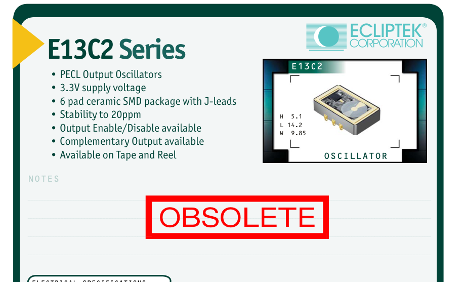
| ELECTRICAL SPECIFICATIONS Frequency Range 19.440MHz to 212.500MHz Operating Temperature Range 0°C to 70°C or -40°C to 85°C Storage Temperature Range -55°C to 125°C Supply Voltage (V ) 3.3V ±5% CC DC Input Current 75mA Maximum Logic Type 100KH Frequency Tolerance / Stability Inclusive of Operating Temp Range, Supply Voltage, ±100ppm, ±50ppm, ±25ppm, or Load, and Aging @25°C over 10 years ±20ppm Maximum Output Voltage Logic High (V ) V -1.025V Minimum OH CC DC Output Voltage Logic Low (V ) V -1.620V Maximum OL CC DC Rise Time / Fall Time 20% to 80% of waveform 2 nSeconds Maximum Duty Cycle at 50% of waveform 50 ±10(%) 50 ±5(%) Load Drive Capability 50 Ohms into V -2.0V CC DC Logic Control / Additional Output No Connect, Enable/Disable, Complementary Output, or Complementary Output and Enable/Disable Enable/Disable Input Voltage V of V -1.475V Maximum Enables Output IL CC DC No Connection Enables Output V of V -1.165V Minimum Disables Output: Logic Low IH CC DC Disables Complementary Output: Logic High Start Up Time 10 mSeconds Maximum RMS Phase Jitter FJ = 12kHz to 20MHz 1 pSec Maximum | ||||||
|---|---|---|---|---|---|---|
| MANUFACTURER ECLIPTEK CORP. | CATEGORY OSCILLATOR | SERIES E13C2 | PACKAGE CERAMIC | VOLTAGE 3.3V | CLASS OS64 | REV.DATE 10/02 |
800-ECLIPTEK www.ecliptek.com for latest revision 158 Specifications subject to change without notice.
Page 9
E13C2 F 2 C - 155.520M TR
FREQUENCY TOLERANCE & STABILITY/ OPERATING TEMPERATURE RANGE
C=±100ppm Maximum over 0°C to +70°C D=±50ppm Maximum over 0°C to +70°C E=±25ppm Maximum over 0°C to +70°C F=±20ppm Maximum over 0°C to +70°C G=±100ppm Maximum over -40°C to +85°C H=±50ppm Maximum over -40°C to +85°C
A=No Connect
DUTY CYCLE
1=50% ±10%, 2=50% ±5%
MECHANICAL DIMENSIONS ALL DIMENSIONS IN MILLIMETERS
SUGGESTED SOLDER PAD LAYOUT
TAPE AND REEL DIMENSIONS ALL DIMENSIONS IN MILLIMETERS
TAPE A B C D E F 24 ±.3 11.5 ±.1 10.75 ±.1 4 ±.2 2±.1 F G H J K L 12 ±.1 B0\* 1.5 +.1-0 A0\* .4 ±.05 K0\*
ENVIRONMENTAL/MECHANICAL SPECIFICATIONS
Characteristic
Specification
OBSOLETE
Seal Integrity
Bubble test in Perfluorocarbon at +125°C ±5°C for 60 seconds minimum (internal crystal only).
Solderability
Sn63 Solder dip at +230°C ±5°C for 5 seconds/95% coverage.
Marking Permanency
10 Strokes with brush after 1 minute soak in solvent, 3 times.
Shock
Random drop on hard wooden plate 3 times from a height of 20cm.
Vibration
Frequency with an amplitude of 1.5mm sweeping between 10Hz to 55Hz within 1 minute (approximately) for 2 hours minimum on each axis (X, Y and Z) for a total of 6 hours.
E13C2
AVAILABLE OPTIONS
Blank=Tubes TR=Tape and Reel (Standard)
FREQUENCY
LOGIC CONTROL/ADDITIONAL OUTPUT
D=Complementary Output and Enable/Disable
B=Enable/Disable
E=Complementary Output (Alt. Pin Configuration)
C=Complementary Output
G=Complementary Output and Enable/Disable (Alt. Pin Configuration)
PIN CONNECTIONS TABLE
M N O P Q
REEL 1.5 MIN 50 MIN 20.2 MIN 13±.2
40 MIN
R
T U V
S
QTY/REEL
2.5 MIN
30.4 MAX 360 MAX 24.4+2-0
1000
10 MIN
\*Compliant to EIA 481A
MARKING SPECIFICATIONS
Line 1: ECLIPTEK
Line 2: XX.XXX M
Frequency in MHz (5 Digits Maximum + Decimal)
Line 3: XX Y ZZ
Week of Year Last Digit of Year Ecliptek Manufacturing Identifier
3.3V OS64 10/02
800-ECLIPTEK www.ecliptek.com for latest revision 159 Specifications subject to change without notice.
Page 10
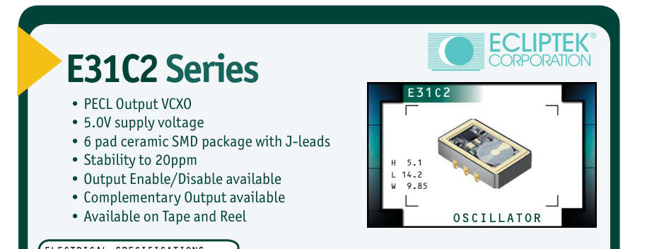
| ELECTRICAL SPECIFICATIONS Frequency Range 19.440MHz to 83.333MHz Operating Temperature Range 0°C to 70°C or -40°C to 85°C Storage Temperature Range -55°C to 125°C OBSOLETE Supply Voltage (V ) 5.0V ±5% CC DC Input Current 100mA Maximum Logic Type 100KH Frequency Tolerance / Stability Inclusive of Operating Temp Range, Supply Voltage, ±50ppm, ±25ppm, or Load, and Aging @25°C over 10 years ±20ppm Maximum Output Voltage Logic High (V ) V -1.025V Minimum OH CC DC Output Voltage Logic Low (V ) V -1.620V Maximum OL CC DC Rise Time / Fall Time 20% to 80% of waveform 2 nSeconds Maximum Duty Cycle at 50% of waveform 50 ±10(%) 50 ±5(%) Load Drive Capability 50 Ohms into V -2.0V CC DC Additional Output / Logic Control No Connect and Single Output Enable/Disable and Single Output No Connect and Complementary Output or Enable/Disable and Complementary Output Enable/Disable Input Voltage V of V -1.475V Maximum Enables Output IL CC DC No Connection Enables Output V of V -1.165V Minimum Disables Output: Logic Low IH CC DC Disables Complementary Output: Logic High Start Up Time 10 mSeconds Maximum RMS Phase Jitter FJ = 12kHz to 20MHz 1 pSec Maximum Absolute Pull Range (APR) Inclusive of Operating Temp Range, Supply Voltage, ±50ppm Minimum Load, and Aging @25°C over 10 years Linearity 20%, 15%, or 10% Maximum Control Voltage (V): Test Conditions for APR 2.5V ±2.0V C DC DC Control Voltage Range (V ) 0.0V to V CR DC CC Center Control Voltage 2.5V DC Transfer Function Positive Transfer Characteristic Input Impedance 50kOhms Typical Modulation Bandwidth at -3dB with Control Voltage of +2.5V 10kHz Minimum DC | ||||||
|---|---|---|---|---|---|---|
| MANUFACTURER ECLIPTEK CORP. | CATEGORY OSCILLATOR | SERIES E31C2 | PACKAGE CERAMIC | VOLTAGE 5.0V | CLASS OS68 | REV.DATE 10/02 |
800-ECLIPTEK www.ecliptek.com for latest revision 188 Specifications subject to change without notice.
Page 11
E31C2 F 3 A 2 C - 77.760M TR
FREQUENCY TOLERANCE & STABILITY/
OPERATING TEMPERATURE RANGE
D=±50ppm Maximum over 0°C to +70°C E=±25ppm Maximum over 0°C to +70°C F=±20ppm Maximum over 0°C to +70°C H=±50ppm Maximum over -40°C to +85°C
APR 3=±50ppm Minimum
LINEARITY
A=20% B=15% C=10%
MECHANICAL DIMENSIONS ALL DIMENSIONS IN MILLIMETERS
Pin 1: Voltage Control Pin 2: Enable/Disable or No Connect Pin 3: Case Ground
Pin 4: Output Pin 5: Complementary Output or No Connect
TAPE AND REEL DIMENSIONS
Pin 6: Supply Voltage
ALL DIMENSIONS IN MILLIMETERS
TAPE A B C D E F 24 ±.3 11.5 ±.1 10.75 ±.1 4 ±.2 2±.1 F G H J K L 12 ±.1 B0\* 1.5 +.1-0 A0\* .4 ±.05 K0\*
ENVIRONMENTAL/MECHANICAL SPECIFICATIONS
Characteristic
Specification
Seal Integrity
Bubble test in Perfluorocarbon at +125°C ±5°C for 60 seconds
OBSOLETE
minimum (internal crystal only).
Solderability
Sn63 Solder dip at +230°C ±5°C for 5 seconds/95% coverage.
Marking Permanency 10 Strokes with brush after 1 minute soak in solvent, 3 times.
Shock
Random drop on hard wooden plate 3 times from a height of 20cm.
Vibration
Frequency with an amplitude of 1.5mm sweeping between 10Hz to 55Hz within 1 minute (approximately) for 2 hours minimum on each axis (X, Y and Z) for a total of 6 hours.
E31C2
AVAILABLE OPTIONS
Blank=Tubes TR = Tape and Reel (Standard)
FREQUENCY
ADDITIONAL OUTPUT/LOGIC CONTROL
A=No Connect and Single Output B=Enable/Disable and Single Output C=No Connect and Complementary Output D=Enable/Disable and Complementary Output
DUTY CYCLE
1=50 ±10(%), 2=50 ±5(%)
SUGGESTED SOLDER PAD LAYOUT ALL DIMENSIONS IN MILLIMETERS
Tolerances = ±0.1
M N O P Q
REEL 1.5 MIN 50 MIN 20.2 MIN 13±.2
40 MIN
R
T U V
S
QTY/REEL
2.5 MIN
30.4 MAX 360 MAX 24.4+2-0
1000
10 MIN
\*Compliant to EIA 481A
MARKING SPECIFICATIONS
Line 1: ECLIPTEK
Line 2: XX.XXX M
Frequency in MHz (5 Digits Maximum + Decimal)
Line 3: XX Y ZZ
Week of Year Last Digit of Year Ecliptek Manufacturing Identifier
5.0V OS68 10/02
800-ECLIPTEK www.ecliptek.com for latest revision 189 Specifications subject to change without notice.
Page 12
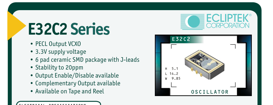
| ELECTRICAL SPECIFICATIONS Frequency Range 19.440MHz to 83.333MHz Operating Temperature Range 0°C to 70°C or -40°C to 85°C OBSOLETE Storage Temperature Range -55°C to 125°C Supply Voltage (V ) 3.3V ±5% CC DC Input Current 75mA Maximum Logic Type 100KH Frequency Tolerance / Stability Inclusive of Operating Temp Range, Supply Voltage, ±50ppm, ±25ppm, or Load, and Aging @25°C over 10 years ±20ppm Maximum Output Voltage Logic High (V ) V -1.025V Minimum OH CC DC Output Voltage Logic Low (V ) V -1.620V Maximum OL CC DC Rise Time / Fall Time 20% to 80% of waveform 2 nSeconds Maximum Duty Cycle at 50% of waveform 50 ±10(%) 50 ±5(%) Load Drive Capability 50 Ohms into V -2.0V CC DC Additional Output / Logic Control No Connect and Single Output Enable/Disable and Single Output No Connect and Complementary Output or Enable/Disable and Complementary Output Enable/Disable Input Voltage V of V -1.475V Maximum Enables Output IL CC DC No Connection Enables Output V of V -1.165V Minimum Disables Output: Logic Low IH CC DC Disables Complementary Output: Logic High Start Up Time 10 mSeconds Maximum RMS Phase Jitter FJ = 12kHz to 20MHz 1 pSec Maximum Absolute Pull Range (APR) Inclusive of Operating Temp Range, Supply Voltage, ±50ppm Minimum Load, and Aging @25°C over 10 years Linearity 20%, 15%, or 10% Maximum Control Voltage (V): Test Conditions for APR 1.65V ±1.35V C DC DC Control Voltage Range (V ) 0.0V to V CR DC CC Center Control Voltage 1.65V DC Transfer Function Positive Transfer Characteristic Input Impedance 50kOhms Typical Modulation Bandwidth at -3dB with Control Voltage of +1.65V 10kHz Minimum DC | ||||||
|---|---|---|---|---|---|---|
| MANUFACTURER ECLIPTEK CORP. | CATEGORY OSCILLATOR | SERIES E32C2 | PACKAGE CERAMIC | VOLTAGE 3.3V | CLASS OS67 | REV.DATE 10/02 |
800-ECLIPTEK www.ecliptek.com for latest revision 190 Specifications subject to change without notice.
Page 13
E32C2 F 3 A 2 C - 77.760M TR
FREQUENCY TOLERANCE & STABILITY/
OPERATING TEMPERATURE RANGE
D=±50ppm Maximum over 0°C to +70°C E=±25ppm Maximum over 0°C to +70°C F=±20ppm Maximum over 0°C to +70°C H=±50ppm Maximum over -40°C to +85°C
APR 3=±50ppm Minimum
LINEARITY
A=20% B=15% C=10%
MECHANICAL DIMENSIONS ALL DIMENSIONS IN MILLIMETERS
Pin 1: Voltage Control Pin 2: Enable/Disable or No Connect Pin 3: Case Ground
Pin 4: Output Pin 5: Complementary Output or No Connect
TAPE AND REEL DIMENSIONS
Pin 6: Supply Voltage
ALL DIMENSIONS IN MILLIMETERS
TAPE A B C D E F 24 ±.3 11.5 ±.1 10.75 ±.1 4 ±.2 2±.1 F G H J K L 12 ±.1 B0\* 1.5 +.1-0 A0\* .4 ±.05 K0\*
ENVIRONMENTAL/MECHANICAL SPECIFICATIONS
Characteristic
Specification
OBSOLETE
Seal Integrity
Bubble test in Perfluorocarbon at +125°C ±5°C for 60 seconds minimum (internal crystal only).
Solderability
Sn63 Solder dip at +230°C ±5°C for 5 seconds/95% coverage.
Marking Permanency 10 Strokes with brush after 1 minute soak in solvent, 3 times.
Shock
Random drop on hard wooden plate 3 times from a height of 20cm.
Vibration
Frequency with an amplitude of 1.5mm sweeping between 10Hz to 55Hz within 1 minute (approximately) for 2 hours minimum on each axis (X, Y and Z) for a total of 6 hours.
E32C2
AVAILABLE OPTIONS
Blank=Tubes TR = Tape and Reel (Standard)
FREQUENCY
ADDITIONAL OUTPUT/LOGIC CONTROL
A=No Connect and Single Output B=Enable/Disable and Single Output C=No Connect and Complementary Output D=Enable/Disable and Complementary Output
DUTY CYCLE
1=50 ±10(%), 2=50 ±5(%)
SUGGESTED SOLDER PAD LAYOUT ALL DIMENSIONS IN MILLIMETERS
Tolerances = ±0.1
M N O P Q
REEL 1.5 MIN 50 MIN 20.2 MIN 13±.2
40 MIN
R
T U V
S
QTY/REEL
2.5 MIN
30.4 MAX 360 MAX 24.4+2-0
1000
10 MIN
\*Compliant to EIA 481A
MARKING SPECIFICATIONS
Line 1: ECLIPTEK
Line 2: XX.XXX M
Frequency in MHz (5 Digits Maximum + Decimal)
Line 3: XX Y ZZ
Week of Year Last Digit of Year Ecliptek Manufacturing Identifier
3.3V OS67 10/02