

 Download PDF
E19 ZFSWITCHES
Document overview
- PDF pages: 3
Technical content
Page 1
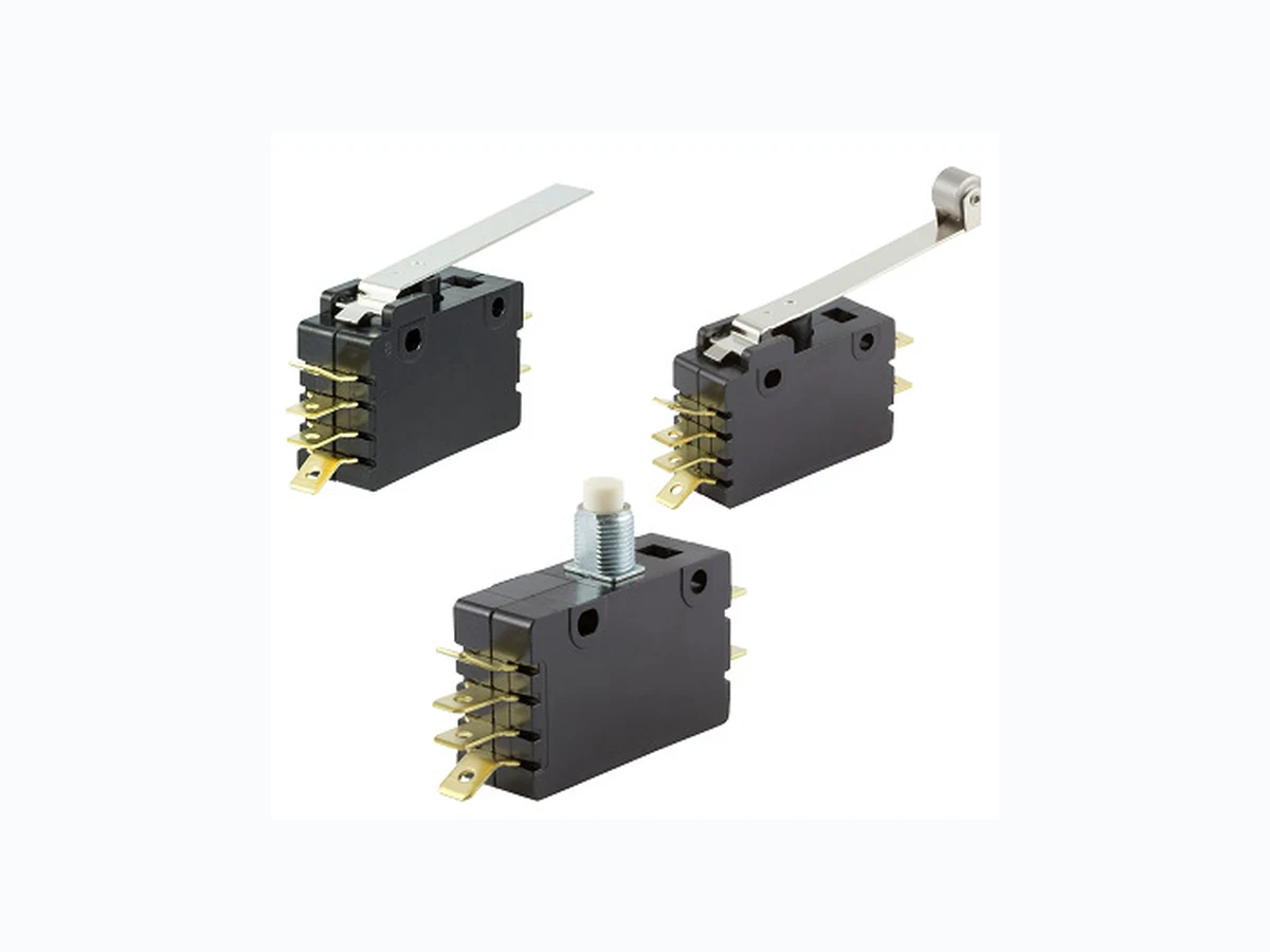
Snap Action Switch
Double Pole General Purpose
E19, E20, G20
Features
- Choice of 3 current ratings
- Long life coil spring, snap action mechanism
- Agency approved extended life versions available
- RoHS compliant
- High temperature versions available – contact factory
Typical Applications
- Household appliances
- Automated assembly lines
- Brake switch on utility vehicles
- Industrial and accessible door openers
- Vending machines
Example: E19-00A0 is a 15 A, normally open DPDT pole switch with a standard ratio button
Part Number Breakdown
E19-00A0
actuator.
Type1
Actuator1
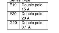
Series Type
Circuitry
| 0 | Double Throw |
| 1 | Normally Open |
| 2 | Normally Closed |
| 0 | Standard ratio actuator or button |
| 5 | High ratio actuator |
| A | Button |
| H | Lever |
| J | Button with ferrule |
| K | Roller |
| M | Button with extra over-travel and ferrule |
1See Actuator Specifications section for available actuator/type combinations
Electrical Specifications per UL1054 – Min 6000 Operations
| E19 | 6000 operations; 100,000 available – contact factory | 15 A, 125 / 250 VAC ¾ HP, 125 VAC / 1 ½ HP, 250 VAC |
| E20 | 6000 operations | 20 A, 125 / 250 VAC 1 HP, 125 VAC / 2 HP, 250 VAC |
| G20 | 100,000 operations | 0.1 A, 125 VAC |
Commonly Stocked Distributor Parts E19-00A0
E19-00M0
E20-00H0
E20-50K0
E19-00H0
E19-50H0
E20-00K0
E19-00J0
E19-50K0
E20-00M0
E19-00K0
E20-00A0
E20-50H0
Note: Part numbers with a leading 0 are functionally no different than without a leading 0 (ex.: 0E19-00A0 is the same switch as E19- 00A0)
Page 1 of 3, Last update 2016-01-20, Specifications subject to change without notice.
Page 2
Actuator Specifications4
E19/G20 Series
Operating Point5
Actuator
Max
Max
Operating Pre-Travel Force g (lb) mm (in)
mm (in)
A
850 (1.87) 1.27 (0.050) 7.24 ± 0.76 (0.285 ± 0.030)
H
205 (0.45) 6.99 (0.275) 7.92 ± 1.57 (0.312 ± 0.062)
H High ratio
130 (0.28) 10.16 (0.400) 7.14 ± 1.57 (0.281 ± 0.062)
J
850 (1.87) 1.27 (0.050) 17.02 ± 0.76 (0.670 ± 0.030)
K
212 (0.47) 6.35 (0.250) 18.24 ± 1.57 (0.718 ± 0.062)
High ratio K
150 (0.33) 7.92 (0.312) 17.45 ± 1.57 (0.687 ± 0.062)
M
850 (1.87) 1.27 (0.050) 20.62 ± 0.76 (0.812 ± 0.030)
E20 Series
Operating Point5
Actuator
Max
Max
Operating
Pre-Travel Force g (lb)
mm (in)
mm (in)
A
1280 (2.82) 2.54 (0.100) 6.30 ± 0.76 (0.248 ± 0.030)
H
425 (0.94) 8.38 (0.330) 11.89 ± 1.57 (0.468 ± 0.062)
H High ratio
285 (0.63) 15.24 (0.600) 11.10 ± 1.57 (0.437 ± 0.062)
J
1280 (2.82) 2.54 (0.100) 6.30 ± 0.76 (0.248 ± 0.030)
K
425 (0.94) 8.84 (0.348) 21.84 ± 1.57 (0.860 ± 0.062)
High ratio K
312 (0.69) 13.34 (0.525) 21.03 ± 1.57 (0.828 ± 0.062)
M
1280 (2.82) 2.54 (0.100) 19.66 ± 0.76 (0.774 ± 0.030)
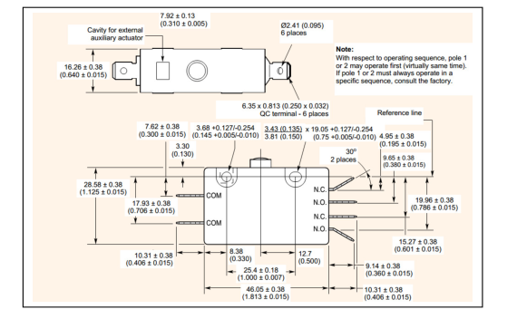
4Contact factory regarding combinations not shown 5Measured above reference line; refer to dimensional drawing below
Min Over-
Max Actuation Length6
Travel
Movement Differential
mm (in)
mm (in)
mm (in) N/A
2.03 (0.080) 0.38 (0.015) 4.75 (0.187) 2.36 (0.093) 38.10 (1.500) 4.75 (0.187) 3.56 (0.140) 44.45 (1.750) 2.30 (0.080) 0.38 (0.015)
N/A
4.75 (0.187) 2.36 (0.093) 35.33 (1.391) 4.75 (0.187) 3.56 (0.140) 41.78 (1.645) 5.54 (0.218) 0.38 (0.015)
N/A
Min Over-
Max Actuation Length6
Travel
Movement Differential
mm (in)
mm (in)
mm (in) N/A
1.27 (0.050) 0.38 (0.015) 3.96 (0.156) 1.27 (0.050) 20.85 (0.821) 3.96 (0.156) 2.03 (0.080) 27.20 (1.071) 1.27 (0.050) 0.38 (0.015)
N/A
3.96 (0.156) 1.14 (0.045) 17.48 (0.688) 3.71 (0.146) 1.91 (0.075) 22.91 (0.902) 4.78 (0.188) 0.38 (0.015)
N/A
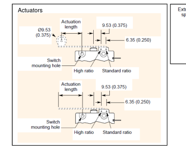
6Actuator tolerances ± 0.791 mm (0.031”); E14 H and K actuators are shorter and formed up 11⁰ at the button
Material Specifications
Case Actuating Button Common Terminal
NO and NC Terminal
Moving Blade
Spring Auxiliary Actuators Roller
Contacts
Environmental Specifications
Temperature Rating
Flammability Rating
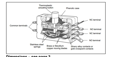
Dimensions – see page 3
Page 2 of 3, Last update 2016-01-20, Specifications subject to change without notice.
General Purpose Phenolic Thermoplastic Copper Alloy Copper Alloy (E13, G13) Copper (E14) Copper Alloy (E13, G13) Copper (E14) Stainless Steel
Cold-Rolled Steel (Nickel-Plated) Sintered Stainless Steel Gold Crosspoint (G13) Silver Alloy (E13, E14)
105 ⁰C (221 ⁰F) standard 150 ⁰C (302 ⁰F) available
UL94HB
Page 3
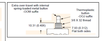
Dimensions – mm (inches)
Page 3 of 3, Last update 2016-01-20, Specifications subject to change without notice.