
E11 ETC2
Document overview
- Manufacturer or author: Provided By www.digicamel.com(FREE DATASHEET DOWNLOAD SITE)
- PDF pages: 4
Technical content
Temperature Protection for Electronics E-Type ADVANTAGES – broad product range for many applications and loads – widest selection of connections and housings – minimal contact resistance
DESCRIPTION
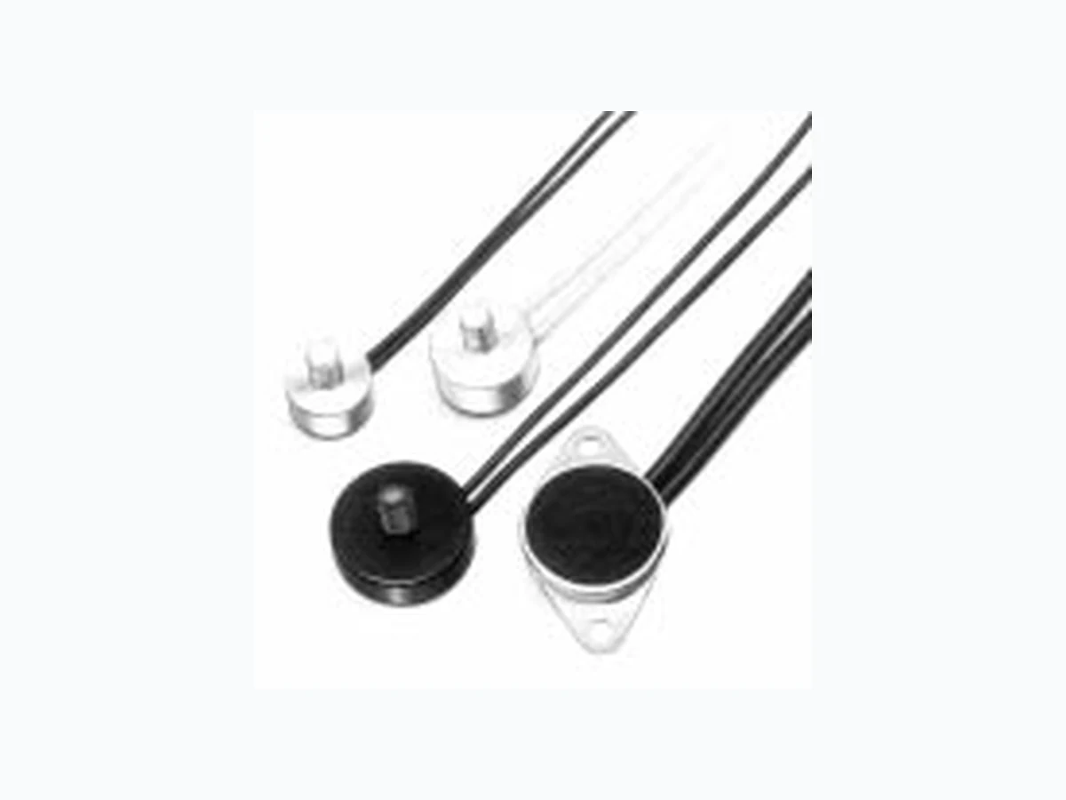
Types E 05, E 11, E 15, E 16, E 18, E 21, E 22, E 23 and E 26 are thermal cutouts.Within limits they can also be used as temperatu- re regulators. A bimetal snap disc with single or double contact opens or closes an electric circuit when reaching a pre-set temperature. Reset follows after a substantial drop in temperature. Heat transfer from all sides results from heat conduction or radiation onto the base of the housing. Standard version: aluminium, black anodised. DIMENSIONS E 05 (Standard) E 11 (Standard) E 18 (Standard) E 21 (Standard)
8415 Mountain Sights Avenue • Montreal (Quebec), H4P 2B8, Canada
Tel: (514) 739-3274 • 1-800-561-7207 • Fax: (514) 739-290 E-mail : sales@cantherm.com • Website: www.cantherm.com
Type E 05 / E23 E 15 / E 16 E 11 / E 18 / E 21 / E 22 / E 26 Voltage rating* 50 – 60 Hz* 250 V 250 V 250 V Current rating cos j = 1,0* 2.0 A 2.0 A 6.3 A Current rating cos j = 0,6* 1.2 A 1.6 A 4.0 A Max. load at cos j = 1,0 without damage 250 V AC 3.0 A 6.3 A 10.0 A 110 V AC 3.5 A 8.0 A 12.0 A 60 V DC 0.6 A 1.0 A 3.0 A 42 V DC 0.8 A 1.2 A 4.2 A 6/12/24 V DC 1.0 A 1.5 A 5.5 A Contact arrangement Switching operations at rated current* Test Class I Test Class I Test Class I Contact resistance < 60 m Ω < 60 mΩ < 60 mΩ Dielectric strength across open contacts 650 Veff 50 Hz 1500 V eff 50 Hz 1000 V eff 50 Hz from +80 °C to from +50 °C to from +50 °C to Response temperature range +150 °C +150 °C +150 °C (353 to 423 K) (323 to 423 K) (323 to 423 K) Standard tolerance ±3 K ±5 K ±10 K ±3 K ±5 K ±10 K ±3 K ±5 K ±10 K Dielectric strength P 300 500 V eff 50/60 Hz housing to earth P 301 1000 V eff 50/60 Hz P 302 2000 V eff 50/60 Hz P 303 2500 V eff 50/60 Hz P 304 4000 V eff 50/60 Hz Max. continuous temperature 150 °C Possible acceleration 3 g (vibration proof) Protection sealed against external elements e. g. dust oil, lacquer, resin et Connections Leads Leads Leads standard 0,25 mm 2 (AWG 24) T 11 normally closed 0.5 mm2 (AWG 22), yellow 0,6 mm 2 (AWG 22) black T 10 normally open 0.25 mm 2 (AWG 24), black yellow Switch element F 11 normally closed T 11 / normally open T 10 B11 TECHNICAL DATA Note: *Approved ratings – Other values on request. RESPONSE TEMPERATURES When selecting the response temperature, the hea- ting and cooling characteristics of the housing should be considered. Temperature testing is carried out with a rate of rise 0.1 °C/min. For cutout types E 05, E 11 and E 18 with response temperatures under 71 °C, the published electrical loading should be reduced by upto 50 %, as these types are current sensitive. Close tolerances on the response temperature or reset temperature, as well as smaller differentials are all possible on request. Reset differential as standard is between 10 °C and 50 °C. Minimum rate of temperature change 0.1 K/min.
APPLICATIONS
Temperature monitoring, control and signalling in electronic and electrical equipment. Examples: Electronic components such as transistors, thyristors, diodes, triacs Power resistors Heat sinks Printed circuits Amplifiers Projectors Electrical machinery and apparatus Generating sets Heat exchangers Plastic and metal housings INSTALLATION HINTS It is important to ensure good heat transfer to the cu- tout: it should be placed directly onto the heat sour- ce. Housings are voltage-free (except G 800) and can be installed without additional insulation. The cutouts can be attached to metal surfaces or housings and, depending on the exact version, can be screwed, clipped, clamed or soldered on. G 800 version can be positioned direct onto a circuit board. 02-04-01 1000-Y133
G 254 E 18 Ø 16x5 Al black as E 18 but without mounting flange G 700 E 05 SW10x3,7 M4x6 Al black threaded stud mounting G 701 E 05 as E 05 G 800 however only 1 wire connection Ø 1.5 G 702 E 05 Ø 12x3,5 M4x6 CuZn threaded stud mounting G 703 E 11 Ø 16x4,8 M4x6 Al black threaded stud with solid wire leads G 707 E 11 Ø 15,7x4,4 M5x6 CuZn central fixing G 711 E 11 as G 703 but with leads G 714 E 21 SW12x4,8 M4x5 CuZn threaded stud G 716 E 21 as G 703 but with 2.8x0.5 tabs G 718 E 11 SW 16x4,8 M4x10 Al black threaded stud and leads G 722 E 18 as E 18 but with narrow flange G 723 E 18 as E 18 but with 2.8x0.5 tabs G 724 E 18 as E 18 but with narrow flange and 2,8x0,5 tabs G 726 E 11 Ø 16x4,8 M4x6 Al black threaded stud and leads E 05 G 800 E 11 tinned Cu lead wires E 21 02-04-01 1000-Y133
Quality Type temperature Version
100 E 11 125 °C ±10 K G 703
Leads or single wire from 0,25 mm 2 to 1,0 mm2, Lengths from 40 mm to 10 000 mm with or with- out stripped ends. Leads fitted with DIN push-on terminations or crimp connectors. Freon or oil re- sistant leads, or PTFE, PVF 2, Nomex or Silicone leads available from stock. IMPORTANT Leads are specified according to insulation class and dielectric strength. MARKING Response temperature in clear text (5 °C steps). Normally closed = blue (epoxy) Normally open = red (epoxy) Special markings available on request. APPROVALS Life expectancy, nominal voltage and current ra- tings according to VDE 0631 or EN 60730. Fur- ther approvals – Information on request. STANDARD QUALITY Production item testing Voltage test, Switch function test, Nominal switching temperature.
ORDERING INFORMATION
We reserve the right to change specifications without prior notice. Tel: (514) 739-3274 • 1-800-561-7207 • Fax: (514) 739-290 E-mail : sales@cantherm.com • Website: www.cantherm.com