
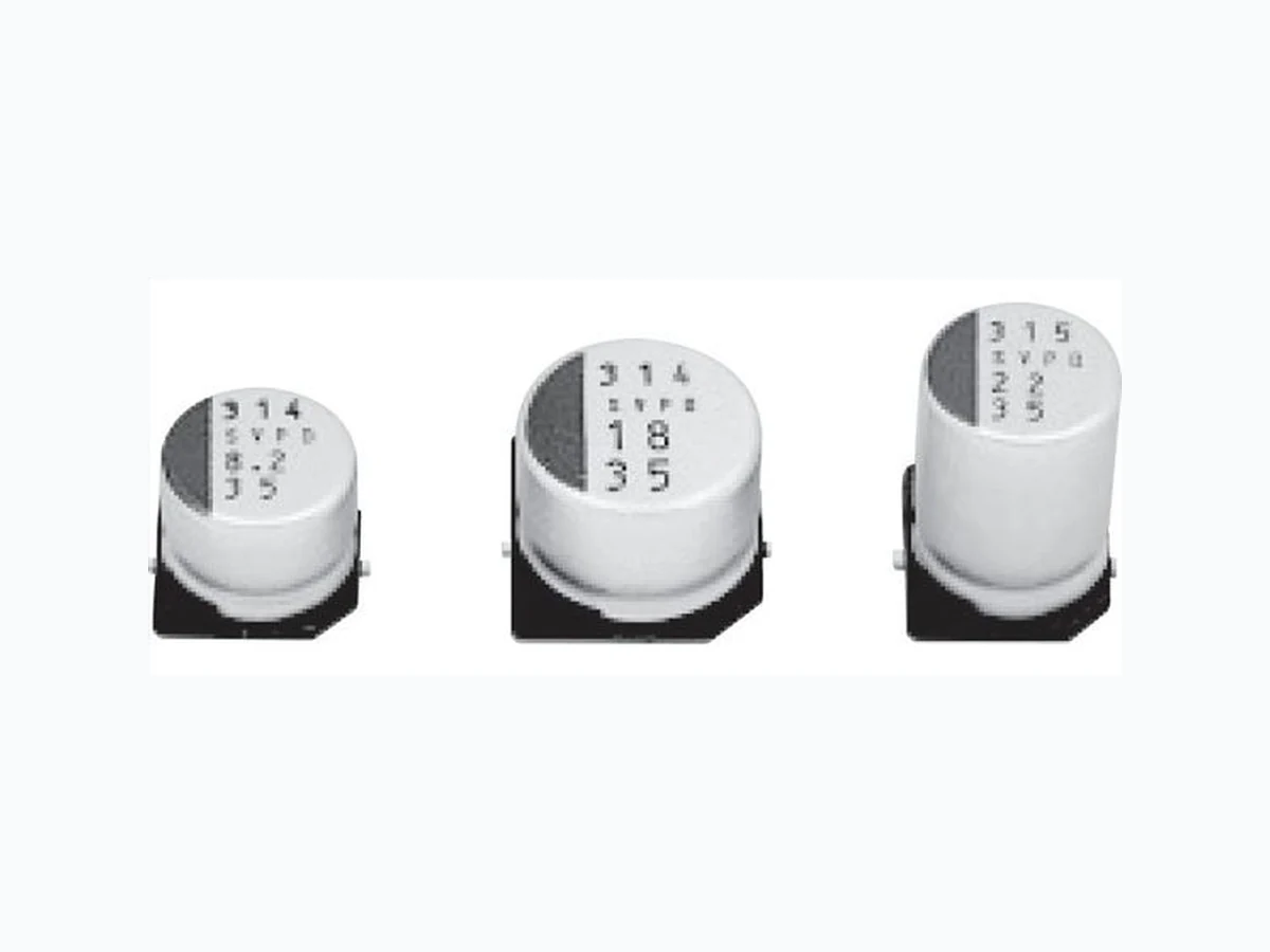
SVPD VISHAY
Document overview
- Manufacturer or author: Provided By www.digicamel.com(FREE DATASHEET DOWNLOAD SITE)
- PDF pages: 13
Technical content
www.vishay.com Vishay OS-CON Revision: 03-Aug-12 1 Document Number: 90022 For technical questions, contact: aluminumcaps4@vishay.com THIS DOCUMENT IS SUBJECT TO CHANGE WITHOUT NOTICE. THE PRODUCTS DESCRIBED HEREIN AND THIS DOCUMENT ARE SUBJECT TO SPECIFIC DISCLAIMERS, SET FORTH AT www.vishay.com/doc?91000 SMD Aluminum Solid Capacitors with Conductive Polymer
FEATURES
- New OS-CON 94SVPD series provides improved characteristics with up to 125 °C temperature capability and 35 V maximum voltage rating in a SMD package
- Improved damp heat (steady state) 85 °C x 85 % RH performance
- Suitable for use in smoothing circuits of vehicle-mounted equipment, industrial equipment, etc.
- This product can support lead (Pb)-free reflow (2)
- Material categorization: For definitions of compliance please see www.vishay.com/doc?99912 Notes (1) If any doubt arises, measure the current after applying voltage (voltage treatment). Voltage treatment: The rated voltage is ap plied (10 V to 35 V) for 120 min at 125 ºC. (2) Refer to “Recommended Reflow Profile” for maximum temperatures. QUICK REFERENCE DATA DESCRIPTION CONDITIONS VALUE Operating temperature range - - 55 °C to + 125 °C Capacitance tolerance 120 Hz M: ± 20 % Tangent of loss angle (tan ) 120 Hz values in Electrical Data and Ordering Information table Leakage current (μA/2 min) (or less) (1) After 2 min values in Electrical Data and Ordering Information table ESR - values in Electrical Data and Ordering Information table Characteristics of impedance ratio at high and low temperature 100 kHz, + 20 °C - 55 °C Z/Z 20 °C 0.75 to 1.25 + 125 °C Z/Z 20 °C 0.75 to 1.0 Endurance + 125 °C, 2000 h rated voltage applied C/C Within ± 20 % tan 2 x or < than an initial standard ESR 2 x or < than an initial standard Leakage current Below an initial standard Damp heat (steady state) + 85 °C, 85 % to 90 % RH, 1000 h rated voltage applied C/C Within ± 20 % tan 2 x or < than an initial standard ESR 2 x or < than an initial standard Leakage current Below an initial standard Solder heat resistance (2) (VPS) (230 °C x 75 s) C/C Within ± 10 % tan 1.3 x or < than an initial standard ESR 1.3 x or < than an initial standard Leakage current Below an initial standard (after voltage procesing) DIMENSIONS in millimeters Ø D L P R C W H 003 SVPD Series Rated capacitance Rated voltage C6 size is PD E7, F8, E12, F12 size is SVPD Polarity marking (Cathode) Case No. 0.2 max. (+)
www.vishay.com Vishay OS-CON Revision: 03-Aug-12 2 Document Number: 90022 For technical questions, contact: aluminumcaps4@vishay.com THIS DOCUMENT IS SUBJECT TO CHANGE WITHOUT NOTICE. THE PRODUCTS DESCRIBED HEREIN AND THIS DOCUMENT ARE SUBJECT TO SPECIFIC DISCLAIMERS, SET FORTH AT www.vishay.com/doc?91000 Notes (1) Capacitance tolerance: M ± 20 % (2) After 2 min (3) Tx: Ambient temperature CASE CODE LIST CAPACITANCE (μF) RATED VOLTAGE (SURGE AT 125 °C) 10.0 (11.5) 16.0 (18.4) 25.0 (29.0) 35.0 (40.0) 8.2 E7 10 C6 18 F8
22 E7 E12
47 E12 F12
82 E7 F12
RECOMMENDED LAND PATTERN DIMENSIONS (in millimeters) SIZE CODE a b c C6 2.1 9.1 1.6 E7 2.8 11.1 1.9 F8 4.3 13.1 1.9 E12 2.8 11.1 1.9 F12 4.3 13.1 1.9 FREQUENCY COEFFICIENT FOR RIPPLE CURRENT FREQUENCY 120 Hz f < 1 kHz 1 kHz f < 10 kHz 10 kHz f < 100 kHz 100 kHz f < 500 kHz COEFFICIENT 0.05 0.3 0.7 1 ELECTRICAL DATA AND ORDERING INFORMATION UR (V) CR (μF) CASE CODE MAX. ESR (100 kHz TO 300 kHz) (m) RATED RIPPLE CURRENT ALLOWABLE RIPPLE CURRENT MAX. TANGENT OF LOSS ANGLE MAX. LEAKAGE CURRENT (μA) (2) PART NUMBER (1)100 kHz (mA) (3) 105 °C < Tx 125 °C Tx 105 °C 10 56 C6 45 538 1700 0.12 112 94SVPD566X0010C6 16 82 E7 40 670 2120 0.12 262 94SVPD826X0016E7 10 C6 65 474 1500 0.10 50 94SVPD106X0025C6 22 E7 48 580 1835 0.10 110 94SVPD226X0025E7 39 F8 45 664 2100 0.10 195 94SVPD396X0025F8 47 E12 30 943 2980 0.12 235 94SVPD476X0025E12 82 F12 28 1202 3800 0.12 410 94SVPD826X0025F12 8.2 E7 70 400 1300 0.10 57 94SVPD825X0035E7 18 F8 60 550 1800 0.10 126 94SVPD186X0035F8 22 E12 50 700 2300 0.12 154 94SVPD226X0035E12 47 F12 30 1150 3650 0.12 329 94SVPD476X0035F12 a b c
www.vishay.com Vishay OS-CON Revision: 03-Aug-12 3 Document Number: 90022 For technical questions, contact: aluminumcaps4@vishay.com THIS DOCUMENT IS SUBJECT TO CHANGE WITHOUT NOTICE. THE PRODUCTS DESCRIBED HEREIN AND THIS DOCUMENT ARE SUBJECT TO SPECIFIC DISCLAIMERS, SET FORTH AT www.vishay.com/doc?91000 FREQUENCY CHARACTERISTICS FREQUENCY (kHz) 0.12 0.5 1 10 100 500 1000 5000 10 000 94SVPD106X0025C6 94SVPD106X0025C6 94SVPD186X0035F8 94SVPD186X0035F8 94SVPD476X0035F12 94SVPD476X0035F12 94SVPD826X0025F12 94SVPD826X0025F12 0.001 0.01 0.1 100 1000 0.1 1 10 100 1000 10 000 Frequency (kHz) ESR, Impedance (Ω) Curve 1: 94SVPD476X0035F12 Impedance (Ω) Curve 2: 94SVPD476X0035F12 ESR (Ω) Curve 3: 94SVPD186X0035F8 Impedance (Ω) Curve 4: 94SVPD186X0035F8 ESR (Ω) Curve 5: 94SVPD106X0025C6 Impedance (Ω) Curve 6: 94SVPD106X0025C6 ESR (Ω) Curve 7: 94SVPD826X0025F12 Impedance (Ω) Curve 8: 94SVPD826X0025F12 ESR (Ω)
www.vishay.com Vishay OS-CON Revision: 03-Aug-12 4 Document Number: 90022 For technical questions, contact: aluminumcaps4@vishay.com THIS DOCUMENT IS SUBJECT TO CHANGE WITHOUT NOTICE. THE PRODUCTS DESCRIBED HEREIN AND THIS DOCUMENT ARE SUBJECT TO SPECIFIC DISCLAIMERS, SET FORTH AT www.vishay.com/doc?91000 Notes
- n = 30 pieces TYPICAL PARAMETERS MODEL TEST ITEM TEST TEMPERATURE APPLIED VOLTAGE LOT. NUMBER 94SVPD106X0025C6 Endurance (after V.P.S. test) 125 °C 25 V 7130A2714 Change in capacitance (120 Hz) - 40 - 30 - 20 - 10 0 2000 Time (h) Δ (%) Max. Min. Av. 0.01 0.02 0.03 0.04 0.05 0.06 0.07 0.08 0.09 0.10 0.11 0.12 0 2000 Time (h) Tangent of loss angle Tangent of loss angle (120 Hz) Min. Max. Av. 0 2000 TIME (h) Min. ESR (100 kHz) 100 120 140 160 180 200 ESR (mΩ) Max.Av. Leakage current (25 V, 60 s) 0.01 0.1 100 1000 10 000 0 2000 Time (h) Leakage current (µA) Min. Max. Av.
www.vishay.com Vishay OS-CON Revision: 03-Aug-12 5 Document Number: 90022 For technical questions, contact: aluminumcaps4@vishay.com THIS DOCUMENT IS SUBJECT TO CHANGE WITHOUT NOTICE. THE PRODUCTS DESCRIBED HEREIN AND THIS DOCUMENT ARE SUBJECT TO SPECIFIC DISCLAIMERS, SET FORTH AT www.vishay.com/doc?91000 Notes
- n = 30 pieces TYPICAL PARAMETERS MODEL TEST ITEM TEST TEMPERATURE APPLIED VOLTAGE LOT. NUMBER 94SVPD186X0035F8 Endurance (after V.P.S. test) 125 °C 35 V 6517A3254 Change in capacitance (120 Hz) - 40 - 30 - 20 - 10 0 2000 Time (h) Δ (%) Max. Min. Av. 0.01 0.02 0.03 0.04 0.05 0.06 0.07 0.08 0.09 0.10 0.11 0.12 0 2000 Time (h) Tangent of loss angle Tangent of loss angle (120 Hz) Min. Max. Av. 0 2000 Time (h) ESR (100 kHz) 100 120 140 160 180 200 ESR (mΩ) Min. Max.Av. Leakage current (35 V, 60 s) 0.01 0.1 100 1000 10 000 0 2000 Time (h) Leakage current (µA) Min. Max. Av.
www.vishay.com Vishay OS-CON Revision: 03-Aug-12 6 Document Number: 90022 For technical questions, contact: aluminumcaps4@vishay.com THIS DOCUMENT IS SUBJECT TO CHANGE WITHOUT NOTICE. THE PRODUCTS DESCRIBED HEREIN AND THIS DOCUMENT ARE SUBJECT TO SPECIFIC DISCLAIMERS, SET FORTH AT www.vishay.com/doc?91000 Notes
- n = 30 pieces TYPICAL PARAMETERS MODEL TEST ITEM TEST TEMPERATURE APPLIED VOLTAGE LOT. NUMBER 94SVPD476X0035F12 Endurance (after V.P.S. test) 125 °C 35 V 7209A6544 Change in capacitance (120 Hz) - 40 - 30 - 20 - 10 0 2000 Time (h) Δ (%) Min. Max. Av. 0.01 0.02 0.03 0.04 0.05 0.06 0.07 0.08 0.09 0.10 0.11 0.12 0 2000 Time (h) Tangent of loss angle Tangent of loss angle (120 Hz) Min. Max. Av. 0 2000 Time (h) ESR (100 kHz) 100 120 140 160 180 200 ESR (mΩ) Min. Max. Av. Leakage current (35 V, 60 s) 0.01 0.1 100 1000 10 000 0 2000 Time (h) Leakage current (µA) Min. Max. Av.
www.vishay.com Vishay OS-CON Revision: 03-Aug-12 7 Document Number: 90022 For technical questions, contact: aluminumcaps4@vishay.com THIS DOCUMENT IS SUBJECT TO CHANGE WITHOUT NOTICE. THE PRODUCTS DESCRIBED HEREIN AND THIS DOCUMENT ARE SUBJECT TO SPECIFIC DISCLAIMERS, SET FORTH AT www.vishay.com/doc?91000 Notes
- n = 30 pieces TYPICAL PARAMETERS MODEL TEST ITEM TEST TEMPERATURE APPLIED VOLTAGE LOT. NUMBER 94SVPD826X0025F12 Endurance (after V.P.S. test) 125 °C 25 V 7527A6544 Change in capacitance (120 Hz) - 40 - 30 - 20 - 10 0 2000 Time (h) Δ (%) Min. Max. Av. 0.01 0.02 0.03 0.04 0.05 0.06 0.07 0.08 0.09 0.10 0.11 0.12 0 2000 Time (h) Tangent of loss angle Tangent of loss angle (120 Hz) Min. Max. Av. 0 2000 Time (h) ESR (100 kHz) 100 120 140 160 180 200 ESR (mΩ) Min. Max. Av. Leakage current (25 V, 60 s) 0.01 0.1 100 1000 10 000 0 2000 Time (h) Leakage current (µA) Min. Max.Av.
www.vishay.com Vishay OS-CON Revision: 03-Aug-12 8 Document Number: 90022 For technical questions, contact: aluminumcaps4@vishay.com THIS DOCUMENT IS SUBJECT TO CHANGE WITHOUT NOTICE. THE PRODUCTS DESCRIBED HEREIN AND THIS DOCUMENT ARE SUBJECT TO SPECIFIC DISCLAIMERS, SET FORTH AT www.vishay.com/doc?91000 Notes
- n = 30 pieces TYPICAL PARAMETERS MODEL TEST ITEM TEST TEMPERATURE APPLIED VOLTAGE TEST HUMIDITY LOT. NUMBER 94SVPD106X0025C6 Damp heat (steady state) (after V.P.S. test) 85 °C 25 V 85 % 7530A2714 Change in capacitance (120 Hz) - 40 - 30 - 20 - 10 0 1000 Time (h) Δ (%) Min. Max. Av. 0.01 0.02 0.03 0.04 0.05 0.06 0.07 0.08 0.09 0.10 0.11 0.12 0 1000 Time (h) Tangent of loss angle Tangent of loss angle (120 Hz) Max. Min. Av. 0 1000 Time (h) ESR (100 kHz) 100 120 140 160 180 200 ESR (mΩ) Min. Max. Av. Leakage current (25 V, 60 s) 0.01 0.1 100 1000 10 000 0 1000 Time (h) Leakage current (µA) Min. Max. Av.
www.vishay.com Vishay OS-CON Revision: 03-Aug-12 9 Document Number: 90022 For technical questions, contact: aluminumcaps4@vishay.com THIS DOCUMENT IS SUBJECT TO CHANGE WITHOUT NOTICE. THE PRODUCTS DESCRIBED HEREIN AND THIS DOCUMENT ARE SUBJECT TO SPECIFIC DISCLAIMERS, SET FORTH AT www.vishay.com/doc?91000 Notes
- n = 30 pieces TYPICAL PARAMETERS MODEL TEST ITEM TEST TEMPERATURE APPLIED VOLTAGE TEST HUMIDITY LOT. NUMBER 94SVPD186X0035F8 Damp heat (steady state) (after V.P.S. test) 85 °C 35 V 85 % 6517A3254 Change in capacitance (120 Hz) - 40 - 30 - 20 - 10 0 1000 Time (h) Δ (%) Min. Max.Av. 0.01 0.02 0.03 0.04 0.05 0.06 0.07 0.08 0.09 0.10 0.11 0.12 0 1000 Time (h) Tangent of loss angle Tangent of loss angle (120 Hz) Max. Min. Av. 0 1000 Time (h) ESR (100 kHz) 100 120 140 160 180 200 ESR (mΩ) Max. Min. Av. Leakage current (35 V, 60 s) 0.01 0.1 100 1000 10 000 0 1000 Time (h) Leakage current (µA) Min. Max. Av.
www.vishay.com Vishay OS-CON Revision: 03-Aug-12 10 Document Number: 90022 For technical questions, contact: aluminumcaps4@vishay.com THIS DOCUMENT IS SUBJECT TO CHANGE WITHOUT NOTICE. THE PRODUCTS DESCRIBED HEREIN AND THIS DOCUMENT ARE SUBJECT TO SPECIFIC DISCLAIMERS, SET FORTH AT www.vishay.com/doc?91000 Notes
- n = 30 pieces TYPICAL PARAMETERS MODEL TEST ITEM TEST TEMPERATURE APPLIED VOLTAGE TEST HUMIDITY LOT. NUMBER 94SVPD476X0035F12 Damp heat (steady state) (after V.P.S. test) 85 °C 35 V 85 % 7209A6544 Change in capacitance (120 Hz) - 40 - 30 - 20 - 10 0 1000 Time (h) Δ (%) Max. Min. Av. 0.01 0.02 0.03 0.04 0.05 0.06 0.07 0.08 0.09 0.10 0.11 0.12 0 1000 Time (h) Tangent of loss angle Tangent of loss angle (120 Hz) Max. Min. Av. 0 1000 Time (h) ESR (100 kHz) 100 120 140 160 180 200 ESR (mΩ) Max. Min. Av. Leakage current (35 V, 60 s) 0.01 0.1 100 1000 10 000 0 1000 Time (h) Leakage current (µA) Min. Max. Av.
www.vishay.com Vishay OS-CON Revision: 03-Aug-12 11 Document Number: 90022 For technical questions, contact: aluminumcaps4@vishay.com THIS DOCUMENT IS SUBJECT TO CHANGE WITHOUT NOTICE. THE PRODUCTS DESCRIBED HEREIN AND THIS DOCUMENT ARE SUBJECT TO SPECIFIC DISCLAIMERS, SET FORTH AT www.vishay.com/doc?91000 Notes
- n = 30 pieces TYPICAL PARAMETERS MODEL TEST ITEM TEST TEMPERATURE APPLIED VOLTAGE TEST HUMIDITY LOT. NUMBER 94SVPD826X0025F12 Damp heat (steady state) (after V.P.S. test) 85 °C 25 V 85 % 6806A6724 Change in capacitance (120 Hz) - 40 - 30 - 20 - 10 0 1000 Time (h) Δ (%) Max. Min. Av. 0.01 0.02 0.03 0.04 0.05 0.06 0.07 0.08 0.09 0.10 0.11 0.12 0 1000 Time (h) Tangent of loss angle Tangent of loss angle (120 Hz) Max. Min. Av. 0 1000 Time (h) ESR (100 kHz) 100 120 140 160 180 200 ESR (mΩ) Max. Min. Av. Leakage current (25 V, 60 s) 0.01 0.1 100 1000 10 000 0 1000 Time (h) Leakage current (µA) Min. Max. Av.
www.vishay.com Vishay OS-CON Revision: 03-Aug-12 12 Document Number: 90022 For technical questions, contact: aluminumcaps4@vishay.com THIS DOCUMENT IS SUBJECT TO CHANGE WITHOUT NOTICE. THE PRODUCTS DESCRIBED HEREIN AND THIS DOCUMENT ARE SUBJECT TO SPECIFIC DISCLAIMERS, SET FORTH AT www.vishay.com/doc?91000 RECOMMENDED REFLOW PROFILE Vishay OS-CON has different characteristic s against soldering heat from conventional aluminum electrolytic capacitors or tantalum capacitors because of its unique materials and structure. Please note the following points on soldering of Vishay OS-CON 94SVPD series to draw out the best performance. Note
- All temperatures are measured on the topside of the Al-can and terminal surface. Attention: Reflow soldering may reduce the capacitanc e of products before or after soldering ev en if soldering conditions stipulated in Recommended Reflow Condition are met. Though the actual reflow conditions are subject to change depending on the kind of reflow soldering method, please be aware that the peak temper ature at the top of Al-case and electrode terminals should not exceed peak temperature. Particular notice should be given to the time that Vishay OS-CON is heated at 200 °C or higher during reflow. Be aware that soldering considerably deviating from these conditions will cause problems such as a 50 % reduction in capacitance, and a considerable increase in leakage current. The leakage current value may increase (from a few μA to a few mA) even within the above conditions. When the Vishay OS-CON is used in a DC circuit, the leakage current will decrease gradually through self-recovery after voltage is applied. If your reflow profile (reflow temperature, number of reflows, etc.) deviates from the above conditions for mounting the 94SVPD series, please consult with Vishay OS-CON. ITEM 94SVPD SERIES Peak temperature (max.) 250 °C 260 °C Preheat 150 °C to 180 °C 90 ± 30 s 200 °C over time (max.) 60 s 60 s 220 °C over time (max.) 50 s 50 s 230 °C over time (max.) 40 s 40 s Reflow number Twice or less Only 1 time Surface of external case/terminal (°C) 300 250 200 150 100 0 30 60 90 120 150 180 210 240 Preheating 150 °C to 180 °C Duration at 230 °C or higher Peak temperature Duration at 200 °C or higher Duration at 220 °C or higher
www.vishay.com Vishay Revision: 01-Jan-2021 1 Document Number: 91000 Disclaimer ALL PRODUCT, PRODUCT SPECIFICATIONS AND DATA AR E SUBJECT TO CHANGE WITH OUT NOTICE TO IMPROVE RELIABILITY, FUNCTION OR DESIGN OR OTHERWISE. Vishay Intertechnology, Inc., its affiliates, agents, and employee s, and all persons acting on it s or their behalf (collectivel y, “Vishay”), disclaim any and all liability for any errors, inaccuracies or incompleteness contained in any datasheet or in any other disclosure relating to any product. Vishay makes no warranty, representation or guarantee regarding the suitability of the products for any particular purpose or the continuing production of any product. To the maximum extent permitted by applicable law, Vishay disclaims (i) any and all liability arising out of the application or use of any product , (ii) any and all liability, including without limitation specia l, consequential or incidental damages, and (iii) any and all implied warranties, incl uding warranties of fitness for particular purpose, non-infringement and merchantability. Statements regarding the suitability of products for certain types of applicatio ns are based on Vishay’s knowledge of typical requirements that are often placed on Vishay products in generic applications. Such statements are not binding statements about the suitability of products for a particular applic ation. It is the customer’s responsibility to validate tha t a particular product with the prope rties described in the product sp ecification is suitable for use in a particular application. Parameters provided in datasheets and / or specifications may vary in different ap plications and performance may vary over time. All operating parameters, including typical parameters, must be validated for each customer application by the customer’s technical experts. Product specifications do not expand or otherwise modify Vishay’s term s and conditions of purchase, including but not limited to the warranty expressed therein. Except as expressly indicated in writing, Vishay products are not designed for use in medical, life-saving, or life-sustaining applications or for any other application in which the failure of the Vishay product could result in personal injury or death. Customers using or selling Vishay product s not expressly indicated for use in such applications do so at their own risk. Please contact authorized Vishay personnel to obtain writ ten terms and conditions rega rding products designed for such applications. No license, express or implied, by estoppel or otherwise, to any intellectual property rights is gr anted by this document or by any conduct of Vishay. Product names and markings noted herein may be trademarks of their respective owners. © 2021 VISHAY INTERTECHNOLOGY, INC. ALL RIGHTS RESERVED