

 Download PDF
DZT2222A
Document overview
- PDF pages: 8
Technical content
Page 1
Features
BVCEO > 40V Epitaxial Planar Die Construction Ideally Suited for Automated Assembly Processes Complementary PNP Type Available: DIODES™ DZT2907A Totally Lead-Free & Fully RoHS Compliant (Notes 1 & 2) Halogen and Antimony Free. “Green” Device (Note 3) For automotive applications requiring specific change control (i.e. parts qualified to AEC-Q100/101/104/200, PPAP capable, and manufactured in IATF 16949 certified facilities), please contact us or your local Diodes representative. https://www.diodes.com/quality/product-definitions/
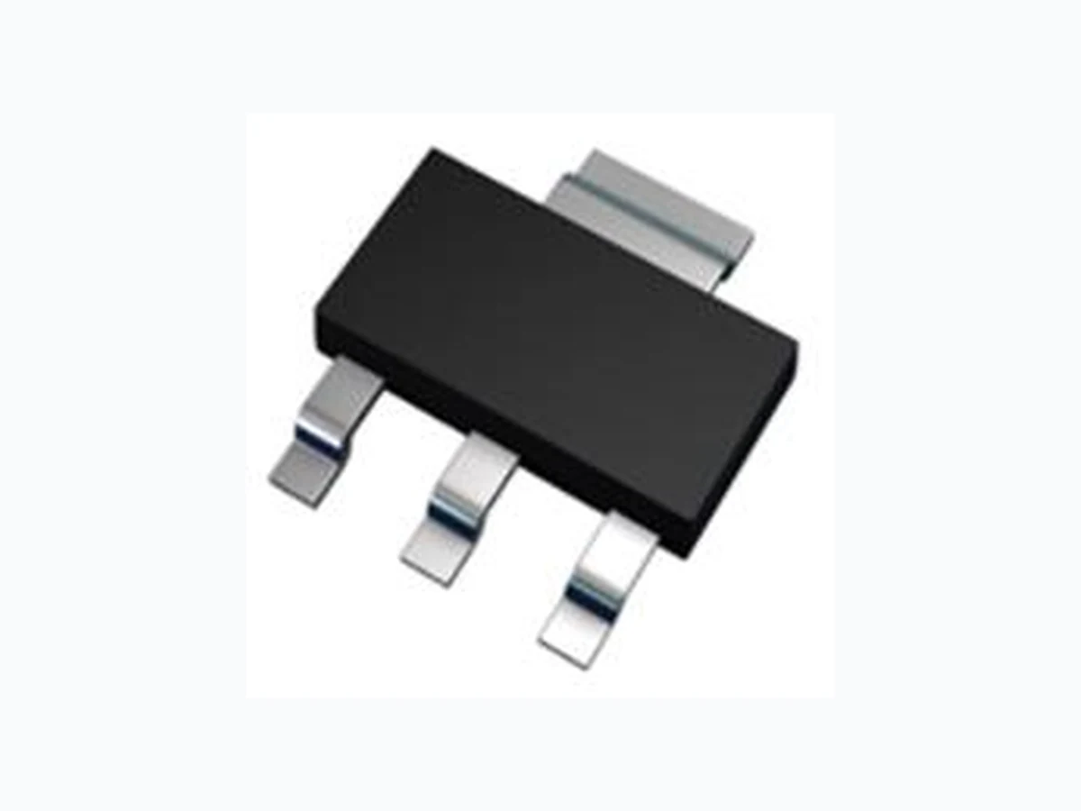
SOT223
B
Top View
40V NPN SMALL SIGNAL TRANSISTOR IN SOT223
Mechanical Data
Package: SOT223 Package Material: Molded Plastic. “Green” Molding Compound. UL Flammability Rating 94V-0 Moisture Sensitivity: Level 1 per J-STD-020 Terminals: Finish - Matte Tin Plated Leads, Solderable per MIL-STD-202, Method 208 Weight: 0.112 grams (Approximate)
Applications
Medium power switching & amplification
C
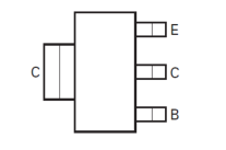
E
Top View
Device Symbol
Pin-Out
Ordering Information (Note 4)
| Part Number | Package | Marking | Reel Size (inches) | Tape Width (mm) | Packing | |
| Qty. | Carrier | |||||
| DZT2222A-13 | SOT223 | K1P | 13 | 12 | 2,500 | Reel |
Notes: 1. No purposely added lead. Fully EU Directive 2002/95/EC (RoHS), 2011/65/EU (RoHS 2) & 2015/863/EU (RoHS 3) compliant. 2. See https://www.diodes.com/quality/lead-free/ for more information about Diodes Incorporated’s definitions of Halogen- and Antimony-free, "Green" and Lead-free. 3. Halogen- and Antimony-free "Green” products are defined as those which contain <900ppm bromine, <900ppm chlorine (<1500ppm total Br + Cl) and <1000ppm antimony compounds. 4. For packaging details, go to our website at https://www.diodes.com/design/support/packaging/diodes-packaging/.
Marking Information
SOT223
(Top View)
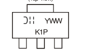
K1P = Product Type Marking Code YWW = Date Code Marking Y or Y = Last Digit of Year (ex: 3 = 2023) WW = Week Code (01 to 52)
1 of 8
Page 2
Absolute Maximum Ratings (@TA = +25°C, unless otherwise specified.)
| Characteristic | Symbol | Value | Unit |
| Collector-Base Voltage | VCBO | 75 | V |
| Collector-Emitter Voltage | VCEO | 40 | V |
| Emitter-Base Voltage | VEBO | 6 | V |
| Collector Current | IC | 600 | mA |
Thermal Characteristics (@TA = +25°C, unless otherwise specified.)
| Characteristic | Symbol | Value | Unit |
| Power Dissipation (Note 5) | PD | 0.83 | W |
| Thermal Resistance, Junction to Ambient Air (Note 5) | RJA | 150 | C/W |
| Thermal Resistance, Junction to Case (Note 5) | RJC | 53 | C/W |
| Operating and Storage Temperature Range | TJ, TSTG | -55 to +150 | C |
- For a device mounted on minimum recommended pad (MRP) layout that is on a single-sided 1.6mm FR4 PCB; device is measured under still air Note: conditions whilst operating in a steady-state.
2 of 8
Page 3
Thermal Characteristics and Derating Information
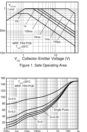
Pulse Width (s)
Transient Thermal Impedance
Figure 3. Transient Thermal Impedance
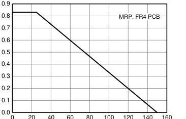
Temperature (°C)
Derating Curve
Figure 2. Derating Curve
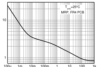
Pulse Width (s)
Pulse Power Dissipation
Figure 4. Pulse Power Dissipation
3 of 8
Page 4
Electrical Characteristics (@TA = +25°C, unless otherwise specified.)
| Characteristic | Symbol | Min | Typ | Max | Unit | Test Conditions |
|---|---|---|---|---|---|---|
| OFF CHARACTERISTICS (Note 6) | ||||||
| Collector-Base Breakdown Voltage | BVCBO | 75 | 125 | | V | IC = 100μA |
| Collector-Emitter Breakdown Voltage | BVCEO | 40 | 59 | | V | IC = 10mA |
| Emitter-Base Breakdown Voltage | BVEBO | 6 | 7.5 | | V | IE = 100μA |
| Collector-Base Cut-Off Current | ICBO | | 2 | 10 | nA | VCB = 50V |
| | | 10 | μA | VCB = 50V, TA = +150°C | ||
| Emitter-Base Cut-Off Current | IEBO | | 2 | 10 | nA | VEB = 3V |
| Collector-Emitter Cut-Off Current | ICEX | | | 10 | nA | VCE = 60V, VEB(off) = 3V |
| ON CHARACTERISTICS (Note 6) | ||||||
| Collector-Emitter Saturation Voltage | VCE(sat) | | 0.11 | 0.3 | V | IC = 150mA, IB = 15mA |
| | 0.31 | 1.0 | V | IC = 500mA, IB = 50mA | ||
| Base-Emitter Saturation Voltage | VBE(sat) | 0.6 | 0.87 | 1.2 | V | IC = 150mA, IB = 15mA |
| | 1.04 | 2.0 | V | IC = 500mA, IB = 50mA | ||
| DC Current Gain | hFE | 35 | 2.12 | | | IC = 0.1mA, VCE = 10V |
| 50 | 263 | | IC = 1mA, VCE = 10V | |||
| 75 | 223 | | IC = 10mA, VCE = 10V | |||
| 35 | 131 | | IC = 10mA, VCE = 10V, TA = -55°C | |||
| 100 | 229 | 300 | IC = 150mA, VCE = 10V | |||
| 50 | 123 | | IC = 150mA, VCE = 1V | |||
| 40 | 67 | | IC = 500mA, VCE = 10V | |||
| SMALL SIGNAL CHARACTERISTICS | ||||||
| Transition Frequency | fT | 300 | | | MHz | IC = 20mA, VCE = 20V, f = 100MHz |
| Output Capacitance | Cobo | | | 8 | pF | VCB = 10V, f = 1MHz |
| Input Capacitance | Cibo | | | 25 | pF | VEB = 0.5V, f = 1MHz |
| SWITCHING CHARACTERISTICS | ||||||
| Delay Time | td | | 3.9 | 10 | ns | VCE = 30V, VEB(off) = 0.5V, IC = 150mA, IB1 = 15mA |
| Rise Time | tr | | 6.4 | 25 | ns | |
| Storage Time | ts | | 188 | 225 | ns | VCE = 30V, IC = 150mA, IB1 = -IB2 = 15mA |
| Fall Time | tf | | 42 | 60 | ns | |
- Measured under pulsed conditions. Pulse width ≤ 300µs. Duty cycle ≤ 2%. Note:
4 of 8
Page 5
Typical Electrical Characteristics (@TA = +25°C, unless otherwise specified.)
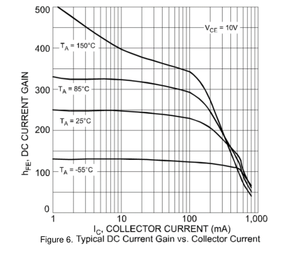
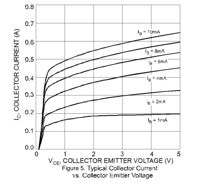
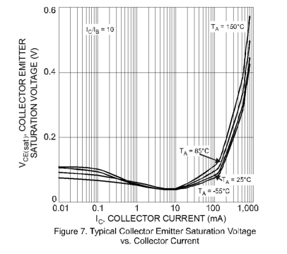
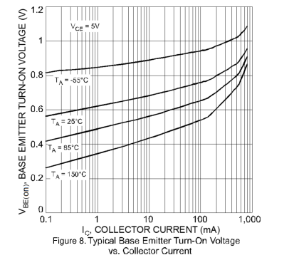
5 of 8
Page 6
Typical Electrical Characteristics (continued)
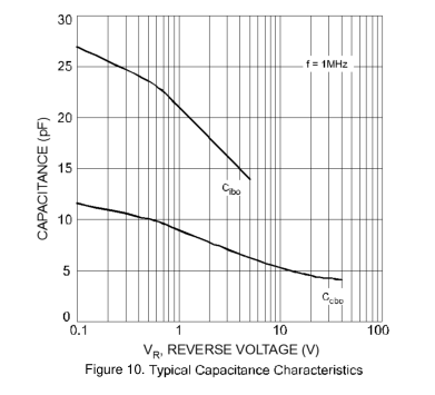
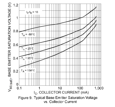
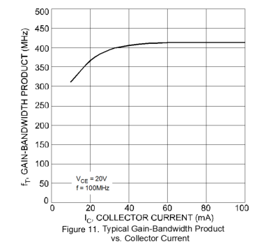
6 of 8
Page 7
Package Outline Dimensions
Please see http://www.diodes.com/package-outlines.html for the latest version.
SOT223
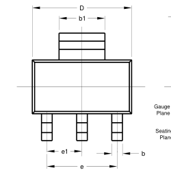
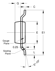
| SOT223 | |||
| Dim | Min | Max | Typ |
| A | 1.55 | 1.65 | 1.60 |
| A1 | 0.010 | 0.15 | 0.05 |
| b | 0.60 | 0.80 | 0.70 |
| b1 | 2.90 | 3.10 | 3.00 |
| C | 0.20 | 0.30 | 0.25 |
| D | 6.45 | 6.55 | 6.50 |
| E | 3.45 | 3.55 | 3.50 |
| E1 | 6.90 | 7.10 | 7.00 |
| e | - | - | 4.60 |
| e1 | - | - | 2.30 |
| L | 0.85 | 1.05 | 0.95 |
| Q | 0.84 | 0.94 | 0.89 |
| All Dimensions in mm | |||
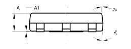
Suggested Pad Layout
Please see http://www.diodes.com/package-outlines.html for the latest version.
SOT223
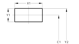
| Dimensions | Value (in mm) |
| C | 2.30 |
| C1 | 6.40 |
| X | 1.20 |
| X1 | 3.30 |
| Y | 1.60 |
| Y1 | 1.60 |
| Y2 | 8.00 |
Y
C X
7 of 8
Page 8
IMPORTANT NOTICE
DIODES INCORPORATED (Diodes) AND ITS SUBSIDIARIES MAKE NO WARRANTY OF ANY KIND, EXPRESS OR IMPLIED, WITH 1. REGARDS TO ANY INFORMATION CONTAINED IN THIS DOCUMENT, INCLUDING, BUT NOT LIMITED TO, THE IMPLIED WARRANTIES OF MERCHANTABILITY, FITNESS FOR A PARTICULAR PURPOSE OR NON-INFRINGEMENT OF THIRD PARTY INTELLECTUAL PROPERTY RIGHTS (AND THEIR EQUIVALENTS UNDER THE LAWS OF ANY JURISDICTION).
The Information contained herein is for informational purpose only and is provided only to illustrate the operation of Diodes’ products 2. described herein and application examples. Diodes does not assume any liability arising out of the application or use of this document or any product described herein. This document is intended for skilled and technically trained engineering customers and users who design with Diodes’ products. Diodes’ products may be used to facilitate safety-related applications; however, in all instances customers and users are responsible for (a) selecting the appropriate Diodes products for their applications, (b) evaluating the suitability of Diodes’ products for their intended applications, (c) ensuring
their applications, which incorporate Diodes’ products, comply the applicable legal and regulatory requirements as well as safety and functionalsafety related standards, and (d) ensuring they design with appropriate safeguards (including testing, validation, quality control techniques, redundancy, malfunction prevention, and appropriate treatment for aging degradation) to minimize the risks associated with their applications.
Diodes assumes no liability for any application-related information, support, assistance or feedback that may be provided by Diodes from 3. time to time. Any customer or user of this document or products described herein will assume all risks and liabilities associated with such use, and will hold Diodes and all companies whose products are represented herein or on Diodes’ websites, harmless against all damages and liabilities.
Products described herein may be covered by one or more United States, international or foreign patents and pending patent applications. 4. Product names and markings noted herein may also be covered by one or more United States, international or foreign trademarks and trademark applications. Diodes does not convey any license under any of its intellectual property rights or the rights of any third parties (including third parties whose products and services may be described in this document or on Diodes’ website) under this document.
Diodes’ products are provided subject to Diodes’ Standard Terms and Conditions of Sale 5. (https://www.diodes.com/about/company/terms-and-conditions/terms-and-conditions-of-sales/) or other applicable terms. This document does not alter or expand the applicable warranties provided by Diodes. Diodes does not warrant or accept any liability whatsoever in respect of any products purchased through unauthorized sales channel.
Diodes’ products and technology may not be used for or incorporated into any products or systems whose manufacture, use or sale is 6. prohibited under any applicable laws and regulations. Should customers or users use Diodes’ products in contravention of any applicable laws or regulations, or for any unintended or unauthorized application, customers and users will (a) be solely responsible for any damages, losses or penalties arising in connection therewith or as a result thereof, and (b) indemnify and hold Diodes and its representatives and agents harmless against any and all claims, damages, expenses, and attorney fees arising out of, directly or indirectly, any claim relating to any noncompliance with
the applicable laws and regulations, as well as any unintended or unauthorized application.
While efforts have been made to ensure the information contained in this document is accurate, complete and current, it may contain 7. technical inaccuracies, omissions and typographical errors. Diodes does not warrant that information contained in this document is error-free and Diodes is under no obligation to update or otherwise correct this information. Notwithstanding the foregoing, Diodes reserves the right to make modifications, enhancements, improvements, corrections or other changes without further notice to this document and any product described herein. This document is written in English but may be translated into multiple languages for reference. Only the English version of this document is the final
and determinative format released by Diodes.
Any unauthorized copying, modification, distribution, transmission, display or other use of this document (or any portion hereof) is 8. prohibited. Diodes assumes no responsibility for any losses incurred by the customers or users or any third parties arising from any such unauthorized use.
- This Notice may be periodically updated with the most recent version available at https://www.diodes.com/about/company/terms-andconditions/important-notice
The Diodes logo is a registered trademark of Diodes Incorporated in the United States and other countries. DIODES is a trademark of Diodes Incorporated in the United States and other countries. All other trademarks are the property of their respective owners. © 2023 Diodes Incorporated. All Rights Reserved.
8 of 8