
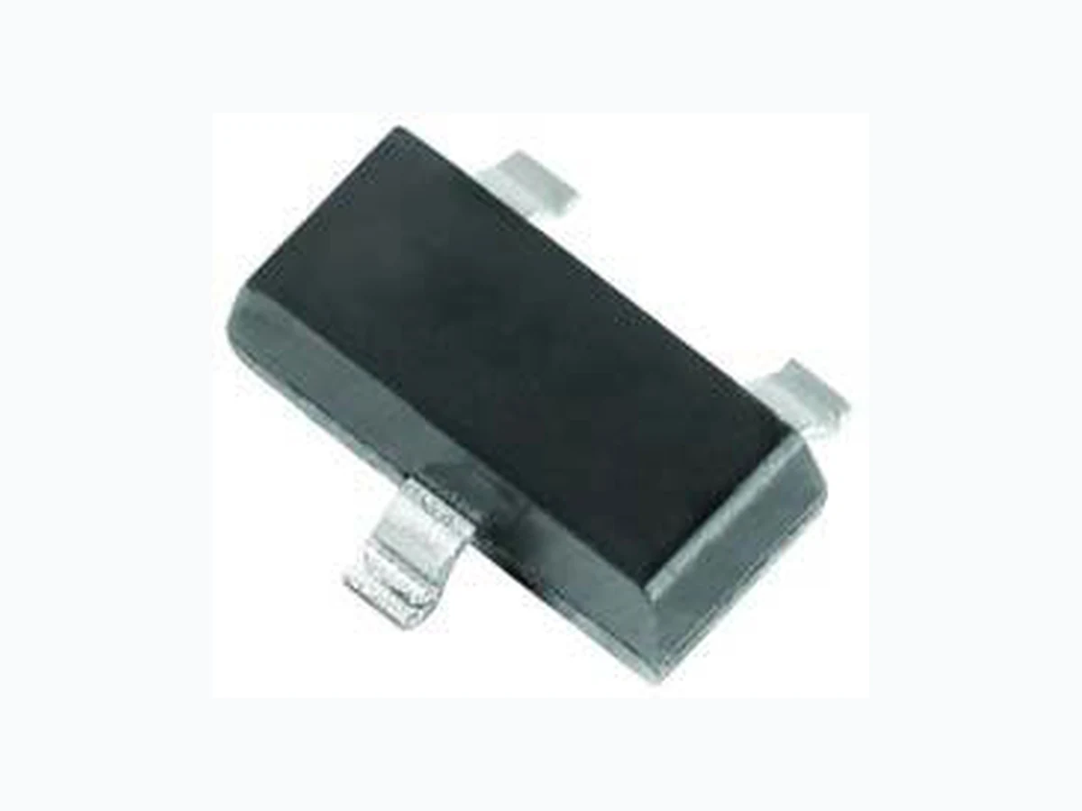
DZ23 VISHAY
Document overview
- Manufacturer or author: Provided By www.digicamel.com(free datasheet download site)
- PDF pages: 7
Technical content
www.vishay.com Vishay Semiconductors Rev. 2.0, 08-Nov-16 1 Document Number: 85765 For technical questions within your region: DiodesAmericas@vishay.com, DiodesAsia@vishay.com, DiodesEurope@vishay.com THIS DOCUMENT IS SUBJECT TO CHANGE WITHOUT NOTICE. THE PRODUCTS DESCRIBED HEREIN AND THIS DOCUMENT ARE SUBJECT TO SPECIFIC DISCLAIMERS, SET FORTH AT www.vishay.com/doc?91000 Small Signal Zener Diodes, Dual
FEATURES
- Dual silicon planar Zener diodes, common cathode
- The Zener voltages are graded according to the international E24 standard. Standard Zener voltage tolerance is ± 5 %.
- The parameters are valid for both diodes in one case. V Z and Rzj of the two diodes in one case is 5 %
- AEC-Q101 qualified available
- ESD capability according to AEC-Q101: Human body model > 8 kV Machine model > 800 V
- Base P/N-E3 - RoHS-compliant, commercial grade
- Base P/N-HE3 - RoHS-compliant, AEC-Q101 qualified
- Material categorization: fo r definitions of compliance please see www.vishay.com/doc?99912 PRIMARY CHARACTERISTICS PARAMETER VALUE UNIT V Z range nom. 2.7 to 51 V Test current IZT 5m A VZ specification Pulse current Int. construction Dual common cathode Available
ORDERING INFORMATION
DEVICE NAME ORDERING CODE TAPED UNITS PER REEL MINIMUM ORDER QUANTITY DZ23-series DZ23C2V7-E3-08 to DZ23C51-E3-08 3000 (8 mm tape on 7" reel) 15 000 DZ23C2V7-HE3-08 to DZ23C51-HE3-08 DZ23C2V7-E3-18 to DZ23C51-E3-18 10 000 (8 mm tape on 13" reel) 10 000 DZ23C2V7-HE3-18 to DZ23C51-HE3-18 PACKAGE PACKAGE NAME WEIGHT MOLDING COMPOUND FLAMMABILITY RATING MOISTURE SENSITIVITY LEVEL SOLDERING CONDITIONS SOT-23 8.8 mg UL 94 V-0 MSL level 1 (according J-STD-020) 260 °C/10 s at terminals ABSOLUTE MAXIMUM RATINGS (Tamb = 25 °C, unless otherwise specified) PARAMETER TEST CONDITION SYMBOL VALUE UNIT Power dissipation Device on fiberglass substrate, see layout on page 6 Ptot 300 mW Thermal resistance, junction to ambient air Device on fiberglass substrate, see layout on page 6 RthJA 420 K/W Junction temperature Tj 150 °C Storage temperature range Tstg -65 to +150 °C Operating temperature range Top -55 to +150 °C Zener current I Z Ptot/VZ mA
www.vishay.com Vishay Semiconductors Rev. 2.0, 08-Nov-16 2 Document Number: 85765 For technical questions within your region: DiodesAmericas@vishay.com, DiodesAsia@vishay.com, DiodesEurope@vishay.com THIS DOCUMENT IS SUBJECT TO CHANGE WITHOUT NOTICE. THE PRODUCTS DESCRIBED HEREIN AND THIS DOCUMENT ARE SUBJECT TO SPECIFIC DISCLAIMERS, SET FORTH AT www.vishay.com/doc?91000 Note (1) Tested with pulses tp = 5 ms ELECTRICAL CHARACTERISTICS (Tamb = 25 °C, unless otherwise specified) PART NUMBER MARKING CODE ZENER VOLTAGE RANGE (1) TEST CURRENT REVERSE VOLTAGE DYNAMIC RESISTANCE f = 1 kHz TEMPERATURE COEFFICIENT OF ZENER VOLTAGE VZ at IZT1 IZT1 IZT2 VR at IR ZZ at IZT1 ZZK at IZT2 VZ at IZT1 V mA V nA 10-4/°C DZ23C2V7 V1 2.5 2.7 2.9 5 1 - - 75 (< 83) < 500 -9 -4 DZ23C3V0 V2 2.8 3.0 3.2 5 1 - - 80 (< 95) < 500 -9 -3 DZ23C3V3 V3 3.1 3.3 3.5 5 1 - - 80 (< 95) < 500 -8 -3 DZ23C3V6 V4 3.4 3.6 3.8 5 1 - - 80 (< 95) < 500 -8 -3 DZ23C3V9 V5 3.7 3.9 4.1 5 1 - - 80 (< 95) < 500 -7 -3 DZ23C4V3 V6 4 4.3 4.6 5 1 - - 80 (< 95) < 500 -6 -1 DZ23C4V7 V7 4.4 4.7 5 5 1 - - 70 (< 78) < 500 -5 2 DZ23C5V1 V8 4.8 5.1 5.4 5 1 > 0.8 100 30 (< 60) < 480 -3 4 DZ23C5V6 V9 5.2 5.6 6 5 1 > 1 100 10 (< 40) < 400 -2 6 DZ23C6V2 V10 5.8 6.2 6.6 5 1 > 2 100 4.8 (< 10) < 200 -1 7 DZ23C6V8 V11 6.4 6.8 7.2 5 1 > 3 100 4.5 (< 8) < 150 2 7 DZ23C7V5 V12 7 7.5 7.9 5 1 > 5 100 4 (< 7) < 50 3 7 DZ23C8V2 V13 7.7 8.2 8.7 5 1 > 6 100 4.5 (< 7) < 50 4 7 DZ23C9V1 V14 8.5 9.1 9.6 5 1 > 7 100 4.8 (< 10) < 50 5 8 DZ23C10 V15 9.4 10 10.6 5 1 > 7.5 100 5.2 (< 15) < 70 5 8 DZ23C11 V16 10.4 11 11.6 5 1 > 8.5 100 6 (< 20) < 70 5 9 DZ23C12 V17 11.4 12 12.7 5 1 > 9 100 7 (< 20) < 90 6 9 DZ23C13 V18 12.4 13 14.1 5 1 > 10 100 9 (< 25) < 110 7 9 DZ23C15 V19 13.8 15 15.6 5 1 > 11 100 11 (< 30) < 110 7 9 DZ23C16 V20 15.3 16 17.1 5 1 > 12 100 13 (< 40) < 170 8 9.5 DZ23C18 V21 16.8 18 19.1 5 1 > 14 100 18 (< 50) < 170 8 9.5 DZ23C20 V22 18.8 20 21.2 5 1 > 15 100 20 (< 50) < 220 8 10 DZ23C22 V23 20.8 22 23.3 5 1 > 17 100 25 (< 55) < 220 8 10 DZ23C24 V24 22.8 24 25.6 5 1 > 18 100 28 (< 80) < 220 8 10 DZ23C27 V25 25.1 27 28.9 5 1 > 20 100 30 (< 80) < 250 8 10 DZ23C30 V26 28 30 32 5 1 > 22.5 100 35 (< 80) < 250 8 10 DZ23C33 V27 31 33 35 5 1 > 25 100 40 (< 80) < 250 8 10 DZ23C36 V28 34 36 38 5 1 > 27 100 40 (< 90) < 250 8 10 DZ23C39 V29 37 39 41 5 1 > 29 100 50 (< 90) < 300 10 12 DZ23C43 V30 40 43 46 5 1 > 32 100 60 (< 100) < 700 10 12 DZ23C47 V31 44 47 50 5 1 > 35 100 70 (< 100) < 750 10 12 DZ23C51 V32 48 51 54 5 1 > 38 100 70 (< 100) < 750 10 12
www.vishay.com Vishay Semiconductors Rev. 2.0, 08-Nov-16 3 Document Number: 85765 For technical questions within your region: DiodesAmericas@vishay.com, DiodesAsia@vishay.com, DiodesEurope@vishay.com THIS DOCUMENT IS SUBJECT TO CHANGE WITHOUT NOTICE. THE PRODUCTS DESCRIBED HEREIN AND THIS DOCUMENT ARE SUBJECT TO SPECIFIC DISCLAIMERS, SET FORTH AT www.vishay.com/doc?91000 TYPICAL CHARACTERISTICS (Tamb = 25 °C, unless otherwise specified) Fig. 1 - Forward Characteristics Fig. 2 - Admissible Power Dissipation vs. Ambient Temperature Fig. 3 - Dynamic Resistance vs. Zener Current Fig. 4 - Dynamic Resistance vs. Zener Current Fig. 5 - Dynamic Resistance vs. Zener Current Fig. 6 - Thermal Differential Resistance vs. Zener Voltage 18114 mA 103 102 10-1 10-2 10-3 10-4 10-5 IF VF 0 0.2 0.4 0.6 0.8 1 V TJ = 100 °C TJ = 25 °C 18115 mW 400 100 300 200 Ptot Tamb 0 100 200 °C 500 18117 1000 100 rzj 0.1 25 2 5 11 0 IZ TJ = 25 °C 2.7 25 100 mA 3.6 4.7 5.1 5.6 Ω 18119 100 rzj 0.1 25 2 5 11 0 IZ 25 100 mA Ω TJ = 25 °C 6.8/8.2 6.2 18120 103 Ω 0.1 23 4 5 23 4 5 11 0 mA Rzj IZ Tj = 25 °C 47 + 51 102 18121 103 102 Rzth Ω 1 23 4 5 23 4 5 10 100 V VZ at IZ = 5 mA negative positive Δ Δ VZ Tj Rzth = RthA x VZ x
www.vishay.com Vishay Semiconductors Rev. 2.0, 08-Nov-16 4 Document Number: 85765 For technical questions within your region: DiodesAmericas@vishay.com, DiodesAsia@vishay.com, DiodesEurope@vishay.com THIS DOCUMENT IS SUBJECT TO CHANGE WITHOUT NOTICE. THE PRODUCTS DESCRIBED HEREIN AND THIS DOCUMENT ARE SUBJECT TO SPECIFIC DISCLAIMERS, SET FORTH AT www.vishay.com/doc?91000 Fig. 7 - Dynamic Resistance vs. Zener Voltage Fig. 8 - Temperature Dependence of Zener Voltage vs. Zener Voltage Fig. 9 - Change of Zener Voltage vs. Junction Temperature Fig. 10 - Temperature Dependence of Zener Voltage vs. Zener Voltage Fig. 11 - Change of Zener Voltage vs. Junction Temperature Fig. 12 - Change of Zener Voltage from Turn-on up to the Point of Thermal Equilibrium vs. Zener voltage 18122 100 Ω Rzj Tj = 25 °C IZ = 5 mA 1 23 4 5 23 4 5 10 100 V VZ 18123 Δ - 5 mV/°C Δ VZ Tj 1 23 4 5 23 4 5 10 100 V VZ 5 mA 1 mA 20 mA IZ = 18124 VZ at IZ = 5 mA 25 15 6.2 5.9 5.6 5.1 4.73.6 0.8 0.7 0.6 0.5 0.4 0.3 0.2 0.1 - 1 - 0.2 VZ V Tj 02 0 4 0 6 0 8 0 100 120 140 C Δ 18125 Δ 100 mV/°C Δ VZ Tj 0 20 40 80 60 100 V VZ IZ = 5 mA 18126 Δ - 1 V V Z 0 10060 T j 20 40 120 80 140 °C IZ = 2 mA 18127 Δ 1.6 1.2 0.8 0.4 - 0.4 V VZ 1.4 0.6 0.2 - 0.2 23 4 5 23 4 5 10 100 V VZ at IZ = 5 mA VZ = Rzth x IZΔ
www.vishay.com Vishay Semiconductors Rev. 2.0, 08-Nov-16 5 Document Number: 85765 For technical questions within your region: DiodesAmericas@vishay.com, DiodesAsia@vishay.com, DiodesEurope@vishay.com THIS DOCUMENT IS SUBJECT TO CHANGE WITHOUT NOTICE. THE PRODUCTS DESCRIBED HEREIN AND THIS DOCUMENT ARE SUBJECT TO SPECIFIC DISCLAIMERS, SET FORTH AT www.vishay.com/doc?91000 Fig. 13 - Change of Zener Voltage from Turn-on up to the Point of Thermal Equilibrium vs. Zener voltage Fig. 14 - Breakdown Characteristics Fig. 15 - Breakdown Characteristics Fig. 16 - Breakdown Characteristics LAYOUT FOR RthJA TEST Thickness: fiberglass 0.059" (1.5 mm) Copper leads 0.012" (0.3 mm) 18128 Δ V VZ 0 20 40 60 80 100 V VZ IZ = 5 mA IZ = 2 mA VZ = Rzth x IZΔ 18111 Test current IZ 5 mA 1 234567 890 10 V VZ 3.3 3.9 5.62.7 mA lZ Tj = 25 °C 8.2 6.84.7 18112 10 20 300 40 V VZ mA l Z Test current IZ 5 mA Tj = 25 °C10 18113 mA l Z 10 20 30 40 50 60 70 80 900 100 V VZ Test current IZ 5 mA Tj = 25 °C 17451 15 (0.59) 12 (0.47) 0.8 (0.03) 5 (0.2) 7.5 (0.3) 3 (0.12) 1 (0.4) 1 (0.4) 2 (0.8) 2 (0.8) 1.5 (0.06) 5.1 (0.2)
www.vishay.com Vishay Semiconductors Rev. 2.0, 08-Nov-16 6 Document Number: 85765 For technical questions within your region: DiodesAmericas@vishay.com, DiodesAsia@vishay.com, DiodesEurope@vishay.com THIS DOCUMENT IS SUBJECT TO CHANGE WITHOUT NOTICE. THE PRODUCTS DESCRIBED HEREIN AND THIS DOCUMENT ARE SUBJECT TO SPECIFIC DISCLAIMERS, SET FORTH AT www.vishay.com/doc?91000 PACKAGE DIMENSIONS in millimeters (inches): SOT-23 Foot print recommendation: Rev. 8 - Date: 23.Sept.2009 17418 Document no.: 6.541-5014.01-4 0.9 (0.035) 1 (0.039) 0.9 (0.035) 1 (0.039) 1.43 (0.056) 0.45 (0.018) 0.35 (0.014) 2.8 (0.110) 3.1 (0.122) 0.45 (0.018) 0.35 (0.014) 0.45 (0.018) 0.35 (0.014) 0.1 (0.004) max. 2.35 (0.093) 2.6 (0.102) 0.175 (0.007) 0.098 (0.004) 1.15 (0.045) 0.9 (0.035) 1.20 (0.047) 0.7 (0.028) 0.9 (0.035) 0° to 8° 0.2 (0.008) 0.3 (0.012) 0.5 (0.020) 0.550 ref. (0.022 ref.)
www.vishay.com Vishay Revision: 13-Jun-16 1 Document Number: 91000 Disclaimer ALL PRODUCT, PRODUCT SPECIFICATIONS AND DATA AR E SUBJECT TO CHANGE WITH OUT NOTICE TO IMPROVE RELIABILITY, FUNCTION OR DESIGN OR OTHERWISE. Vishay Intertechnology, Inc., its affiliates, agents, and employee s, and all persons acting on it s or their behalf (collectivel y, “Vishay”), disclaim any and all liability for any errors, inaccuracies or incompleteness contained in any datasheet or in any other disclosure relating to any product. Vishay makes no warranty, representation or guarantee regarding the suitability of th e products for any particular purpose or the continuing production of any product. To the maximum extent permitted by applicable law, Vishay disclaims (i) any and all liability arising out of the application or use of any product , (ii) any and all liability, including without limitation specia l, consequential or incidental damages, and (iii) any and all implied warranties, includ ing warranties of fitness for particular purpose, non-infringement and merchantability. Statements regarding the suitability of products for certain types of applicatio ns are based on Vishay’s knowledge of typical requirements that are often placed on Vishay products in generic applications. Such statements are not binding statements about the suitability of products for a particular applic ation. It is the customer’s responsibility to validate tha t a particular product with the prope rties described in the product sp ecification is suitable for use in a particular application. Parameters provided in datasheets and / or specifications may vary in different ap plications and performance may vary over time. All operating parameters, including typical parameters, must be validated for each customer application by the customer’s technical experts. Product specifications do not expand or otherwise modify Vishay’s term s and conditions of purchase, including but not limited to the warranty expressed therein. Except as expressly indicated in writing, Vishay products are not designed for use in medical, life-saving, or life-sustaining applications or for any other application in which the failure of the Vishay product could result in personal injury or death. Customers using or selling Vishay product s not expressly indicated for use in such applications do so at their own risk. Please contact authorized Vishay personnel to obtain writ ten terms and conditions rega rding products designed for such applications. No license, express or implied, by estoppel or otherwise, to any intellectual property rights is gran ted by this document or by any conduct of Vishay. Product names and markings noted herein may be trademarks of their respective owners.