


 Download PDF
DSG9500-000 SKYWORKS
Document overview
- PDF pages: 5
Technical content
Page 1
DATA SHEET
DSG9500-000: Planar Beam Lead PIN Diode
Applications
- Designed for switching applications
Features
- Low capacitance
- Low resistance
- Fast switching
- Oxide-nitride passivated
- Durable construction
- High voltage
Description
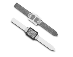
The DSG9500-000 is designed for low resistance, low capacitance and fast switching time. The oxide-nitride passivation layers provide reliable operation and stable junction parameters that provide complete sealing of the junction permitting use in assemblies with some degree of moisture sealing. The DSG9500-000 is ideal for microstrip or stripline circuits and for circuits requiring high isolation from a series mounted diode such as broad band multi-throw switches, phase shifters, limiters, attenuators and modulators.
Low Capacitance Planar Beam Lead Diode
Absolute Maximum Ratings
| Characteristic | Value |
| Operating temperature | -65 °C to +150 °C |
| Storage temperature | -65 °C to +200 °C |
| Power dissipation (derate linearly to zero @ 175 °C) | 250 mW |
| Typical lead strength | 8 grams pull |
Performance is guaranteed only under the conditions listed in the specifications table and is not guaranteed under the full range(s) described by the Absolute Maximum specifications. Exceeding any of the absolute maximum/minimum specifications may result in permanent damage to the device and will void the warranty.
CAUTION: Although this device is designed to be as robust as possible, Electrostatic Discharge (ESD) can damage this device. This device must be protected at all times from ESD. Static charges may easily produce potentials of several kilovolts on the human body or equipment, which can discharge without detection. Industry-standard ESD precautions must be employed at all times.
| Part Number | Breakdown Voltage @ 10 µA (V) | Capacitance Total @ 50 V, 1 MHz (pF) | Series Resistance (From Ins. Loss @ 3 GHz, 50 mA)(1) (Ω) | Minority Carrier Lifetime IF = 10 mA, IR = 6 mA (ns) | RF Switching Time TS (ns)(2) | Outline Drawing Number |
|---|---|---|---|---|---|---|
| Min. | Max. | Max. | Typ. | |||
| DSG9500–000 | 200 | 0.02 | 4.0 | 250 | 25 | 169-001 |
- Total capacitance calculated from isolation at 9 GHz zero bias. Series resistance and capacitance are measured at microwave frequencies on a sample basis from each lot. All diodes are characterized for capacitance at –50 V, 1 MHz, and series resistance at 1 KHz, 50 mA, measurements which correlate well with microwave measurements. 2. TS measured from RF transition, 90% to 10%, in series configuration.
Page 2
Performance Data for DSG9500–000
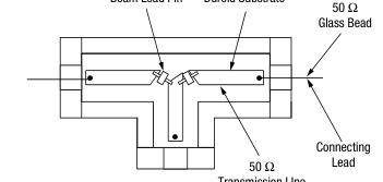
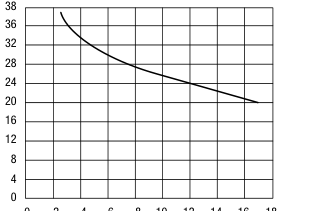
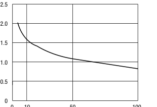
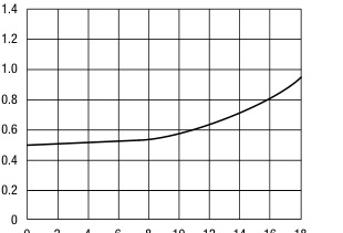
Figures 1 and 2 show a single pole double-throw 1–18 GHz switch these diodes are mounted an Alumina, Duroid, or Teflon fiberglass 50 Ω microstrip circuits. Typical bonding methods include thermal compression bonding, parallel gap welding, and soldering. SPDT isolation curves are shown in Figure 3 and insertion loss in Figures 4 and 5. With proper transitions and bias circuits, VSWR is better than 2.0 to 1 through 18 GHz.
Switching Considerations
The typical minority carrier lifetime of the DSG9500 diodes is 100 ns. With suitable drivers, the individual diodes can be switched from high impedance (off) to low RS (on) in about 10 ns.
Beam Lead Pin Duroid Substrate
Transmission LIne
Figure 1. Typical SPDT Circuit Arrangement
Preferred Beam
Beam Lead Pin
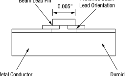
Figure 2. Typical Beam Lead Mounting
0 2 4 6 8 10 12 14 16 18
Frequency (GHz)
Figure 3. Isolation vs. Frequency, SPDT
0 10
50
100
Bias Current (mA) Figure 4. Diode Insertion Loss vs. Bias,
SPST 18 GHz
February 7, 2005 • Skyworks Proprietary Information • Products and Product Information are Subject to Change Without Notice. • 200137 Rev. A
Page 3
Power Handling for DSG9500–000
Beam lead diodes are not suitable for high power operation because of high internal thermal impedance of about 600 °C/W.
0 2 4 6 8 10 12 14 16 18
Frequency (GHz)
Figure 5. Diode Insertion Loss vs. Frequency,
SPST 50 mA Bias00
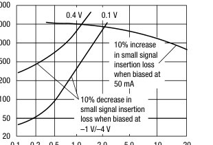
With maximum CW power dissipation of 250 mW, the DSG9500–000 diodes are normally rated at 2 W CW with linear derating between 25 °C and 150 °C. Figure 6 presents data on CW power handling as a function of bias and frequency.
5000
2000
1000
0.1 0.2 0.5 1.0 2.0
5.0 10 20
Frequency (GHz)
Figure 6. Typical Series Switch Behavior at Room Temperature and Biased at 50 mA/1 V/4 V
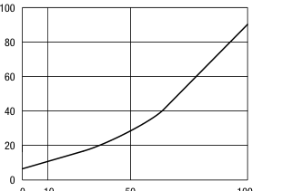
For pulsed operation, the total RF plus bias voltage must not exceed the rated breakdown. Skyworks has made high power tests at 1 GHz with 1 µs pulses, 0.001 duty, with 200 V diodes. With 50 mA forward bias, there is no increase in insertion loss over the 0 dBm level with a peak power input of 50 W. In the open state, reverse bias voltage is required to keep the diode from “rectifying,” with resultant decrease in isolation and possible failure. Figure 7 shows allowed peak power versus reverse bias at 1 GHz. At this frequency, the required reverse voltage is almost equal to the peak RF voltage; at high frequency, the bias can be reduced somewhat. Experimentation is necessary.
0 10
50
100
Reverse Bias (V) Figure 7. Peak Power Handling, SPST 1 GHz
169-001
0.004 (0.10 mm)
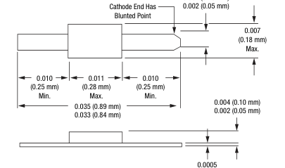
(0.013 mm) Max.
Page 4
Beam-Lead Diodes
Handling Due to their small size, beam-lead devices are fragile and should be handled with extreme care. The individual plastic packages should be handled and opened carefully, so that no undue mechanical strain is applied to the packaged device. It is recommended that the beam-lead devices be handled through use of a vacuum pencil using an appropriate size vacuum needle or a pointed wooden stick such as a sharpened Q-tip or match stick. The device will adhere to the point and can easily be removed from the container and positioned accurately for bonding without damage. Such handling should be done under a binocular microscope with magnification in the range of 20X to 30X.
Special handling precautions are also required to avoid electrical damage, such as static discharge.
Bonding The DSG9500-000 can best be bonded to substrates by means of thermocompression bonding. Essentially this type of bonding involves pressing the gold beam of the device against the gold plated metalized substrate under proper conditions of heat and pressure so that a metallurgical bond joint between the two occurs.
Procedure The beam-lead devices to be bonded should be placed on a clean, hard surface such as a microscope slide. It is recommended that the beam side of the device be down so that this side will be toward the substrate when bonded. The device can be picked up by pressing lightly against one beam with the heated tip. The substrate can then be appropriately positioned under the tip and the device brought down against the substrate, with proper pressure applied by means of the weld head. A bonding tip temperature in the 350 °C to 450 °C range is recommended along with a bonding force of 50 to 70 grams. The bonding time is in the range of 2 to 3 seconds. Optimum bonding
conditions should be determined by trial and error to compensate for slight variations in the condition of the substrate, bonding tip, and the type of device being bonded.
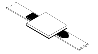
Equipment The heat and pressure are obtained through use of a silicon carbide bonding tip with a radius of two to three mils. Such an item is available from several commercial sources. In order to supply the required tip-travel and apply proper pressure, a standard miniature weld head can be used. Also available is a heated wedge shank which is held by the weld head and in turn holds the tip and supplies heat to it. The wedge shank is heated by means of a simple AC power supply or a pulse type heated tool.
Substrate For optimum bonding a gold plated surface at least 100 microinches thick is necessary. Although it is possible to bond to relatively soft metalized substrate material such as epoxy-fiberglass, etc., optimum bonding occurs when a hard material such as ceramic can be used.
Quality If a good bond has been obtained, it is impossible to separate the beam-lead device from the metalized substrate without damage. If the device is destructively removed, the beam will tear away, leaving the bonded portion attached to the substrate.
Beam–Lead Packaging
The DSG-9500-000 is shipped in 2" x 2" black gel packs. The beam-leads are mounted on the gel, the devices are covered with a piece of lint-free release paper, on top of which is placed a piece of conductive foam.
February 7, 2005 • Skyworks Proprietary Information • Products and Product Information are Subject to Change Without Notice. • 200137 Rev. A
Page 5
Copyright © 2002, 2003, 2004, 2005, Skyworks Solutions, Inc. All Rights Reserved.
Information in this document is provided in connection with Skyworks Solutions, Inc. (“Skyworks”) products. These materials are provided by Skyworks as a service to its customers and may be used for informational purposes only by the customer. Skyworks assumes no responsibility for errors or omissions in these materials. Skyworks may make changes to its documentation, products, specifications and product descriptions at any time, without notice. Skyworks makes no commitment to update the information and shall have no responsibility whatsoever for conflicts, incompatibilities, or other difficulties arising from future changes to its documentation, products, specifications and product descriptions.
No license, express or implied, by estoppel or otherwise, to any intellectual property rights is granted by or under this document. Except as may be provided in Skyworks Terms and Conditions of Sale for such products, Skyworks assumes no liability whatsoever in association with its documentation, products, specifications and product descriptions.
THESE MATERIALS ARE PROVIDED “AS IS” WITHOUT WARRANTY OF ANY KIND, EITHER EXPRESS OR IMPLIED OR OTHERWISE, RELATING TO SALE AND/OR USE OF SKYWORKS PRODUCTS INCLUDING WARRANTIES RELATING TO FITNESS FOR A PARTICULAR PURPOSE, MERCHANTABILITY, PERFORMANCE, QUALITY OR NON-INFRINGEMENT OF ANY PATENT, COPYRIGHT OR OTHER INTELLECTUAL PROPERTY RIGHT. SKYWORKS FURTHER DOES NOT WARRANT THE ACCURACY OR COMPLETENESS OF THE INFORMATION, TEXT, GRAPHICS OR OTHER ITEMS CONTAINED WITHIN THESE MATERIALS. SKYWORKS SHALL NOT BE LIABLE FOR ANY DAMAGES, INCLUDING SPECIAL, INDIRECT, INCIDENTAL, OR CONSEQUENTIAL DAMAGES, INCLUDING WITHOUT LIMITATION, LOST REVENUES OR LOST
PROFITS THAT MAY RESULT FROM THE USE OF THESE MATERIALS WHETHER OR NOT THE RECIPIENT OF MATERIALS HAS BEEN ADVISED OF THE POSSIBILITY OF SUCH DAMAGE.
Skyworks products are not intended for use in medical, lifesaving or life-sustaining applications. Skyworks customers using or selling Skyworks products for use in such applications do so at their own risk and agree to fully indemnify Skyworks for any damages resulting from such improper use or sale.
The following are trademarks of Skyworks Solutions, Inc.: Skyworks®, the Skyworks logo, and Breakthrough Simplicity®. Product names or services listed in this publication are for identification purposes only, and may be trademarks of Skyworks or other third parties. Third-party brands and names are the property of their respective owners. Additional information, posted at www.skyworksinc.com, is incorporated by reference.