
 Download PDF
DSEA59-06BC IXYS
Document overview
- PDF pages: 2
Technical content
Page 1
HiPerFREDTM Epitaxial Diode
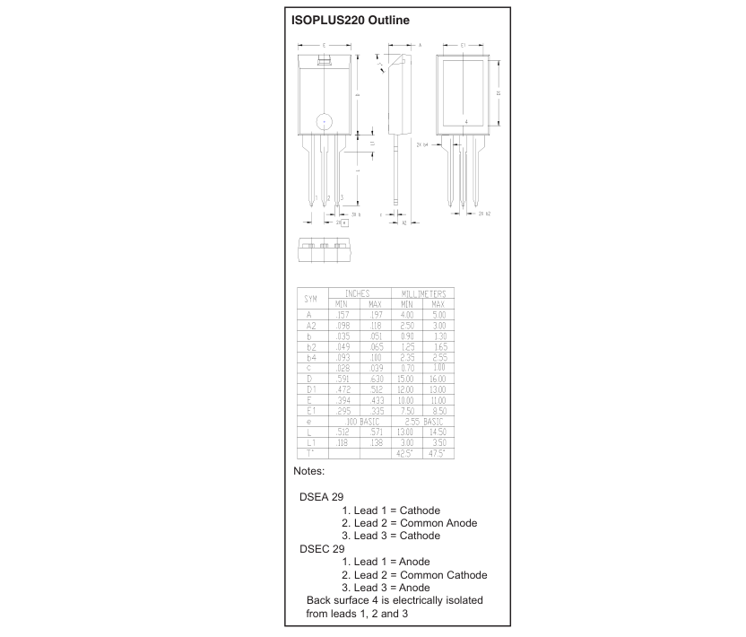
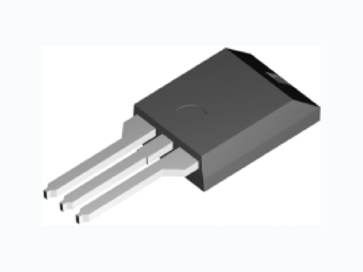
ISOPLUS220TM
Electrically Isolated Back Surface
DSEA
Preliminary Data Sheet
VRSM
VRRM
Type
1
V V
DSEC
600 600
DSEA 59-06BC DSEC 59-06BC
1
Symbol
Conditions
Lead current limit
IFRMSc
IFAVM
TC = 105°C; rectangular, d = 0.5
IFSM
TVJ = 45°C; tp = 10 ms (50 Hz), sine
EAS
TVJ = 25°C; non-repetitive IAS = 1.3 A; L = 180 µH
IAR
VA = 1.5·VR typical; f = 10 kHz; repetitive
TVJ
TVJM
Tstg TL
1.6 mm (0.063 in) from case for 10 s
Ptot
TC = 25°C
VISOL
50/60 Hz RMS; IISOL ≤ 1 mA
FC
Mounting force
Weight
typical
Symbol
Conditions
DSEA 59-06BC DSEC 59-06BC
IFAV
= 2x30 A
VRRM = 600 V
trr = 35 ns
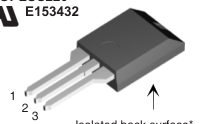
ISOPLUS220TM
2 3
2 3
Isolated back surface\*
Maximum Ratings
Features
45
A z Silicon chip on Direct-Copper-Bond
30
A substrate
200
A - High power dissipation
0.2
mJ - Isolated mounting surface - 2500V electrical isolation z Low cathode to tab capacitance (<15pF)
0.1
A z Planar passivated chips
-40...+175
°C z Very short recovery time
175
°C z Extremely low switching losses
-40...+150
°C z Low IRM-values z Soft recovery behaviour °C
260
z Epoxy meets UL 94V-0
136
W
2500
V~
Applications
11...65 / 2.5...15 N / lb
z Antiparallel diode for high frequency
2
g switching devices z Antisaturation diode
Characteristic Values
z Snubber diode z Free wheeling diode in converters
| typ. | max. |
|---|---|
| I d T = 25°C V = V R VJ R RRM T = 150°C V = V VJ R RRM | 250 µA 2 mA |
| V e I = 30 A; T = 150°C F F VJ T = 25°C VJ | 1.56 V 2.51 V |
| R thJC R 0.6 thCH | 1.1 K/W K/W |
| t I = 1 A; -di/dt = 200 A/µs; 30 rr F V = 30 V; T = 25°C R VJ | ns |
| I V = 100 V; I = 50 A; -di /dt = 100 A/µs 4 RM R F F T = 100°C VJ | A |
and motor control circuits z Rectifiers in switch mode power supplies (SMPS) z Inductive heating z Uninterruptible power supplies (UPS) z Ultrasonic cleaners and welders
Advantages z Avalanche voltage rated for reliable operation z Soft reverse recovery for low EMI/RFI z Low IRM reduces: - Power dissipation within the diode - Turn-on loss in the commutating switch
Notes: Data given for TVJ = 25OC and per diode unless otherwise specified c Average current per diode may be limited by center lead RMS current limit when
See DSEP 29-06B data sheet for
both diodes are conducting.
characteristic curves
d Pulse test: pulse Width = 5 ms, Duty Cycle < 2.0 % e Pulse test: pulse Width = 300 µs, Duty Cycle < 2.0 %
IXYS reserves the right to change limits, test conditions and dimensions.
DS98817A(07/03)
© 2003 IXYS All rights reserved
Page 2
DSEA 59-06BC DSEC 59-06BC