

 Download PDF
DS90 BRIDGELUX
Document overview
- PDF pages: 37
Technical content
Page 1
Page 2
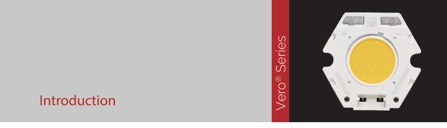
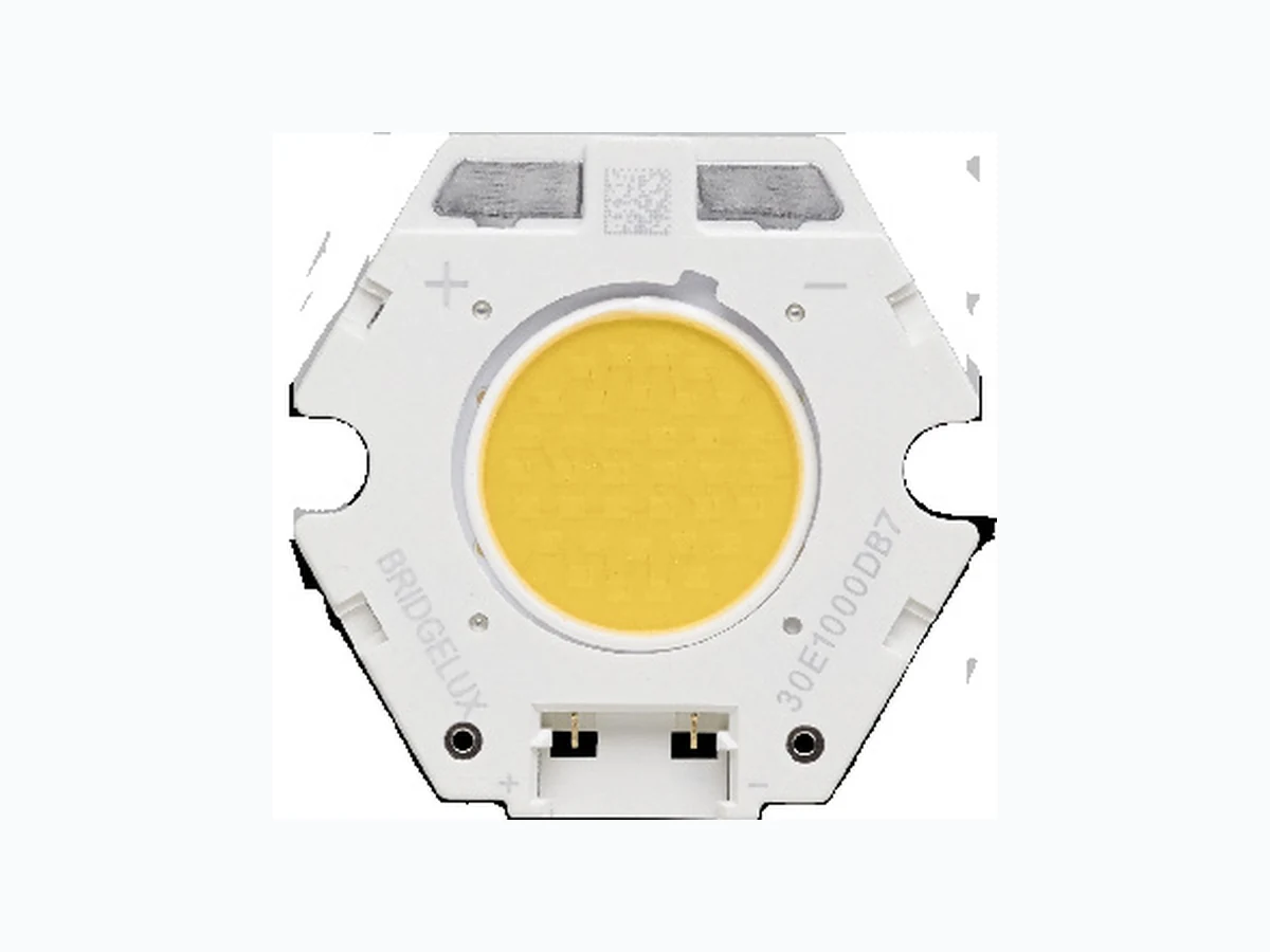
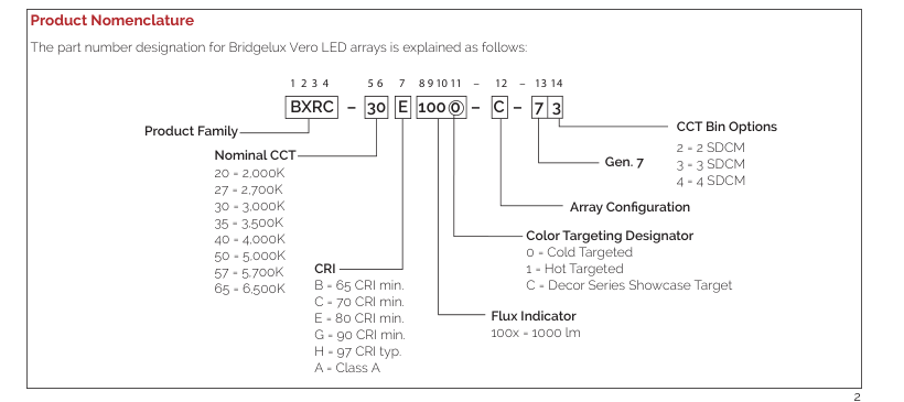
Vero® Series is a revolutionary advancement in chip on board (COB) light source technology and innovation. Vero LED light sources simplify luminaire design and manufacturing processes Vero Chip on Board (COB) LED arrays are available in four LES configurations, engineered to enable new degrees of flexibility and reliability over a broad range of electrical currents. Vero arrays deliver increased lumen density to enable improved beam control and precision lighting with 2 and 3 SDCM color control standard for clean and consistent uniform lighting.
Vero products include an onboard connector port that enables a solder-free electrical interconnect, and simple mounting features for plug-and-play installation.
Bridgelux Décor Series™ is our state-of-the-art color line designed specifically for premium applications, producing unmatched LED light quality with brilliant color-rendering options and pleasing lighting palettes. Bridgelux Décor Series color points are available on Vero® SE Series, Vero® Series, V Series™ and V Series™ HD.
Décor Series™ Class A is based on human response testing, providing color points with a combined GAI and CRI metric.
Décor Series™ Ultra products provide a high CRI of 97 and minimum R9 value of 93, which emphasizes the reds and color tones to which the human eye is most receptive - perfect for the most luxurious retail shops and world renowned museums. Décor Series Ultra is designed as a replacement for halogen lamps.
Décor Series™ Street and Landmark is designed to be a direct replacement for high pressure sodium lamps.
Décor Series™ Showcase is the optimal solution for replacing ceramic metal halide lamps, incorporating the same pure white light with enhanced spectrum coverage and higher efficacy.
Features
- Efficacy of 167 lm/W typical
- Lumen output performance ranges from 520 to 4,100 lumens
- Broad range of CCT options from 2700K to 6500K
- CRI options include minimum 65, 70, 80, and 90
- 2 and 3 SDCM color control for 2700K-4000K CCT
- Reliable operation at up to 2X nominal drive current
- Radial die pattern and improved lumen density
- Thermally isolated solder pads
- On-board connector port
- Top side part number markings
- Vf bin code backside marking
Benefits
- Broad application coverage for interior and exterior lighting
- Flexibility for application driven lighting design requirements
- High quality true color reproduction
- Uniform consistent white light
- Flexibility in design optimization
- Enhanced ease of use and assembly
- Solderless connectivity enables plug & play installation and field upgradability
- Improved inventory management and quality control
Page 3

Page 4

Vero 10 is the smallest form factor in the Vero family of next generation solid state light sources. In addition to delivering the performance and light quality required for many lighting applications, Vero incorporates several
2D Bar code provides full manufacturing traceability
features to simplify the design integration and manufacturing process, accelerate time to market and reduce system costs. Please visit www.bridgelux.com for more information on the Vero Series family of products.
Thermally isolated solder pads reduce
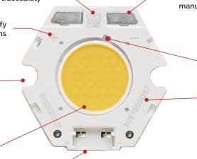
Polarity indication marks simplify manufacturing operator instructions
Mounting holes
Radial die configuration improves lumen density and beam control
Solderless connector port enables simplified manufacturing processes, reduced inventory carrying costs and can enable field upgradability
manufacturing cycle time and complexity
Tc Measurement point
Top side part number marking improves inventory management and outgoing quality control
Optional Bridgelux Vero wire harness (sold separately)
Page 5

The following product configurations are available:
Table 1: Selection Guide, Pulsed Measurement Data (Tj = Tc = 25°C)
| Part Number | Nominal CCT1 (K) | CRI2 | Nominal Drive Current3 (mA) | Typical Pulsed Flux4,5,6 T = 25ºC c (lm) | Minimum Pulsed Flux6,7 T = 25ºC c (lm) | Typical V f (V) | Typical Power (W) | Typical Efficacy (lm/W) |
|---|---|---|---|---|---|---|---|---|
| BXRC-20B1000-B-7x | 2000 | 65 | 270 | 1431 | 1259 | 34.8 | 9.4 | 152 |
| BXRC-20B1000-D-7x | 2000 | 65 | 350 | 1386 | 1220 | 26.0 | 9.1 | 152 |
| BXRC-27E1000-B-7x | 2700 | 80 | 270 | 1458 | 1283 | 34.8 | 9.4 | 155 |
| BXRC-27E1000-C-7x | 2700 | 80 | 360 | 1944 | 1711 | 34.8 | 12.5 | 155 |
| BXRC-27E1000-D-7x | 2700 | 80 | 350 | 1412 | 1243 | 26.0 | 9.1 | 155 |
| BXRC-27G10H0-B-7x | 2700 | 90 | 270 | 1249 | 1099 | 34.8 | 9.4 | 133 |
| BXRC-27G10H0-C-7x | 2700 | 90 | 360 | 1665 | 1465 | 34.8 | 12.5 | 133 |
| BXRC-27G10H0-D-7x | 2700 | 90 | 350 | 1209 | 1064 | 26.0 | 9.1 | 133 |
| BXRC-27G1000-B-7x | 2700 | 90 | 270 | 1203 | 1059 | 34.8 | 9.4 | 128 |
| BXRC-27G1000-C-7x | 2700 | 90 | 360 | 1604 | 1412 | 34.8 | 12.5 | 128 |
| BXRC-27G1000-D-7x | 2700 | 90 | 350 | 1165 | 1025 | 26.0 | 9.1 | 128 |
| BXRC-27H1000-B-7x | 2700 | 97 | 270 | 1066 | 938 | 34.8 | 9.4 | 113 |
| BXRC-27H1000-C-7x | 2700 | 97 | 360 | 1422 | 1251 | 34.8 | 12.5 | 113 |
| BXRC-27H1000-D-7x | 2700 | 97 | 350 | 1033 | 909 | 26.0 | 9.1 | 113 |
| BXRC-30C1001-B-7x | 3000 | 70 | 270 | 1622 | 1428 | 34.8 | 9.4 | 173 |
| BXRC-30C1001-C-7x | 3000 | 70 | 360 | 2163 | 1904 | 34.8 | 12.5 | 173 |
| BXRC-30C1001-D-7x | 3000 | 70 | 350 | 1571 | 1383 | 26.0 | 9.1 | 173 |
| BXRC-30E1000-B-7x | 3000 | 80 | 270 | 1549 | 1363 | 34.8 | 9.4 | 165 |
| BXRC-30E1000-C-7x | 3000 | 80 | 360 | 2066 | 1818 | 34.8 | 12.5 | 165 |
| BXRC-30E1000-D-7x | 3000 | 80 | 350 | 1501 | 1321 | 26.0 | 9.1 | 165 |
| BXRC-30G10H0-B-7x | 3000 | 90 | 270 | 1312 | 1155 | 34.8 | 9.4 | 140 |
| BXRC-30G10H0-C-7x | 3000 | 90 | 360 | 1750 | 1540 | 34.8 | 12.5 | 140 |
| BXRC-30G10H0-D-7x | 3000 | 90 | 350 | 1271 | 1119 | 26.0 | 9.1 | 140 |
| BXRC-30G1000-B-7x | 3000 | 90 | 270 | 1258 | 1107 | 34.8 | 9.4 | 134 |
| BXRC-30G1000-C-7x | 3000 | 90 | 360 | 1677 | 1476 | 34.8 | 12.5 | 134 |
| BXRC-30G1000-D-7x | 3000 | 90 | 350 | 1218 | 1072 | 26.0 | 9.1 | 134 |
| BXRC-30G100C-B-7x | 3000 | 90 | 270 | 1212 | 1067 | 34.8 | 9.4 | 129 |
| BXRC-30G100C-D-7x | 3000 | 90 | 350 | 1174 | 1033 | 26.0 | 9.1 | 129 |
| BXRC-30H1000-B-7x | 3000 | 97 | 270 | 1139 | 1003 | 34.8 | 9.4 | 121 |
| BXRC-30H1000-C-7x | 3000 | 97 | 360 | 1519 | 1337 | 34.8 | 12.5 | 121 |
| BXRC-30H1000-D-7x | 3000 | 97 | 350 | 1103 | 971 | 26.0 | 9.1 | 121 |
| BXRC-30A1001-B-7x8,9 | 3000 | 93 | 270 | 1130 | 995 | 34.8 | 9.4 | 120 |
Notes for Table 1: 1. Nominal CCT as defined by ANSI C78.377-2011. Products with a CCT of 5000K-6500K are hot targeted to Tc = 85°C. 2. CRI values are typical for Decor Series Ultra, Decor Series Street and Landmark and Decor Series Class A products. CRI values are minimums for all other products. Minimum R9 value for 80 CRI products is 0, the minimum R9 value for 90 CRI products is 50, the minimum R9 value for 97 CRI products is 93 when 2700K and 3000K. Bridgelux maintains a ± 3 tolerance on CRI and R9 values. 3. Drive current is referred to as nominal drive current. 4. Products tested under pulsed condition (10ms pulse width) at nominal test current where Tj (junction temperature) = Tc (case temperature) = 25°C.
- Typical performance values are provided as a reference only and are not a guarantee of performance. 6. Bridgelux maintains a ±7% tolerance on flux measurements. 7. Minimum flux values at the nominal test current are guaranteed by 100% test. 8. Nominal CCT is defined by the Lighting Research Center’s Class A definition. The center of the Class A color bin is on the corresponding isothermal line. 9. GAI value is 80. To help ensure optimal fixture level performance, GAI is measured at the fixture level, on axis, at a case temperature of 70°C. GAI may vary depending on fixture design and performance.
Page 6

Table 1: Selection Guide, Pulsed Measurement Data (Tj = Tc = 25°C) (continued)
| Part Number | Nominal CCT1 (K) | CRI2 | Nominal Drive Current3 (mA) | Typical Pulsed Flux4,5,6 T = 25ºC c (lm) | Minimum Pulsed Flux6,7 T = 25ºC c (lm) | Typical V f (V) | Typical Power (W) | Typical Efficacy (lm/W) |
|---|---|---|---|---|---|---|---|---|
| BXRC-30A1001-C-7x8,9 | 3000 | 93 | 360 | 1507 | 1326 | 34.8 | 12.5 | 120 |
| BXRC-30A1001-D-7x8,9 | 3000 | 93 | 350 | 1095 | 963 | 26.0 | 9.1 | 120 |
| BXRC-35E1000-B-7x | 3500 | 80 | 270 | 1586 | 1396 | 34.8 | 9.4 | 169 |
| BXRC-35E1000-C-7x | 3500 | 80 | 360 | 2114 | 1861 | 34.8 | 12.5 | 169 |
| BXRC-35E1000-D-7x | 3500 | 80 | 350 | 1536 | 1352 | 26.0 | 9.1 | 169 |
| BXRC-35G1000-B-7x | 3500 | 90 | 270 | 1303 | 1147 | 34.8 | 9.4 | 139 |
| BXRC-35G1000-C-7x | 3500 | 90 | 360 | 1738 | 1529 | 34.8 | 12.5 | 139 |
| BXRC-35G1000-D-7x | 3500 | 90 | 350 | 1262 | 1111 | 26.0 | 9.1 | 139 |
| BXRC-35A1001-B-7x8,9 | 3500 | 93 | 270 | 1203 | 1059 | 34.8 | 9.4 | 128 |
| BXRC-35A1001-C-7x8,9 | 3500 | 93 | 360 | 1604 | 1412 | 34.8 | 12.5 | 128 |
| BXRC-35A1001-D-7x8,9 | 3500 | 93 | 350 | 1165 | 1025 | 26.0 | 9.1 | 128 |
| BXRC-40C1001-B-7x | 4000 | 70 | 270 | 1668 | 1468 | 34.8 | 9.4 | 178 |
| BXRC-40C1001-C-7x | 4000 | 70 | 360 | 2224 | 1957 | 34.8 | 12.5 | 178 |
| BXRC-40C1001-D-7x | 4000 | 70 | 350 | 1615 | 1422 | 26.0 | 9.1 | 178 |
| BXRC-40E1000-B-7x | 4000 | 80 | 270 | 1595 | 1404 | 34.8 | 9.4 | 170 |
| BXRC-40E1000-C-7x | 4000 | 80 | 360 | 2127 | 1871 | 34.8 | 12.5 | 170 |
| BXRC-40E1000-D-7x | 4000 | 80 | 350 | 1545 | 1359 | 26.0 | 9.1 | 170 |
| BXRC-40G1000-B-7x | 4000 | 90 | 270 | 1331 | 1171 | 34.8 | 9.4 | 142 |
| BXRC-40G1000-C-7x | 4000 | 90 | 360 | 1774 | 1561 | 34.8 | 12.5 | 142 |
| BXRC-40G1000-D-7x | 4000 | 90 | 350 | 1289 | 1134 | 26.0 | 9.1 | 142 |
| BXRC-40H1000-B-7x | 4000 | 97 | 270 | 1203 | 1059 | 34.8 | 9.4 | 128 |
| BXRC-40H1000-C-7x | 4000 | 97 | 360 | 1604 | 1412 | 34.8 | 12.5 | 128 |
| BXRC-40H1000-D-7x | 4000 | 97 | 350 | 1165 | 1025 | 26.0 | 9.1 | 128 |
| BXRC-40A1001-B-7x8,9 | 4000 | 93 | 270 | 1303 | 1147 | 34.8 | 9.4 | 139 |
| BXRC-40A1001-C-7x8,9 | 4000 | 93 | 360 | 1738 | 1529 | 34.8 | 12.5 | 139 |
| BXRC-40A1001-D-7x8,9 | 4000 | 93 | 350 | 1262 | 1111 | 26.0 | 9.1 | 139 |
| BXRC-50C1001-B-7x | 5000 | 70 | 270 | 1677 | 1476 | 34.8 | 9.4 | 178 |
| BXRC-50C1001-C-7x | 5000 | 70 | 360 | 2236 | 1968 | 34.8 | 12.5 | 178 |
| BXRC-50C1001-D-7x | 5000 | 70 | 350 | 1624 | 1429 | 26.0 | 9.1 | 178 |
| BXRC-50E1001-B-7x | 5000 | 80 | 270 | 1613 | 1420 | 34.8 | 9.4 | 172 |
| BXRC-50E1001-C-7x | 5000 | 80 | 360 | 2151 | 1893 | 34.8 | 12.5 | 172 |
| BXRC-50E1001-D-7x | 5000 | 80 | 350 | 1562 | 1375 | 26.0 | 9.1 | 172 |
| BXRC-50G1001-B-7x | 5000 | 90 | 270 | 1394 | 1227 | 34.8 | 9.4 | 148 |
| BXRC-50G1001-C-7x | 5000 | 90 | 360 | 1859 | 1636 | 34.8 | 12.5 | 148 |
| BXRC-50G1001-D-7x | 5000 | 90 | 350 | 1351 | 1188 | 26.0 | 9.1 | 148 |
Notes for Table 1: 1. Nominal CCT as defined by ANSI C78.377-2011. Products with a CCT of 5000K-6500K are hot targeted to Tc = 85°C. 2. CRI values are typical for Decor Series Ultra, Decor Series Street and Landmark and Decor Series Class A products. CRI values are minimums for all other products. Minimum R9 value for 80 CRI products is 0, the minimum R9 value for 90 CRI products is 50, the minimum R9 value for 97 CRI products is 93 when 2700K and 3000K. Bridgelux maintains a ± 3 tolerance on CRI and R9 values. 3. Drive current is referred to as nominal drive current. 4. Products tested under pulsed condition (10ms pulse width) at nominal test current where Tj (junction temperature) = Tc (case temperature) = 25°C.
- Typical performance values are provided as a reference only and are not a guarantee of performance. 6. Bridgelux maintains a ±7% tolerance on flux measurements. 7. Minimum flux values at the nominal test current are guaranteed by 100% test. 8. Nominal CCT is defined by the Lighting Research Center’s Class A definition. The center of the Class A color bin is on the corresponding isothermal line. 9. GAI value is 80. To help ensure optimal fixture level performance, GAI is measured at the fixture level, on axis, at a case temperature of 70°C. GAI may vary depending on fixture design and performance.
Page 7

Table 1: Selection Guide, Pulsed Measurement Data (Tj = Tc = 25°C) (continued)
| Part Number | Nominal CCT1 (K) | CRI2 | Nominal Drive Current3 (mA) | Typical Pulsed Flux4,5,6 T = 25ºC c (lm) | Minimum Pulsed Flux6,7 T = 25ºC c (lm) | Typical V f (V) | Typical Power (W) | Typical Efficacy (lm/W) |
|---|---|---|---|---|---|---|---|---|
| BXRC-57C1001-B-7x | 5700 | 70 | 270 | 1631 | 1436 | 34.8 | 9.4 | 174 |
| BXRC-57C1001-C-7x | 5700 | 70 | 360 | 2175 | 1914 | 34.8 | 12.5 | 174 |
| BXRC-57C1001-D-7x | 5700 | 70 | 350 | 1580 | 1390 | 26.0 | 9.1 | 174 |
| BXRC-57E1001-B-7x | 5700 | 80 | 270 | 1549 | 1363 | 34.8 | 9.4 | 165 |
| BXRC-57E1001-C-7x | 5700 | 80 | 360 | 2066 | 1818 | 34.8 | 12.5 | 165 |
| BXRC-57E1001-D-7x | 5700 | 80 | 350 | 1501 | 1321 | 26.0 | 9.1 | 165 |
| BXRC-65C1001-B-7x | 6500 | 70 | 270 | 1631 | 1436 | 34.8 | 9.4 | 174 |
| BXRC-65C1001-C-7x | 6500 | 70 | 360 | 2175 | 1914 | 34.8 | 12.5 | 174 |
| BXRC-65C1001-D-7x | 6500 | 70 | 350 | 1580 | 1390 | 26.0 | 9.1 | 174 |
| BXRC-65E1001-B-7x | 6500 | 80 | 270 | 1568 | 1380 | 34.8 | 9.4 | 167 |
| BXRC-65E1001-C-7x | 6500 | 80 | 360 | 2090 | 1839 | 34.8 | 12.5 | 167 |
| BXRC-65E1001-D-7x | 6500 | 80 | 350 | 1518 | 1336 | 26.0 | 9.1 | 167 |
Notes for Table 1: 1. Nominal CCT as defined by ANSI C78.377-2011. Products with a CCT of 5000K-6500K are hot targeted to Tc = 85°C. 2. CRI values are typical for Decor Series Ultra, Decor Series Street and Landmark and Decor Series Class A products. CRI values are minimums for all other products. Minimum R9 value for 80 CRI products is 0, the minimum R9 value for 90 CRI products is 50, the minimum R9 value for 97 CRI products is 93 when 2700K and 3000K. Bridgelux maintains a ± 3 tolerance on CRI and R9 values. 3. Drive current is referred to as nominal drive current. 4. Products tested under pulsed condition (10ms pulse width) at nominal test current where Tj (junction temperature) = Tc (case temperature) = 25°C.
- Typical performance values are provided as a reference only and are not a guarantee of performance. 6. Bridgelux maintains a ±7% tolerance on flux measurements. 7. Minimum flux values at the nominal test current are guaranteed by 100% test. 8. Nominal CCT is defined by the Lighting Research Center’s Class A definition. The center of the Class A color bin is on the corresponding isothermal line. 9. GAI value is 80. To help ensure optimal fixture level performance, GAI is measured at the fixture level, on axis, at a case temperature of 70°C. GAI may vary depending on fixture design and performance.
Page 8

Table 2: Selection Guide, Stabilized DC Performance (Tc = 70°C) 7,8
| Part Number | Nominal CCT1 (K) | GAI2 | CRI3 | Nominal Drive Current4 (mA) | Typical DC Flux5,6 T = 70ºC c (lm) | Minimum DC Flux6,9 T = 70ºC c (lm) | Typical V f (V) | Typical Power (W) | Typical Efficacy (lm/W) |
|---|---|---|---|---|---|---|---|---|---|
| BXRC-30A1001-B-7x | 3000 | 80 | 93 | 270 | 1051 | 875 | 34.3 | 9.3 | 114 |
| BXRC-30A1001-C-7x | 3000 | 80 | 93 | 360 | 1401 | 1167 | 34.3 | 12.3 | 114 |
| BXRC-30A1001-D-7x | 3000 | 80 | 93 | 350 | 1018 | 848 | 25.5 | 8.9 | 114 |
| BXRC-35A1001-B-7x | 3500 | 80 | 93 | 270 | 1119 | 1228 | 34.3 | 9.3 | 121 |
| BXRC-35A1001-C-7x | 3500 | 80 | 93 | 360 | 1492 | 1637 | 34.3 | 12.3 | 121 |
| BXRC-35A1001-D-7x | 3500 | 80 | 93 | 350 | 1084 | 1189 | 25.5 | 8.9 | 122 |
| BXRC-40A1001-B-7x | 4000 | 80 | 93 | 270 | 1212 | 1009 | 34.3 | 9.3 | 131 |
| BXRC-40A1001-C-7x | 4000 | 80 | 93 | 360 | 1616 | 1346 | 34.3 | 12.3 | 131 |
| BXRC-40A1001-D-7x | 4000 | 80 | 93 | 350 | 1174 | 977 | 25.5 | 8.9 | 132 |
Notes for Table 2: 1. Nominal CCT is defined by the Lighting Research Center’s Class A definition. The center of the Class A color bin is on the corresponding isothermal line. 2. To help ensure optimal fixture level performance, GAI is measured at the fixture level, on axis, at a case temperature of 70°C. GAI may vary depending on fixture design and performance. 3. CRI Values are specified as typical. 4. Drive current is referred to as nominal drive current. 5. Typical performance values are provided as a reference only and are not a guarantee of performance. 6. Bridgelux maintains a ±7% tolerance on flux measurements. 7. Typical stabilized DC performance values are provided as reference only and are not a guarantee of performance.
- Typical performance is estimated based on operation under DC (direct current) with LED array mounted onto a heat sink with thermal interface material and the case temperature maintained at specified temperature. Based on Bridgelux test setup, values may vary depending on the thermal design of the luminaire and/or the exposed environment to which the product is subjected. 9. Minimum flux values at elevated temperatures are provided for reference only and are not guaranteed by 100% production testing. Based on Bridgelux test setup, values may vary depending on the thermal design of the luminaire and/or the exposed environment to which the product is subjected.
Page 9

Table 3: Selection Guide, Stabilized DC Performance (Tc = 85°C) 4,5
| Part Number | Nominal CCT1 (K) | CRI2 | Nominal Drive Current3 (mA) | Typical DC Flux4,5 T = 85ºC c(lm) | Minimum DC Flux6 T = 85ºC c(lm) | Typical V (V) f | Typical Power (W) | Typical Efficacy (lm/W) |
|---|---|---|---|---|---|---|---|---|
| BXRC-20B1000-B-7x | 2000 | 65 | 270 | 1288 | 1133 | 33.8 | 9.1 | 141 |
| BXRC-20B1000-D-7x | 2000 | 65 | 350 | 1247 | 1098 | 25.3 | 8.9 | 141 |
| BXRC-27E1000-B-7x | 2700 | 80 | 270 | 1312 | 1155 | 33.8 | 9.1 | 144 |
| BXRC-27E1000-C-7x | 2700 | 80 | 360 | 1750 | 1540 | 33.8 | 12.2 | 144 |
| BXRC-27E1000-D-7x | 2700 | 80 | 350 | 1271 | 1119 | 25.3 | 8.9 | 144 |
| BXRC-27G10H0-B-7x | 2700 | 90 | 270 | 1124 | 989 | 33.8 | 9.1 | 123 |
| BXRC-27G10H0-C-7x | 2700 | 90 | 360 | 1498 | 1319 | 33.8 | 12.2 | 123 |
| BXRC-27G10H0-D-7x | 2700 | 90 | 350 | 1088 | 958 | 25.3 | 8.9 | 123 |
| BXRC-27G1000-B-7x | 2700 | 90 | 270 | 1083 | 953 | 33.8 | 9.1 | 119 |
| BXRC-27G1000-C-7x | 2700 | 90 | 360 | 1444 | 1270 | 33.8 | 12.2 | 119 |
| BXRC-27G1000-D-7x | 2700 | 90 | 350 | 1049 | 923 | 25.3 | 8.9 | 118 |
| BXRC-27H1000-B-7x | 2700 | 97 | 270 | 960 | 845 | 33.8 | 9.1 | 105 |
| BXRC-27H1000-C-7x | 2700 | 97 | 360 | 1280 | 1126 | 33.8 | 12.2 | 105 |
| BXRC-27H1000-D-7x | 2700 | 97 | 350 | 929 | 818 | 25.3 | 8.9 | 105 |
| BXRC-30C1001-B-7x | 3000 | 70 | 270 | 1460 | 1285 | 33.8 | 9.1 | 160 |
| BXRC-30C1001-C-7x | 3000 | 70 | 360 | 1947 | 1713 | 33.8 | 12.2 | 160 |
| BXRC-30C1001-D-7x | 3000 | 70 | 350 | 1414 | 1244 | 25.3 | 8.9 | 160 |
| BXRC-30E1000-B-7x | 3000 | 80 | 270 | 1394 | 1227 | 33.8 | 9.1 | 153 |
| BXRC-30E1000-C-7x | 3000 | 80 | 360 | 1859 | 1636 | 33.8 | 12.2 | 153 |
| BXRC-30E1000-D-7x | 3000 | 80 | 350 | 1351 | 1188 | 25.3 | 8.9 | 153 |
| BXRC-30G10H0-B-7x | 3000 | 90 | 270 | 1181 | 1039 | 33.8 | 9.1 | 129 |
| BXRC-30G10H0-C-7x | 3000 | 90 | 360 | 1575 | 1386 | 33.8 | 12.2 | 129 |
| BXRC-30G10H0-D-7x | 3000 | 90 | 350 | 1144 | 1007 | 25.3 | 8.9 | 129 |
| BXRC-30G1000-B-7x | 3000 | 90 | 270 | 1132 | 996 | 33.8 | 9.1 | 124 |
| BXRC-30G1000-C-7x | 3000 | 90 | 360 | 1509 | 1328 | 33.8 | 12.2 | 124 |
| BXRC-30G1000-D-7x | 3000 | 90 | 350 | 1096 | 965 | 25.3 | 8.9 | 124 |
| BXRC-30G100C-B-7x | 3000 | 90 | 270 | 1091 | 960 | 33.8 | 9.1 | 120 |
| BXRC-30G100C-D-7x | 3000 | 90 | 350 | 1057 | 930 | 25.3 | 8.9 | 119 |
| BXRC-30H1000-B-7x | 3000 | 97 | 270 | 1025 | 902 | 33.8 | 9.1 | 112 |
| BXRC-30H1000-C-7x | 3000 | 97 | 360 | 1367 | 1203 | 33.8 | 12.2 | 112 |
| BXRC-30H1000-D-7x | 3000 | 97 | 350 | 993 | 874 | 25.3 | 8.9 | 112 |
| BXRC-30A1001-B-7x7,8 | 3000 | 93 | 270 | 1017 | 895 | 33.8 | 9.1 | 111 |
| BXRC-30A1001-C-7x7,8 | 3000 | 93 | 360 | 1356 | 1193 | 33.8 | 12.2 | 111 |
| BXRC-30A1001-D-7x7,8 | 3000 | 93 | 350 | 985 | 867 | 25.3 | 8.9 | 111 |
| BXRC-35E1000-B-7x | 3500 | 80 | 270 | 1427 | 1256 | 33.8 | 9.1 | 156 |
Notes for Table 3: 1. Nominal CCT as defined by ANSI C78.377-2011. Products with a CCT of 5000K-6500K are hot targeted to Tc = 85°C. 2. All CRI values are measured at Tj = Tc = 25°C. CRI values are typical for Decor Series Ultra, Decor Series Street and Landmark and Decor Series Class A products. CRI values are minimums for all other products. Minimum R9 value for 80 CRI products is 0, the minimum R9 value for 90 CRI products is 50, the minimum R9 value for 97 CRI products is 93 when 2700K and 3000K. Bridgelux maintains a ± 3 tolerance on CRI and R9 values. 3. Drive current is referred to as nominal drive current. 4. Typical stabilized DC performance values are provided as reference only and are not a guarantee of performance.
- Typical performance is estimated based on operation under DC (direct current) with LED array mounted onto a heat sink with thermal interface material and the case temperature maintained at 85°C. Based on Bridgelux test setup, values may vary depending on the thermal design of the luminaire and/or the exposed environment to which the product is subjected. 6. Minimum flux values at elevated temperatures are provided for reference only and are not guaranteed by 100% production testing. Based on Bridgelux test setup, values may vary depending on the thermal design of the luminaire and/or the exposed environment to which the product is subjected. 7. Nominal CCT is defined by the Lighting Research Center’s Class A definition. The center of the Class A color bin is on the corresponding isothermal line.
- GAI value is 80. To help ensure optimal fixture level performance, GAI is measured at the fixture level, on axis, at a case temperature of 70°C. GAI may vary depending on fixture design and performance.
Page 10

Table 3: Selection Guide, Stabilized DC Performance (Tc = 85°C) 4,5 (continued)
| Part Number | Nominal CCT1 (K) | CRI2 | Nominal Drive Current3 (mA) | Typical DC Flux4,5 T = 85ºC c(lm) | Minimum DC Flux6 T = 85ºC c(lm) | Typical V (V) f | Typical Power (W) | Typical Efficacy (lm/W) |
|---|---|---|---|---|---|---|---|---|
| BXRC-35E1000-C-7x | 3500 | 80 | 360 | 1903 | 1675 | 33.8 | 12.2 | 156 |
| BXRC-35E1000-D-7x | 3500 | 80 | 350 | 1382 | 1216 | 25.3 | 8.9 | 156 |
| BXRC-35G1000-B-7x | 3500 | 90 | 270 | 1173 | 1032 | 33.8 | 9.1 | 128 |
| BXRC-35G1000-C-7x | 3500 | 90 | 360 | 1564 | 1376 | 33.8 | 12.2 | 128 |
| BXRC-35G1000-D-7x | 3500 | 90 | 350 | 1136 | 1000 | 25.3 | 8.9 | 128 |
| BXRC-35A1001-B-7x7,8 | 3500 | 93 | 270 | 1083 | 953 | 33.8 | 9.1 | 119 |
| BXRC-35A1001-C-7x7,8 | 3500 | 93 | 360 | 1444 | 1270 | 33.8 | 12.2 | 119 |
| BXRC-35A1001-D-7x7,8 | 3500 | 93 | 350 | 1049 | 923 | 25.3 | 8.9 | 118 |
| BXRC-40C1001-B-7x | 4000 | 70 | 270 | 1501 | 1321 | 33.8 | 9.1 | 164 |
| BXRC-40C1001-C-7x | 4000 | 70 | 360 | 2001 | 1761 | 33.8 | 12.2 | 164 |
| BXRC-40C1001-D-7x | 4000 | 70 | 350 | 1454 | 1279 | 25.3 | 8.9 | 164 |
| BXRC-40E1000-B-7x | 4000 | 80 | 270 | 1435 | 1263 | 33.8 | 9.1 | 157 |
| BXRC-40E1000-C-7x | 4000 | 80 | 360 | 1914 | 1684 | 33.8 | 12.2 | 157 |
| BXRC-40E1000-D-7x | 4000 | 80 | 350 | 1390 | 1223 | 25.3 | 8.9 | 157 |
| BXRC-40G1000-B-7x | 4000 | 90 | 270 | 1198 | 1054 | 33.8 | 9.1 | 131 |
| BXRC-40G1000-C-7x | 4000 | 90 | 360 | 1597 | 1405 | 33.8 | 12.2 | 131 |
| BXRC-40G1000-D-7x | 4000 | 90 | 350 | 1160 | 1021 | 25.3 | 8.9 | 131 |
| BXRC-40H1000-B-7x | 4000 | 97 | 270 | 1083 | 953 | 33.8 | 9.1 | 119 |
| BXRC-40H1000-C-7x | 4000 | 97 | 360 | 1444 | 1270 | 33.8 | 12.2 | 119 |
| BXRC-40H1000-D-7x | 4000 | 97 | 350 | 1049 | 923 | 25.3 | 8.9 | 118 |
| BXRC-40A1001-B-7x7,8 | 4000 | 93 | 270 | 1173 | 1032 | 33.8 | 9.1 | 128 |
| BXRC-40A1001-C-7x7,8 | 4000 | 93 | 360 | 1564 | 1376 | 33.8 | 12.2 | 128 |
| BXRC-40A1001-D-7x,8 | 4000 | 93 | 350 | 1136 | 1000 | 25.3 | 8.9 | 128 |
| BXRC-50C1001-B-7x | 5000 | 70 | 270 | 1509 | 1328 | 33.8 | 9.1 | 165 |
| BXRC-50C1001-C-7x | 5000 | 70 | 360 | 2012 | 1771 | 33.8 | 12.2 | 165 |
| BXRC-50C1001-D-7x | 5000 | 70 | 350 | 1462 | 1286 | 25.3 | 8.9 | 165 |
| BXRC-50E1001-B-7x | 5000 | 80 | 270 | 1452 | 1278 | 33.8 | 9.1 | 159 |
| BXRC-50E1001-C-7x | 5000 | 80 | 360 | 1936 | 1704 | 33.8 | 12.2 | 159 |
| BXRC-50E1001-D-7x | 5000 | 80 | 350 | 1406 | 1237 | 25.3 | 8.9 | 159 |
| BXRC-50G1001-B-7x | 5000 | 90 | 270 | 1255 | 1104 | 33.8 | 9.1 | 137 |
| BXRC-50G1001-C-7x | 5000 | 90 | 360 | 1673 | 1473 | 33.8 | 12.2 | 137 |
| BXRC-50G1001-D-7x | 5000 | 90 | 350 | 1215 | 1070 | 25.3 | 8.9 | 137 |
Notes for Table 3: 1. Nominal CCT as defined by ANSI C78.377-2011. Products with a CCT of 5000K-6500K are hot targeted to Tc = 85°C. 2. All CRI values are measured at Tj = Tc = 25°C. CRI values are typical for Decor Series Ultra, Decor Series Street and Landmark and Decor Series Class A products. CRI values are minimums for all other products. Minimum R9 value for 80 CRI products is 0, the minimum R9 value for 90 CRI products is 50, the minimum R9 value for 97 CRI products is 93 when 2700K and 3000K. Bridgelux maintains a ± 3 tolerance on CRI and R9 values. 3. Drive current is referred to as nominal drive current. 4. Typical stabilized DC performance values are provided as reference only and are not a guarantee of performance.
- Typical performance is estimated based on operation under DC (direct current) with LED array mounted onto a heat sink with thermal interface material and the case temperature maintained at 85°C. Based on Bridgelux test setup, values may vary depending on the thermal design of the luminaire and/or the exposed environment to which the product is subjected. 6. Minimum flux values at elevated temperatures are provided for reference only and are not guaranteed by 100% production testing. Based on Bridgelux test setup, values may vary depending on the thermal design of the luminaire and/or the exposed environment to which the product is subjected. 7. Nominal CCT is defined by the Lighting Research Center’s Class A definition. The center of the Class A color bin is on the corresponding isothermal line.
- GAI value is 80. To help ensure optimal fixture level performance, GAI is measured at the fixture level, on axis, at a case temperature of 70°C. GAI may vary depending on fixture design and performance.
Page 11

Table 3: Selection Guide, Stabilized DC Performance (Tc = 85°C) 4,5(continued)
| Part Number | Nominal CCT1 (K) | CRI2 | Nominal Drive Current3 (mA) | Typical DC Flux4,5 T = 85ºC c(lm) | Minimum DC Flux6 T = 85ºC c(lm) | Typical V (V) f | Typical Power (W) | Typical Efficacy (lm/W) |
|---|---|---|---|---|---|---|---|---|
| BXRC-57C1001-B-7x | 5700 | 70 | 270 | 1468 | 1292 | 33.8 | 9.1 | 161 |
| BXRC-57C1001-C-7x | 5700 | 70 | 360 | 1958 | 1723 | 33.8 | 12.2 | 161 |
| BXRC-57C1001-D-7x | 5700 | 70 | 350 | 1422 | 1251 | 25.3 | 8.9 | 161 |
| BXRC-57E1001-B-7x | 5700 | 80 | 270 | 1394 | 1227 | 33.8 | 9.1 | 153 |
| BXRC-57E1001-C-7x | 5700 | 80 | 360 | 1859 | 1636 | 33.8 | 12.2 | 153 |
| BXRC-57E1001-D-7x | 5700 | 80 | 350 | 1351 | 1188 | 25.3 | 8.9 | 153 |
| BXRC-65C1001-B-7x | 6500 | 70 | 270 | 1468 | 1292 | 33.8 | 9.1 | 161 |
| BXRC-65C1001-C-7x | 6500 | 70 | 360 | 1958 | 1723 | 33.8 | 12.2 | 161 |
| BXRC-65C1001-D-7x | 6500 | 70 | 350 | 1422 | 1251 | 25.3 | 8.9 | 161 |
| BXRC-65E1001-B-7x | 6500 | 80 | 270 | 1411 | 1242 | 33.8 | 9.1 | 154 |
| BXRC-65E1001-C-7x | 6500 | 80 | 360 | 1881 | 1655 | 33.8 | 12.2 | 154 |
| BXRC-65E1001-D-7x | 6500 | 80 | 350 | 1366 | 1202 | 25.3 | 8.9 | 154 |
Notes for Table 3: 1. Nominal CCT as defined by ANSI C78.377-2011. Products with a CCT of 5000K-6500K are hot targeted to Tc = 85°C. 2. All CRI values are measured at Tj = Tc = 25°C. CRI values are typical for Decor Series Ultra, Decor Series Street and Landmark and Decor Series Class A products. CRI values are minimums for all other products. Minimum R9 value for 80 CRI products is 0, the minimum R9 value for 90 CRI products is 50, the minimum R9 value for 97 CRI products is 93 when 2700K and 3000K. Bridgelux maintains a ± 3 tolerance on CRI and R9 values. 3. Drive current is referred to as nominal drive current. 4. Typical stabilized DC performance values are provided as reference only and are not a guarantee of performance.
- Typical performance is estimated based on operation under DC (direct current) with LED array mounted onto a heat sink with thermal interface material and the case temperature maintained at 85°C. Based on Bridgelux test setup, values may vary depending on the thermal design of the luminaire and/or the exposed environment to which the product is subjected. 6. Minimum flux values at elevated temperatures are provided for reference only and are not guaranteed by 100% production testing. Based on Bridgelux test setup, values may vary depending on the thermal design of the luminaire and/or the exposed environment to which the product is subjected. 7. Nominal CCT is defined by the Lighting Research Center’s Class A definition. The center of the Class A color bin is on the corresponding isothermal line.
- GAI value is 80. To help ensure optimal fixture level performance, GAI is measured at the fixture level, on axis, at a case temperature of 70°C. GAI may vary depending on fixture design and performance.
Page 12

The European Product Registry for Energy Labeling (EPREL) is defined in the EU Regulation 2017/1369 to provide import
ant energy efficiency information to consumers. Together with Energy Labeling Regulation ELR (EU) 2019/2015 which was
amended by regulation (EU) 2021/340 for energy labelling of light sources, manufacturers are required to declare an ener gy class based on key technical specifications from each of their product and register it in an open data base managed by EPREL It is now a legal requirement for a vendor of light sources to upload information about their products into the EPREL
database before placing these products on the market in the EU.
Table 4 below provides a list of part numbers that are in compliance with ELR and are currently listed in the EPREL data
base.
At Bridgelux, we are fully committed to supplying products that are compliant with pertinent laws, rules, and obligation
imposed by relevant government bodies including the European Energy Labeling regulation. Customers can use these
products with full confidence for any projects that fall under the ELR.
Table 4: Part numbers registered in European Product Registry for Energy Labeling
| PART NUMBER1 | CCT (K) | CRI | Current2 (mA) | Vf (V) | Useful flux3 (Φuse) at 85C (lm) | Pow er (W) | Efficacy (lm/W) | Energy efficiency class4 | Regis tration No | URL to Product Information Sheet in EPREL Database |
|---|---|---|---|---|---|---|---|---|---|---|
| BXRC-27E1000-B-7x | 2700 | 80 | 540 | 35.1 | 2392 | 19.0 | 126 | E | 871000 | https://eprel.ec.europa.eu/qr/871000 |
| BXRC-27E1000-C-7x | 2700 | 80 | 720 | 35.1 | 3186 | 25.3 | 126 | E | 871005 | https://eprel.ec.europa.eu/qr/871005 |
| BXRC-27E1000-D-7x | 2700 | 80 | 700 | 27.7 | 2342 | 19.4 | 121 | E | 871010 | https://eprel.ec.europa.eu/qr/871010 |
| BXRC-27G10H0-B-7x | 2700 | 90 | 540 | 35.1 | 2048 | 19.0 | 108 | F | 871083 | https://eprel.ec.europa.eu/qr/871083 |
| BXRC-27G10H0-C-7x | 2700 | 90 | 720 | 35.1 | 2728 | 25.3 | 108 | F | 871087 | https://eprel.ec.europa.eu/qr/871087 |
| BXRC-27G10H0-D-7x | 2700 | 90 | 680 | 27.6 | 1957 | 18.8 | 104 | F | 871091 | https://eprel.ec.europa.eu/qr/871091 |
| BXRC-27G1000-B-7x | 2700 | 90 | 540 | 35.1 | 1973 | 19.0 | 104 | F | 871069 | https://eprel.ec.europa.eu/qr/871069 |
| BXRC-27G1000-C-7x | 2700 | 90 | 670 | 34.8 | 2477 | 23.3 | 106 | F | 871074 | https://eprel.ec.europa.eu/qr/871074 |
| BXRC-27G1000-D-7x | 2700 | 90 | 620 | 27.2 | 1749 | 16.9 | 104 | F | 871079 | https://eprel.ec.europa.eu/qr/871079 |
| BXRC-27H1000-B-7x | 2700 | 95 | 430 | 34.1 | 1446 | 14.6 | 99 | F | 871185 | https://eprel.ec.europa.eu/qr/871185 |
| BXRC-27H1000-C-7x | 2700 | 95 | 520 | 33.7 | 1769 | 17.5 | 101 | F | 871189 | https://eprel.ec.europa.eu/qr/871189 |
| BXRC-27H1000-D-7x | 2700 | 95 | 500 | 26.5 | 1288 | 13.3 | 97 | F | 871193 | https://eprel.ec.europa.eu/qr/871193 |
| BXRC-30C1001-B-7x | 3000 | 70 | 540 | 35.1 | 2661 | 19.0 | 140 | E | 871256 | https://eprel.ec.europa.eu/qr/871256 |
| BXRC-30C1001-C-7x | 3000 | 70 | 720 | 35.1 | 3544 | 25.3 | 140 | E | 871262 | https://eprel.ec.europa.eu/qr/871262 |
| BXRC-30C1001-D-7x | 3000 | 70 | 700 | 27.7 | 2606 | 19.4 | 134 | E | 871268 | https://eprel.ec.europa.eu/qr/871268 |
| BXRC-30E1000-B-7x | 3000 | 80 | 540 | 35.1 | 2542 | 19.0 | 134 | E | 871330 | https://eprel.ec.europa.eu/qr/871330 |
| BXRC-30E1000-C-7x | 3000 | 80 | 720 | 35.1 | 3385 | 25.3 | 134 | E | 871335 | https://eprel.ec.europa.eu/qr/871335 |
| BXRC-30E1000-D-7x | 3000 | 80 | 700 | 27.7 | 2489 | 19.4 | 128 | E | 871340 | https://eprel.ec.europa.eu/qr/871340 |
Notes for Table 4: 1. All device listed here must be disposed as e-waste upon its end of life according to local country guideline in each country. 2. For information on performance values at alternative drive conditions. please refer to the Product Selection Guide, Absolute Maximum Rating Table and Performance Curves in this data sheet. 3. For a definition of useful luminous flux (ΦΦuse), please see the ELR regulations at https://tinyurl.com/4b6zvt4m. 4. EPREL requires an arrow symbol containing the letter of the energy efficiency class to be displayed. on technical promotional material. Refer to this energy efficiency class column for specific energy efficiency class on each part number.
Page 13

Table 4: Part numbers registered in European Product Registry for Energy Labeling (Continued)
| PART NUMBER1 | CCT (K) | CRI | Current2 (mA) | Vf (V) | Useful flux3 (Φuse) at 85C (lm) | Pow er (W) | Efficacy (lm/W) | Energy efficiency class4 | Regis tration No | URL to Product Information Sheet in EPREL Database |
|---|---|---|---|---|---|---|---|---|---|---|
| BXRC-30G10H0-B-7x | 3000 | 90 | 540 | 35.1 | 2153 | 19.0 | 113 | F | 871421 | https://eprel.ec.europa.eu/qr/871421 |
| BXRC-30G10H0-C-7x | 3000 | 90 | 720 | 35.1 | 2867 | 25.3 | 113 | F | 871425 | https://eprel.ec.europa.eu/qr/871425 |
| BXRC-30G10H0-D-7x | 3000 | 90 | 700 | 27.7 | 2108 | 19.4 | 109 | F | 871429 | https://eprel.ec.europa.eu/qr/871429 |
| BXRC-30G1000-B-7x | 3000 | 90 | 540 | 35.1 | 2063 | 19.0 | 109 | F | 871399 | https://eprel.ec.europa.eu/qr/871399 |
| BXRC-30G1000-C-7x | 3000 | 90 | 720 | 35.1 | 2748 | 25.3 | 109 | F | 871404 | https://eprel.ec.europa.eu/qr/871404 |
| BXRC-30G1000-D-7x | 3000 | 90 | 700 | 27.7 | 2020 | 19.4 | 104 | F | 871409 | https://eprel.ec.europa.eu/qr/871409 |
| BXRC-30G100C-B-7x | 3000 | 90 | 540 | 35.1 | 2063 | 19.0 | 109 | F | 871413 | https://eprel.ec.europa.eu/qr/871413 |
| BXRC-30G100C-D-7x | 3000 | 90 | 700 | 27.7 | 2020 | 19.4 | 104 | F | 871415 | https://eprel.ec.europa.eu/qr/871415 |
| BXRC-30H1000-B-7x | 3000 | 95 | 500 | 34.7 | 1754 | 17.4 | 101 | F | 871531 | https://eprel.ec.europa.eu/qr/871531 |
| BXRC-30H1000-C-7x | 3000 | 95 | 630 | 34.5 | 2229 | 21.7 | 103 | F | 871535 | https://eprel.ec.europa.eu/qr/871535 |
| BXRC-30H1000-D-7x | 3000 | 95 | 590 | 27.0 | 1588 | 16.0 | 100 | F | 871539 | https://eprel.ec.europa.eu/qr/871539 |
| BXRC-30A1001-B-7x | 3000 | 90 | 460 | 34.4 | 1624 | 15.8 | 103 | F | 871239 | https://eprel.ec.europa.eu/qr/871239 |
| BXRC-30A1001-C-7x | 3000 | 90 | 570 | 34.0 | 2031 | 19.4 | 105 | F | 871240 | https://eprel.ec.europa.eu/qr/871240 |
| BXRC-30A1001-D-7x | 3000 | 90 | 530 | 26.7 | 1437 | 14.1 | 102 | F | 871241 | https://eprel.ec.europa.eu/qr/871241 |
| BXRC-35E1000-B-7x | 3500 | 80 | 540 | 35.1 | 2601 | 19.0 | 137 | E | 871604 | https://eprel.ec.europa.eu/qr/871604 |
| BXRC-35E1000-C-7x | 3500 | 80 | 720 | 35.1 | 3464 | 25.3 | 137 | E | 871609 | https://eprel.ec.europa.eu/qr/871609 |
| BXRC-35E1000-D-7x | 3500 | 80 | 700 | 27.7 | 2547 | 19.4 | 131 | E | 871614 | https://eprel.ec.europa.eu/qr/871614 |
| BXRC-35G1000-B-7x | 3500 | 90 | 540 | 35.1 | 2138 | 19.0 | 113 | F | 871672 | https://eprel.ec.europa.eu/qr/871672 |
| BXRC-35G1000-C-7x | 3500 | 90 | 720 | 35.1 | 2847 | 25.3 | 113 | F | 871677 | https://eprel.ec.europa.eu/qr/871677 |
| BXRC-35G1000-D-7x | 3500 | 90 | 700 | 27.7 | 2094 | 19.4 | 108 | F | 871682 | https://eprel.ec.europa.eu/qr/871682 |
| BXRC-35A1001-B-7x | 3500 | 90 | 540 | 35.1 | 1973 | 19.0 | 104 | F | 871585 | https://eprel.ec.europa.eu/qr/871585 |
| BXRC-35A1001-C-7x | 3500 | 90 | 670 | 34.8 | 2477 | 23.3 | 106 | F | 871586 | https://eprel.ec.europa.eu/qr/871586 |
| BXRC-35A1001-D-7x | 3500 | 90 | 620 | 27.2 | 1749 | 16.9 | 104 | F | 871587 | https://eprel.ec.europa.eu/qr/871587 |
| BXRC-40C1001-B-7x | 4000 | 70 | 540 | 35.1 | 2736 | 19.0 | 144 | E | 871758 | https://eprel.ec.europa.eu/qr/871758 |
| BXRC-40C1001-C-7x | 4000 | 70 | 720 | 35.1 | 3644 | 25.3 | 144 | E | 871764 | https://eprel.ec.europa.eu/qr/871764 |
| BXRC-40C1001-D-7x | 4000 | 70 | 700 | 27.7 | 2679 | 19.4 | 138 | E | 871770 | https://eprel.ec.europa.eu/qr/871770 |
| BXRC-40E1000-B-7x | 4000 | 80 | 540 | 35.1 | 2616 | 19.0 | 138 | E | 871836 | https://eprel.ec.europa.eu/qr/871836 |
| BXRC-40E1000-C-7x | 4000 | 80 | 720 | 35.1 | 3484 | 25.3 | 138 | E | 871841 | https://eprel.ec.europa.eu/qr/871841 |
| BXRC-40E1000-D-7x | 4000 | 80 | 700 | 27.7 | 2562 | 19.4 | 132 | E | 871846 | https://eprel.ec.europa.eu/qr/871846 |
| BXRC-40G1000-B-7x | 4000 | 90 | 540 | 35.1 | 2183 | 19.0 | 115 | F | 871905 | https://eprel.ec.europa.eu/qr/871905 |
| BXRC-40G1000-C-7x | 4000 | 90 | 720 | 35.1 | 2907 | 25.3 | 115 | F | 871910 | https://eprel.ec.europa.eu/qr/871910 |
| BXRC-40G1000-D-7x | 4000 | 90 | 700 | 27.7 | 2137 | 19.4 | 110 | F | 871915 | https://eprel.ec.europa.eu/qr/871915 |
| BXRC-40H1000-B-7x | 4000 | 95 | 540 | 35.1 | 1973 | 19.0 | 104 | F | 871970 | https://eprel.ec.europa.eu/qr/871970 |
| BXRC-40H1000-C-7x | 4000 | 95 | 720 | 35.1 | 2628 | 25.3 | 104 | F | 871972 | https://eprel.ec.europa.eu/qr/871972 |
| BXRC-40H1000-D-7x | 4000 | 95 | 670 | 27.5 | 1863 | 18.4 | 101 | F | 871974 | https://eprel.ec.europa.eu/qr/871974 |
Notes for Table 4: 1. All device listed here must be disposed as e-waste upon its end of life according to local country guideline in each country. 2. For information on performance values at alternative drive conditions. please refer to the Product Selection Guide, Absolute Maximum Rating Table and Performance Curves in this data sheet. 3. For a definition of useful luminous flux (ΦΦuse), please see the ELR regulations at https://tinyurl.com/4b6zvt4m. 4. EPREL requires an arrow symbol containing the letter of the energy efficiency class to be displayed. on technical promotional material. Refer to this energy efficiency class column for specific energy efficiency class on each part number.
Page 14

Table 4: Part numbers registered in European Product Registry for Energy Labeling (Continued)
| PART NUMBER1 | CCT (K) | CRI | Current2 (mA) | Vf (V) | Useful flux3 (Φuse) at 85C (lm) | Pow er (W) | Efficacy (lm/W) | Energy efficiency class4 | Regis tration No | URL to Product Information Sheet in EPREL Database |
|---|---|---|---|---|---|---|---|---|---|---|
| BXRC-40A1001-B-7x | 4000 | 90 | 540 | 35.1 | 2138 | 19.0 | 113 | F | 871740 | https://eprel.ec.europa.eu/qr/871740 |
| BXRC-40A1001-C-7x | 4000 | 90 | 720 | 35.1 | 2847 | 25.3 | 113 | F | 871741 | https://eprel.ec.europa.eu/qr/871741 |
| BXRC-40A1001-D-7x | 4000 | 90 | 700 | 27.7 | 2094 | 19.4 | 108 | F | 871742 | https://eprel.ec.europa.eu/qr/871742 |
| BXRC-50C1001-B-7x | 5000 | 70 | 540 | 35.1 | 2751 | 19.0 | 145 | E | 871994 | https://eprel.ec.europa.eu/qr/871994 |
| BXRC-50C1001-C-7x | 5000 | 70 | 720 | 35.1 | 3664 | 25.3 | 145 | E | 871998 | https://eprel.ec.europa.eu/qr/871998 |
| BXRC-50C1001-D-7x | 5000 | 70 | 700 | 27.7 | 2694 | 19.4 | 139 | E | 872002 | https://eprel.ec.europa.eu/qr/872002 |
| BXRC-50E1001-B-7x | 5000 | 80 | 540 | 35.1 | 2646 | 19.0 | 139 | E | 872046 | https://eprel.ec.europa.eu/qr/872046 |
| BXRC-50E1001-C-7x | 5000 | 80 | 720 | 35.1 | 3524 | 25.3 | 139 | E | 872050 | https://eprel.ec.europa.eu/qr/872050 |
| BXRC-50E1001-D-7x | 5000 | 80 | 700 | 27.7 | 2591 | 19.4 | 134 | E | 872054 | https://eprel.ec.europa.eu/qr/872054 |
| BXRC-50G1001-B-7x | 5000 | 90 | 540 | 35.1 | 2287 | 19.0 | 121 | E | 872098 | https://eprel.ec.europa.eu/qr/872098 |
| BXRC-50G1001-C-7x | 5000 | 90 | 720 | 35.1 | 3046 | 25.3 | 120 | E | 872102 | https://eprel.ec.europa.eu/qr/872102 |
| BXRC-50G1001-D-7x | 5000 | 90 | 700 | 27.7 | 2240 | 19.4 | 116 | F | 872106 | https://eprel.ec.europa.eu/qr/872106 |
| BXRC-57C1001-B-7x | 5700 | 70 | 540 | 35.1 | 2676 | 19.0 | 141 | E | 872204 | https://eprel.ec.europa.eu/qr/872204 |
| BXRC-57C1001-C-7x | 5700 | 70 | 720 | 35.1 | 3564 | 25.3 | 141 | E | 872208 | https://eprel.ec.europa.eu/qr/872208 |
| BXRC-57C1001-D-7x | 5700 | 70 | 700 | 27.7 | 2621 | 19.4 | 135 | E | 872212 | https://eprel.ec.europa.eu/qr/872212 |
| BXRC-57E1001-B-7x | 5700 | 80 | 540 | 35.1 | 2542 | 19.0 | 134 | E | 872253 | https://eprel.ec.europa.eu/qr/872253 |
| BXRC-57E1001-C-7x | 5700 | 80 | 720 | 35.1 | 3385 | 25.3 | 134 | E | 872257 | https://eprel.ec.europa.eu/qr/872257 |
| BXRC-57E1001-D-7x | 5700 | 80 | 700 | 27.7 | 2489 | 19.4 | 128 | E | 872261 | https://eprel.ec.europa.eu/qr/872261 |
| BXRC-65C1001-B-7x | 6500 | 70 | 540 | 35.1 | 2676 | 19.0 | 141 | E | 872301 | https://eprel.ec.europa.eu/qr/872301 |
| BXRC-65C1001-C-7x | 6500 | 70 | 720 | 35.1 | 3564 | 25.3 | 141 | E | 872305 | https://eprel.ec.europa.eu/qr/872305 |
| BXRC-65C1001-D-7x | 6500 | 70 | 700 | 27.7 | 2621 | 19.4 | 135 | E | 872309 | https://eprel.ec.europa.eu/qr/872309 |
| BXRC-65E1001-B-7x | 6500 | 80 | 540 | 35.1 | 2572 | 19.0 | 136 | E | 872351 | https://eprel.ec.europa.eu/qr/872351 |
| BXRC-65E1001-C-7x | 6500 | 80 | 720 | 35.1 | 3425 | 25.3 | 135 | E | 872355 | https://eprel.ec.europa.eu/qr/872355 |
| BXRC-65E1001-D-7x | 6500 | 80 | 700 | 27.7 | 2518 | 19.4 | 130 | E | 872359 | https://eprel.ec.europa.eu/qr/872359 |
Notes for Table 4: 1. All device listed here must be disposed as e-waste upon its end of life according to local country guideline in each country. 2. For information on performance values at alternative drive conditions. please refer to the Product Selection Guide, Absolute Maximum Rating Table and Performance Curves in this data sheet. 3. For a definition of useful luminous flux (ΦΦuse), please see the ELR regulations at https://tinyurl.com/4b6zvt4m. 4. EPREL requires an arrow symbol containing the letter of the energy efficiency class to be displayed. on technical promotional material. Refer to this energy efficiency class column for specific energy efficiency class on each part number.
Page 15

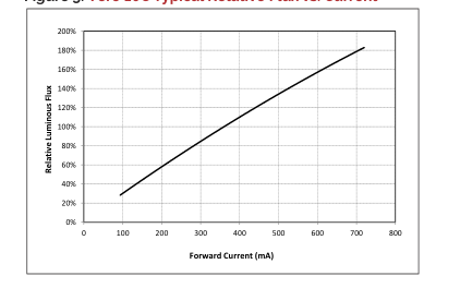
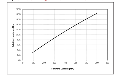
Vero LED arrays are tested to the specifications shown using the nominal drive currents in Table 1. Vero may also be driven at other drive currents dependent on specific application design requirements. The performance at any drive current can be derived from the current vs. voltage characteristics shown in Figures 1, 2 & 3 and the flux vs. current characteristics shown in Figures 4, 5 & 6. The performance at commonly used drive currents is summarized in Table 5.
Table 5: Product Performance at Commonly Used Drive Currents
| Part Number | CRI | Drive Current1 (mA) | Typical V f T = 25ºC c (V) | Typical Power T = 25ºC c (W) | Typical Flux2 T = 25ºC c (lm) | Typical DC Flux3 T = 85ºC c (lm) | Typical Efficacy T = 25ºC c (lm/W) |
|---|---|---|---|---|---|---|---|
| BXRC-20B1001-B-7x | 65 | 135 | 33.2 | 4.5 | 762 | 685 | 170 |
| 180 | 34.0 | 6.1 | 1000 | 897 | 163 | ||
| 270 | 34.8 | 9.4 | 1431 | 1288 | 152 | ||
| 405 | 35.6 | 14.4 | 2099 | 1867 | 145 | ||
| 540 | 36.1 | 19.5 | 2689 | 2380 | 138 | ||
| BXRC-20B1001-D-7x | 65 | 175 | 24.9 | 4.4 | 740 | 673 | 170 |
| 233 | 25.4 | 5.9 | 971 | 873 | 164 | ||
| 350 | 26.0 | 9.1 | 1386 | 1247 | 152 | ||
| 525 | 27.4 | 14.4 | 2040 | 1759 | 142 | ||
| 700 | 28.4 | 19.9 | 2613 | 2201 | 131 | ||
| BXRC-27E1000-B-7x | 80 | 135 | 33.2 | 4.5 | 777 | 698 | 173 |
| 180 | 34.0 | 6.1 | 1019 | 914 | 166 | ||
| 270 | 34.8 | 9.4 | 1458 | 1312 | 155 | ||
| 405 | 35.6 | 14.4 | 2139 | 1903 | 148 | ||
| 540 | 36.1 | 19.5 | 2741 | 2426 | 140 | ||
| BXRC-27E1000-C-7x | 80 | 180 | 33.2 | 6.0 | 1034 | 922 | 173 |
| 240 | 34.0 | 8.2 | 1354 | 1203 | 166 | ||
| 360 | 34.8 | 12.5 | 1944 | 1750 | 155 | ||
| 540 | 35.6 | 19.2 | 2831 | 2460 | 147 | ||
| 720 | 36.1 | 26.0 | 3617 | 3096 | 139 | ||
| BXRC-27E1000-D-7x | 80 | 175 | 24.9 | 4.4 | 754 | 686 | 173 |
| 233 | 25.4 | 5.9 | 989 | 889 | 167 | ||
| 350 | 26.0 | 9.1 | 1412 | 1271 | 155 | ||
| 525 | 27.4 | 14.4 | 2079 | 1793 | 145 | ||
| 700 | 28.4 | 19.9 | 2663 | 2243 | 134 | ||
| BXRC-27G10H0-B-7x | 90 | 135 | 33.2 | 4.5 | 665 | 598 | 148 |
| 180 | 34.0 | 6.1 | 872 | 783 | 143 | ||
| 270 | 34.8 | 9.4 | 1249 | 1124 | 133 | ||
| 405 | 35.6 | 14.4 | 1832 | 1630 | 127 | ||
| 540 | 36.1 | 19.5 | 2347 | 2077 | 120 | ||
| BXRC-27G10H0-C-7x | 90 | 180 | 33.2 | 6.0 | 885 | 790 | 148 |
| 240 | 34.0 | 8.2 | 1160 | 1030 | 142 | ||
| 360 | 34.8 | 12.5 | 1665 | 1498 | 133 | ||
| 540 | 35.6 | 19.2 | 2424 | 2106 | 126 | ||
| 720 | 36.1 | 26.0 | 3097 | 2651 | 119 | ||
| BXRC-27G10H0-D-7x | 90 | 175 | 24.9 | 4.4 | 646 | 587 | 148 |
| 233 | 25.4 | 5.9 | 847 | 762 | 143 | ||
| 350 | 26.0 | 9.1 | 1209 | 1088 | 133 | ||
| 525 | 27.4 | 14.4 | 1780 | 1535 | 124 | ||
| 700 | 28.4 | 19.9 | 2280 | 1920 | 115 |
Notes for Table 5: 1. Alternate drive currents are provided for reference only and are not a guarantee of performance. 2. Bridgelux maintains a ± 7% tolerance on flux measurements. 3. Typical stabilized DC performance values are provided as reference only and are not a guarantee of performance.
Page 16

Table 5: Product Performance at Commonly Used Drive Currents (Continued)
| Part Number | CRI | Drive Current1 (mA) | Typical V f T = 25ºC c (V) | Typical Power T = 25ºC c (W) | Typical Flux2 T = 25ºC c (lm) | Typical DC Flux3 T = 85ºC c (lm) | Typical Efficacy T = 25ºC c (lm/W) |
|---|---|---|---|---|---|---|---|
| BXRC-27G1000-B-7x | 90 | 135 | 33.2 | 4.5 | 641 | 576 | 143 |
| 180 | 34.0 | 6.1 | 841 | 754 | 137 | ||
| 270 | 34.8 | 9.4 | 1203 | 1083 | 128 | ||
| 405 | 35.6 | 14.4 | 1765 | 1570 | 122 | ||
| 540 | 36.1 | 19.5 | 2261 | 2001 | 116 | ||
| BXRC-27G1000-C-7x | 90 | 180 | 33.2 | 6.0 | 853 | 761 | 143 |
| 240 | 34.0 | 8.2 | 1117 | 993 | 137 | ||
| 360 | 34.8 | 12.5 | 1604 | 1444 | 128 | ||
| 540 | 35.6 | 19.2 | 2336 | 2029 | 121 | ||
| 720 | 36.1 | 26.0 | 2984 | 2554 | 115 | ||
| BXRC-27G1000-D-7x | 90 | 175 | 24.9 | 4.4 | 622 | 566 | 143 |
| 233 | 25.4 | 5.9 | 816 | 734 | 138 | ||
| 350 | 26.0 | 9.1 | 1165 | 1049 | 128 | ||
| 525 | 27.4 | 14.4 | 1715 | 1479 | 119 | ||
| 700 | 28.4 | 19.9 | 2197 | 1850 | 110 | ||
| BXRC-27H1000-B-7x | 97 | 135 | 33.2 | 4.5 | 568 | 511 | 127 |
| 180 | 34.0 | 6.1 | 745 | 668 | 122 | ||
| 270 | 34.8 | 9.4 | 1066 | 960 | 113 | ||
| 405 | 35.6 | 14.4 | 1564 | 1392 | 108 | ||
| 540 | 36.1 | 19.5 | 2004 | 1774 | 103 | ||
| BXRC-27H1000-C-7x | 97 | 180 | 33.2 | 6.0 | 756 | 675 | 126 |
| 240 | 34.0 | 8.2 | 990 | 880 | 121 | ||
| 360 | 34.8 | 12.5 | 1422 | 1280 | 113 | ||
| 540 | 35.6 | 19.2 | 2070 | 1799 | 108 | ||
| 720 | 36.1 | 26.0 | 2645 | 2264 | 102 | ||
| BXRC-27H1000-D-7x | 97 | 175 | 24.9 | 4.4 | 551 | 501 | 126 |
| 233 | 25.4 | 5.9 | 723 | 650 | 122 | ||
| 350 | 26.0 | 9.1 | 1033 | 929 | 113 | ||
| 525 | 27.4 | 14.4 | 1520 | 1311 | 106 | ||
| 700 | 28.4 | 19.9 | 1948 | 1640 | 98 | ||
| BXRC-30C1001-B-7x | 70 | 135 | 33.2 | 4.5 | 864 | 777 | 193 |
| 180 | 34.0 | 6.1 | 1134 | 1017 | 185 | ||
| 270 | 34.8 | 9.4 | 1622 | 1460 | 173 | ||
| 405 | 35.6 | 14.4 | 2380 | 2117 | 165 | ||
| 540 | 36.1 | 19.5 | 3049 | 2699 | 156 | ||
| BXRC-30C1001-C-7x | 70 | 180 | 33.2 | 6.0 | 1150 | 1026 | 192 |
| 240 | 34.0 | 8.2 | 1507 | 1338 | 185 | ||
| 360 | 34.8 | 12.5 | 2163 | 1947 | 173 | ||
| 540 | 35.6 | 19.2 | 3150 | 2736 | 164 | ||
| 720 | 36.1 | 26.0 | 4023 | 3444 | 155 | ||
| BXRC-30C1001-D-7x | 70 | 175 | 24.9 | 4.4 | 839 | 763 | 192 |
| 233 | 25.4 | 5.9 | 1101 | 990 | 186 | ||
| 350 | 26.0 | 9.1 | 1571 | 1414 | 173 | ||
| 525 | 27.4 | 14.4 | 2313 | 1995 | 161 | ||
| 700 | 28.4 | 19.9 | 2963 | 2495 | 149 |
Notes for Table 5: 1. Alternate drive currents are provided for reference only and are not a guarantee of performance. 2. Bridgelux maintains a ± 7% tolerance on flux measurements. 3. Typical stabilized DC performance values are provided as reference only and are not a guarantee of performance.
Page 17

Table 5: Product Performance at Commonly Used Drive Currents (Continued)
| Part Number | CRI | Drive Current1 (mA) | Typical V f T = 25ºC c (V) | Typical Power T = 25ºC c (W) | Typical Flux2 T = 25ºC c (lm) | Typical DC Flux3 T = 85ºC c (lm) | Typical Efficacy T = 25ºC c (lm/W) |
|---|---|---|---|---|---|---|---|
| BXRC-30E1000-B-7x | 80 | 135 | 33.2 | 4.5 | 826 | 742 | 184 |
| 180 | 34.0 | 6.1 | 1083 | 971 | 177 | ||
| 270 | 34.8 | 9.4 | 1549 | 1394 | 165 | ||
| 405 | 35.6 | 14.4 | 2273 | 2022 | 157 | ||
| 540 | 36.1 | 19.5 | 2912 | 2577 | 149 | ||
| BXRC-30E1000-C-7x | 80 | 180 | 33.2 | 6.0 | 1098 | 980 | 184 |
| 240 | 34.0 | 8.2 | 1439 | 1278 | 176 | ||
| 360 | 34.8 | 12.5 | 2066 | 1859 | 165 | ||
| 540 | 35.6 | 19.2 | 3008 | 2613 | 156 | ||
| 720 | 36.1 | 26.0 | 3843 | 3289 | 148 | ||
| BXRC-30E1000-D-7x | 80 | 175 | 24.9 | 4.4 | 801 | 729 | 184 |
| 233 | 25.4 | 5.9 | 1051 | 945 | 178 | ||
| 350 | 26.0 | 9.1 | 1501 | 1351 | 165 | ||
| 525 | 27.4 | 14.4 | 2209 | 1905 | 154 | ||
| 700 | 28.4 | 19.9 | 2830 | 2383 | 142 | ||
| BXRC-30G10H0-B-7x | 90 | 135 | 33.2 | 4.5 | 699 | 628 | 156 |
| 180 | 34.0 | 6.1 | 917 | 823 | 150 | ||
| 270 | 34.8 | 9.4 | 1312 | 1181 | 140 | ||
| 405 | 35.6 | 14.4 | 1925 | 1713 | 133 | ||
| 540 | 36.1 | 19.5 | 2467 | 2183 | 126 | ||
| BXRC-30G10H0-C-7x | 90 | 180 | 33.2 | 6.0 | 930 | 830 | 156 |
| 240 | 34.0 | 8.2 | 1219 | 1083 | 149 | ||
| 360 | 34.8 | 12.5 | 1750 | 1575 | 140 | ||
| 540 | 35.6 | 19.2 | 2548 | 2214 | 132 | ||
| 720 | 36.1 | 26.0 | 3255 | 2786 | 125 | ||
| BXRC-30G10H0-D-7x | 90 | 175 | 24.9 | 4.4 | 679 | 617 | 156 |
| 233 | 25.4 | 5.9 | 890 | 801 | 150 | ||
| 350 | 26.0 | 9.1 | 1271 | 1144 | 140 | ||
| 525 | 27.4 | 14.4 | 1871 | 1614 | 130 | ||
| 700 | 28.4 | 19.9 | 2397 | 2018 | 121 | ||
| BXRC-30G1000-B-7x | 90 | 135 | 33.2 | 4.5 | 670 | 602 | 149 |
| 180 | 34.0 | 6.1 | 879 | 788 | 144 | ||
| 270 | 34.8 | 9.4 | 1258 | 1132 | 134 | ||
| 405 | 35.6 | 14.4 | 1845 | 1641 | 128 | ||
| 540 | 36.1 | 19.5 | 2364 | 2092 | 121 | ||
| BXRC-30G1000-C-7x | 90 | 180 | 33.2 | 6.0 | 892 | 796 | 149 |
| 240 | 34.0 | 8.2 | 1168 | 1038 | 143 | ||
| 360 | 34.8 | 12.5 | 1677 | 1509 | 134 | ||
| 540 | 35.6 | 19.2 | 2442 | 2121 | 127 | ||
| 720 | 36.1 | 26.0 | 3119 | 2670 | 120 | ||
| BXRC-30G1000-D-7x | 90 | 175 | 24.9 | 4.4 | 650 | 591 | 149 |
| 233 | 25.4 | 5.9 | 853 | 767 | 144 | ||
| 350 | 26.0 | 9.1 | 1218 | 1096 | 134 | ||
| 525 | 27.4 | 14.4 | 1793 | 1546 | 125 | ||
| 700 | 28.4 | 19.9 | 2297 | 1934 | 115 |
Notes for Table 5: 1. Alternate drive currents are provided for reference only and are not a guarantee of performance. 2. Bridgelux maintains a ± 7% tolerance on flux measurements. 3. Typical stabilized DC performance values are provided as reference only and are not a guarantee of performance.
Page 18

Table 5: Product Performance at Commonly Used Drive Currents (Continued)
| Part Number | CRI | Drive Current1 (mA) | Typical V f T = 25ºC c (V) | Typical Power T = 25ºC c (W) | Typical Flux2 T = 25ºC c (lm) | Typical DC Flux3 T = 85ºC c (lm) | Typical Efficacy T = 25ºC c (lm/W) |
|---|---|---|---|---|---|---|---|
| BXRC-30G100C-B-7x | 90 | 135 | 33.2 | 4.5 | 646 | 580 | 144 |
| 180 | 34.0 | 6.1 | 847 | 760 | 138 | ||
| 270 | 34.8 | 9.4 | 1212 | 1091 | 129 | ||
| 405 | 35.6 | 14.4 | 1778 | 1582 | 123 | ||
| 540 | 36.1 | 19.5 | 2278 | 2016 | 117 | ||
| BXRC-30G100C-D-7x | 90 | 175 | 24.9 | 4.4 | 627 | 570 | 144 |
| 233 | 25.4 | 5.9 | 822 | 739 | 139 | ||
| 350 | 26.0 | 9.1 | 1174 | 1057 | 129 | ||
| 525 | 27.4 | 14.4 | 1728 | 1490 | 120 | ||
| 700 | 28.4 | 19.9 | 2214 | 1864 | 111 | ||
| BXRC-30H1000-B-7x | 97 | 135 | 33.2 | 4.5 | 607 | 546 | 135 |
| 180 | 34.0 | 6.1 | 796 | 714 | 130 | ||
| 270 | 34.8 | 9.4 | 1139 | 1025 | 121 | ||
| 405 | 35.6 | 14.4 | 1671 | 1487 | 116 | ||
| 540 | 36.1 | 19.5 | 2141 | 1895 | 110 | ||
| BXRC-30H1000-C-7x | 97 | 180 | 33.2 | 6.0 | 808 | 721 | 135 |
| 240 | 34.0 | 8.2 | 1058 | 940 | 130 | ||
| 360 | 34.8 | 12.5 | 1519 | 1367 | 121 | ||
| 540 | 35.6 | 19.2 | 2212 | 1922 | 115 | ||
| 720 | 36.1 | 26.0 | 2825 | 2419 | 109 | ||
| BXRC-30H1000-D-7x | 97 | 175 | 24.9 | 4.4 | 589 | 536 | 135 |
| 233 | 25.4 | 5.9 | 773 | 695 | 131 | ||
| 350 | 26.0 | 9.1 | 1103 | 993 | 121 | ||
| 525 | 27.4 | 14.4 | 1624 | 1401 | 113 | ||
| 700 | 28.4 | 19.9 | 2081 | 1752 | 105 | ||
| BXRC-30A1001-B-7x | 93 | 135 | 33.2 | 4.5 | 602 | 541 | 134 |
| 180 | 34.0 | 6.1 | 790 | 708 | 129 | ||
| 270 | 34.8 | 9.4 | 1130 | 1017 | 120 | ||
| 405 | 35.6 | 14.4 | 1658 | 1475 | 115 | ||
| 540 | 36.1 | 19.5 | 2124 | 1880 | 109 | ||
| BXRC-30A1001-C-7x | 93 | 180 | 33.2 | 6.0 | 801 | 715 | 134 |
| 240 | 34.0 | 8.2 | 1050 | 932 | 129 | ||
| 360 | 34.8 | 12.5 | 1507 | 1356 | 120 | ||
| 540 | 35.6 | 19.2 | 2194 | 1906 | 114 | ||
| 720 | 36.1 | 26.0 | 2803 | 2399 | 108 | ||
| BXRC-30A1001-D-7x | 93 | 175 | 24.9 | 4.4 | 584 | 531 | 134 |
| 233 | 25.4 | 5.9 | 767 | 689 | 130 | ||
| 350 | 26.0 | 9.1 | 1095 | 985 | 120 | ||
| 525 | 27.4 | 14.4 | 1611 | 1390 | 112 | ||
| 700 | 28.4 | 19.9 | 2064 | 1738 | 104 | ||
| BXRC-35E1000-B-7x | 80 | 135 | 33.2 | 4.5 | 845 | 759 | 188 |
| 180 | 34.0 | 6.1 | 1108 | 994 | 181 | ||
| 270 | 34.8 | 9.4 | 1586 | 1427 | 169 | ||
| 405 | 35.6 | 14.4 | 2327 | 2070 | 161 | ||
| 540 | 36.1 | 19.5 | 2981 | 2638 | 153 |
Notes for Table 5: 1. Alternate drive currents are provided for reference only and are not a guarantee of performance. 2. Bridgelux maintains a ± 7% tolerance on flux measurements. 3. Typical stabilized DC performance values are provided as reference only and are not a guarantee of performance.
Page 19

Table 5: Product Performance at Commonly Used Drive Currents (Continued)
| Part Number | CRI | Drive Current1 (mA) | Typical V f T = 25ºC c (V) | Typical Power T = 25ºC c (W) | Typical Flux2 T = 25ºC c (lm) | Typical DC Flux3 T = 85ºC c (lm) | Typical Efficacy T = 25ºC c (lm/W) |
|---|---|---|---|---|---|---|---|
| BXRC-35E1000-C-7x | 80 | 180 | 33.2 | 6.0 | 1124 | 1003 | 188 |
| 240 | 34.0 | 8.2 | 1473 | 1308 | 180 | ||
| 360 | 34.8 | 12.5 | 2114 | 1903 | 169 | ||
| 540 | 35.6 | 19.2 | 3079 | 2675 | 160 | ||
| 720 | 36.1 | 26.0 | 3933 | 3367 | 151 | ||
| BXRC-35E1000-D-7x | 80 | 175 | 24.9 | 4.4 | 820 | 746 | 188 |
| 233 | 25.4 | 5.9 | 1076 | 967 | 182 | ||
| 350 | 26.0 | 9.1 | 1536 | 1382 | 169 | ||
| 525 | 27.4 | 14.4 | 2261 | 1950 | 157 | ||
| 700 | 28.4 | 19.9 | 2896 | 2439 | 146 | ||
| BXRC-35G1000-B-7x | 90 | 135 | 33.2 | 4.5 | 695 | 624 | 155 |
| 180 | 34.0 | 6.1 | 911 | 817 | 149 | ||
| 270 | 34.8 | 9.4 | 1303 | 1173 | 139 | ||
| 405 | 35.6 | 14.4 | 1912 | 1701 | 132 | ||
| 540 | 36.1 | 19.5 | 2450 | 2168 | 126 | ||
| BXRC-35G1000-C-7x | 90 | 180 | 33.2 | 6.0 | 924 | 824 | 155 |
| 240 | 34.0 | 8.2 | 1210 | 1075 | 148 | ||
| 360 | 34.8 | 12.5 | 1738 | 1564 | 139 | ||
| 540 | 35.6 | 19.2 | 2530 | 2198 | 131 | ||
| 720 | 36.1 | 26.0 | 3232 | 2767 | 124 | ||
| BXRC-35G1000-D-7x | 90 | 175 | 24.9 | 4.4 | 674 | 613 | 155 |
| 233 | 25.4 | 5.9 | 884 | 795 | 149 | ||
| 350 | 26.0 | 9.1 | 1262 | 1136 | 139 | ||
| 525 | 27.4 | 14.4 | 1858 | 1602 | 129 | ||
| 700 | 28.4 | 19.9 | 2380 | 2004 | 120 | ||
| BXRC-35A1001-B-7x | 93 | 135 | 33.2 | 4.5 | 641 | 576 | 143 |
| 180 | 34.0 | 6.1 | 841 | 754 | 137 | ||
| 270 | 34.8 | 9.4 | 1203 | 1083 | 128 | ||
| 405 | 35.6 | 14.4 | 1765 | 1570 | 122 | ||
| 540 | 36.1 | 19.5 | 2261 | 2001 | 116 | ||
| BXRC-35A1001-C-7x | 93 | 180 | 33.2 | 6.0 | 853 | 761 | 143 |
| 240 | 34.0 | 8.2 | 1117 | 993 | 137 | ||
| 360 | 34.8 | 12.5 | 1604 | 1444 | 128 | ||
| 540 | 35.6 | 19.2 | 2336 | 2029 | 121 | ||
| 720 | 36.1 | 26.0 | 2984 | 2554 | 115 | ||
| BXRC-35A1001-D-7x | 93 | 175 | 24.9 | 4.4 | 622 | 566 | 143 |
| 233 | 25.4 | 5.9 | 816 | 734 | 138 | ||
| 350 | 26.0 | 9.1 | 1165 | 1049 | 128 | ||
| 525 | 27.4 | 14.4 | 1715 | 1479 | 119 | ||
| 700 | 28.4 | 19.9 | 2197 | 1850 | 110 | ||
| BXRC-40C1001-B-7x | 70 | 135 | 33.2 | 4.5 | 889 | 799 | 198 |
| 180 | 34.0 | 6.1 | 1165 | 1045 | 190 | ||
| 270 | 34.8 | 9.4 | 1668 | 1501 | 178 | ||
| 405 | 35.6 | 14.4 | 2447 | 2177 | 170 | ||
| 540 | 36.1 | 19.5 | 3135 | 2775 | 161 |
Notes for Table 5: 1. Alternate drive currents are provided for reference only and are not a guarantee of performance. 2. Bridgelux maintains a ± 7% tolerance on flux measurements. 3. Typical stabilized DC performance values are provided as reference only and are not a guarantee of performance.
Page 20

Table 5: Product Performance at Commonly Used Drive Currents (Continued)
| Part Number | CRI | Drive Current1 (mA) | Typical V f T = 25ºC c (V) | Typical Power T = 25ºC c (W) | Typical Flux2 T = 25ºC c (lm) | Typical DC Flux3 T = 85ºC c (lm) | Typical Efficacy T = 25ºC c (lm/W) |
|---|---|---|---|---|---|---|---|
| BXRC-40C1001-C-7x | 70 | 180 | 33.2 | 6.0 | 1182 | 1055 | 198 |
| 240 | 34.0 | 8.2 | 1549 | 1376 | 190 | ||
| 360 | 34.8 | 12.5 | 2224 | 2001 | 178 | ||
| 540 | 35.6 | 19.2 | 3238 | 2813 | 168 | ||
| 720 | 36.1 | 26.0 | 4136 | 3541 | 159 | ||
| BXRC-40C1001-D-7x | 70 | 175 | 24.9 | 4.4 | 862 | 784 | 198 |
| 233 | 25.4 | 5.9 | 1131 | 1017 | 191 | ||
| 350 | 26.0 | 9.1 | 1615 | 1454 | 178 | ||
| 525 | 27.4 | 14.4 | 2378 | 2051 | 165 | ||
| 700 | 28.4 | 19.9 | 3046 | 2565 | 153 | ||
| BXRC-40E1000-B-7x | 80 | 135 | 33.2 | 4.5 | 850 | 764 | 190 |
| 180 | 34.0 | 6.1 | 1114 | 1000 | 182 | ||
| 270 | 34.8 | 9.4 | 1595 | 1435 | 170 | ||
| 405 | 35.6 | 14.4 | 2340 | 2082 | 162 | ||
| 540 | 36.1 | 19.5 | 2998 | 2653 | 154 | ||
| BXRC-40E1000-C-7x | 80 | 180 | 33.2 | 6.0 | 1131 | 1009 | 189 |
| 240 | 34.0 | 8.2 | 1481 | 1316 | 181 | ||
| 360 | 34.8 | 12.5 | 2127 | 1914 | 170 | ||
| 540 | 35.6 | 19.2 | 3097 | 2690 | 161 | ||
| 720 | 36.1 | 26.0 | 3956 | 3386 | 152 | ||
| BXRC-40E1000-D-7x | 80 | 175 | 24.9 | 4.4 | 825 | 750 | 189 |
| 233 | 25.4 | 5.9 | 1082 | 973 | 183 | ||
| 350 | 26.0 | 9.1 | 1545 | 1390 | 170 | ||
| 525 | 27.4 | 14.4 | 2274 | 1961 | 158 | ||
| 700 | 28.4 | 19.9 | 2913 | 2453 | 146 | ||
| BXRC-40G1000-B-7x | 90 | 135 | 33.2 | 4.5 | 709 | 637 | 158 |
| 180 | 34.0 | 6.1 | 930 | 834 | 152 | ||
| 270 | 34.8 | 9.4 | 1331 | 1198 | 142 | ||
| 405 | 35.6 | 14.4 | 1952 | 1737 | 135 | ||
| 540 | 36.1 | 19.5 | 2501 | 2214 | 128 | ||
| BXRC-40G1000-C-7x | 90 | 180 | 33.2 | 6.0 | 943 | 842 | 158 |
| 240 | 34.0 | 8.2 | 1236 | 1098 | 151 | ||
| 360 | 34.8 | 12.5 | 1774 | 1597 | 142 | ||
| 540 | 35.6 | 19.2 | 2584 | 2244 | 134 | ||
| 720 | 36.1 | 26.0 | 3300 | 2825 | 127 | ||
| BXRC-40G1000-D-7x | 90 | 175 | 24.9 | 4.4 | 688 | 626 | 158 |
| 233 | 25.4 | 5.9 | 903 | 812 | 153 | ||
| 350 | 26.0 | 9.1 | 1289 | 1160 | 142 | ||
| 525 | 27.4 | 14.4 | 1897 | 1636 | 132 | ||
| 700 | 28.4 | 19.9 | 2430 | 2047 | 122 | ||
| BXRC-40H1000-B-7x | 97 | 135 | 33.2 | 4.5 | 641 | 576 | 143 |
| 180 | 34.0 | 6.1 | 841 | 754 | 137 | ||
| 270 | 34.8 | 9.4 | 1203 | 1083 | 128 | ||
| 405 | 35.6 | 14.4 | 1765 | 1570 | 122 | ||
| 540 | 36.1 | 19.5 | 2261 | 2001 | 116 |
Notes for Table 5: 1. Alternate drive currents are provided for reference only and are not a guarantee of performance. 2. Bridgelux maintains a ± 7% tolerance on flux measurements. 3. Typical stabilized DC performance values are provided as reference only and are not a guarantee of performance.
Page 21

Table 5: Product Performance at Commonly Used Drive Currents (Continued)
| Part Number | CRI | Drive Current1 (mA) | Typical V f T = 25ºC c (V) | Typical Power T = 25ºC c (W) | Typical Flux2 T = 25ºC c (lm) | Typical DC Flux3 T = 85ºC c (lm) | Typical Efficacy T = 25ºC c (lm/W) |
|---|---|---|---|---|---|---|---|
| BXRC-40H1000-C-7x | 97 | 180 | 33.2 | 6.0 | 853 | 761 | 143 |
| 240 | 34.0 | 8.2 | 1117 | 993 | 137 | ||
| 360 | 34.8 | 12.5 | 1604 | 1444 | 128 | ||
| 540 | 35.6 | 19.2 | 2336 | 2029 | 121 | ||
| 720 | 36.1 | 26.0 | 2984 | 2554 | 115 | ||
| BXRC-40H1000-D-7x | 97 | 175 | 24.9 | 4.4 | 622 | 566 | 143 |
| 233 | 25.4 | 5.9 | 816 | 734 | 138 | ||
| 350 | 26.0 | 9.1 | 1165 | 1049 | 128 | ||
| 525 | 27.4 | 14.4 | 1715 | 1479 | 119 | ||
| 700 | 28.4 | 19.9 | 2197 | 1850 | 110 | ||
| BXRC-40A1001-B-7x | 93 | 135 | 33.2 | 4.5 | 695 | 624 | 155 |
| 180 | 34.0 | 6.1 | 911 | 817 | 149 | ||
| 270 | 34.8 | 9.4 | 1303 | 1173 | 139 | ||
| 405 | 35.6 | 14.4 | 1912 | 1701 | 132 | ||
| 540 | 36.1 | 19.5 | 2450 | 2168 | 126 | ||
| BXRC-40A1001-C-7x | 93 | 180 | 33.2 | 6.0 | 924 | 824 | 155 |
| 240 | 34.0 | 8.2 | 1210 | 1075 | 148 | ||
| 360 | 34.8 | 12.5 | 1738 | 1564 | 139 | ||
| 540 | 35.6 | 19.2 | 2530 | 2198 | 131 | ||
| 720 | 36.1 | 26.0 | 3232 | 2767 | 124 | ||
| BXRC-40A1001-D-7x | 93 | 175 | 24.9 | 4.4 | 674 | 613 | 155 |
| 233 | 25.4 | 5.9 | 884 | 795 | 149 | ||
| 350 | 26.0 | 9.1 | 1262 | 1136 | 139 | ||
| 525 | 27.4 | 14.4 | 1858 | 1602 | 129 | ||
| 700 | 28.4 | 19.9 | 2380 | 2004 | 120 | ||
| BXRC-50C1001-B-7x | 70 | 135 | 33.2 | 4.5 | 894 | 803 | 199 |
| 180 | 34.0 | 6.1 | 1172 | 1051 | 191 | ||
| 270 | 34.8 | 9.4 | 1677 | 1509 | 178 | ||
| 405 | 35.6 | 14.4 | 2460 | 2189 | 170 | ||
| 540 | 36.1 | 19.5 | 3152 | 2790 | 161 | ||
| BXRC-50C1001-C-7x | 70 | 180 | 33.2 | 6.0 | 1189 | 1061 | 199 |
| 240 | 34.0 | 8.2 | 1557 | 1384 | 191 | ||
| 360 | 34.8 | 12.5 | 2236 | 2012 | 178 | ||
| 540 | 35.6 | 19.2 | 3256 | 2828 | 169 | ||
| 720 | 36.1 | 26.0 | 4159 | 3560 | 160 | ||
| BXRC-50C1001-D-7x | 70 | 175 | 24.9 | 4.4 | 867 | 789 | 199 |
| 233 | 25.4 | 5.9 | 1138 | 1023 | 192 | ||
| 350 | 26.0 | 9.1 | 1624 | 1462 | 178 | ||
| 525 | 27.4 | 14.4 | 2391 | 2062 | 166 | ||
| 700 | 28.4 | 19.9 | 3063 | 2579 | 154 | ||
| BXRC-50E1001-B-7x | 80 | 135 | 33.2 | 4.5 | 860 | 773 | 192 |
| 180 | 34.0 | 6.1 | 1127 | 1011 | 184 | ||
| 270 | 34.8 | 9.4 | 1613 | 1452 | 172 | ||
| 405 | 35.6 | 14.4 | 2367 | 2105 | 164 | ||
| 540 | 36.1 | 19.5 | 3032 | 2684 | 155 |
Notes for Table 5: 1. Alternate drive currents are provided for reference only and are not a guarantee of performance. 2. Bridgelux maintains a ± 7% tolerance on flux measurements. 3. Typical stabilized DC performance values are provided as reference only and are not a guarantee of performance.
Page 22

Table 5: Product Performance at Commonly Used Drive Currents (Continued)
| Part Number | CRI | Drive Current1 (mA) | Typical V f T = 25ºC c (V) | Typical Power T = 25ºC c (W) | Typical Flux2 T = 25ºC c (lm) | Typical DC Flux3 T = 85ºC c (lm) | Typical Efficacy T = 25ºC c (lm/W) |
|---|---|---|---|---|---|---|---|
| BXRC-50E1001-C-7x | 80 | 180 | 33.2 | 6.0 | 1144 | 1020 | 191 |
| 240 | 34.0 | 8.2 | 1498 | 1331 | 184 | ||
| 360 | 34.8 | 12.5 | 2151 | 1936 | 172 | ||
| 540 | 35.6 | 19.2 | 3132 | 2721 | 163 | ||
| 720 | 36.1 | 26.0 | 4001 | 3425 | 154 | ||
| BXRC-50E1001-D-7x | 80 | 175 | 24.9 | 4.4 | 834 | 759 | 191 |
| 233 | 25.4 | 5.9 | 1094 | 984 | 185 | ||
| 350 | 26.0 | 9.1 | 1562 | 1406 | 172 | ||
| 525 | 27.4 | 14.4 | 2300 | 1983 | 160 | ||
| 700 | 28.4 | 19.9 | 2946 | 2481 | 148 | ||
| BXRC-50G1001-B-7x | 90 | 135 | 33.2 | 4.5 | 743 | 668 | 166 |
| 180 | 34.0 | 6.1 | 974 | 874 | 159 | ||
| 270 | 34.8 | 9.4 | 1394 | 1255 | 148 | ||
| 405 | 35.6 | 14.4 | 2046 | 1820 | 142 | ||
| 540 | 36.1 | 19.5 | 2621 | 2320 | 134 | ||
| BXRC-50G1001-C-7x | 90 | 180 | 33.2 | 6.0 | 989 | 882 | 165 |
| 240 | 34.0 | 8.2 | 1295 | 1150 | 159 | ||
| 360 | 34.8 | 12.5 | 1859 | 1673 | 148 | ||
| 540 | 35.6 | 19.2 | 2707 | 2352 | 141 | ||
| 720 | 36.1 | 26.0 | 3458 | 2960 | 133 | ||
| BXRC-50G1001-D-7x | 90 | 175 | 24.9 | 4.4 | 721 | 656 | 165 |
| 233 | 25.4 | 5.9 | 946 | 851 | 160 | ||
| 350 | 26.0 | 9.1 | 1351 | 1215 | 148 | ||
| 525 | 27.4 | 14.4 | 1988 | 1714 | 138 | ||
| 700 | 28.4 | 19.9 | 2547 | 2145 | 128 | ||
| BXRC-57C1001-B-7x | 70 | 135 | 33.2 | 4.5 | 869 | 781 | 194 |
| 180 | 34.0 | 6.1 | 1140 | 1022 | 186 | ||
| 270 | 34.8 | 9.4 | 1631 | 1468 | 174 | ||
| 405 | 35.6 | 14.4 | 2393 | 2129 | 166 | ||
| 540 | 36.1 | 19.5 | 3066 | 2714 | 157 | ||
| BXRC-57C1001-C-7x | 70 | 180 | 33.2 | 6.0 | 1156 | 1032 | 193 |
| 240 | 34.0 | 8.2 | 1515 | 1346 | 186 | ||
| 360 | 34.8 | 12.5 | 2175 | 1958 | 174 | ||
| 540 | 35.6 | 19.2 | 3167 | 2752 | 165 | ||
| 720 | 36.1 | 26.0 | 4046 | 3463 | 155 | ||
| BXRC-57C1001-D-7x | 70 | 175 | 24.9 | 4.4 | 844 | 767 | 193 |
| 233 | 25.4 | 5.9 | 1107 | 995 | 187 | ||
| 350 | 26.0 | 9.1 | 1580 | 1422 | 174 | ||
| 525 | 27.4 | 14.4 | 2326 | 2006 | 162 | ||
| 700 | 28.4 | 19.9 | 2980 | 2509 | 150 | ||
| BXRC-57E1001-B-7x | 80 | 135 | 33.2 | 4.5 | 826 | 742 | 184 |
| 180 | 34.0 | 6.1 | 1083 | 971 | 177 | ||
| 270 | 34.8 | 9.4 | 1549 | 1394 | 165 | ||
| 405 | 35.6 | 14.4 | 2273 | 2022 | 157 | ||
| 540 | 36.1 | 19.5 | 2912 | 2577 | 149 |
Notes for Table 5: 1. Alternate drive currents are provided for reference only and are not a guarantee of performance. 2. Bridgelux maintains a ± 7% tolerance on flux measurements. 3. Typical stabilized DC performance values are provided as reference only and are not a guarantee of performance.
Page 23

Table 5: Product Performance at Commonly Used Drive Currents (Continued)
| Part Number | CRI | Drive Current1 (mA) | Typical V f T = 25ºC c (V) | Typical Power T = 25ºC c (W) | Typical Flux2 T = 25ºC c (lm) | Typical DC Flux3 T = 85ºC c (lm) | Typical Efficacy T = 25ºC c (lm/W) |
|---|---|---|---|---|---|---|---|
| BXRC-57E1001-C-7x | 80 | 180 | 33.2 | 6.0 | 1098 | 980 | 184 |
| 240 | 34.0 | 8.2 | 1439 | 1278 | 176 | ||
| 360 | 34.8 | 12.5 | 2066 | 1859 | 165 | ||
| 540 | 35.6 | 19.2 | 3008 | 2613 | 156 | ||
| 720 | 36.1 | 26.0 | 3843 | 3289 | 148 | ||
| BXRC-57E1001-D-7x | 80 | 175 | 24.9 | 4.4 | 801 | 729 | 184 |
| 233 | 25.4 | 5.9 | 1051 | 945 | 178 | ||
| 350 | 26.0 | 9.1 | 1501 | 1351 | 165 | ||
| 525 | 27.4 | 14.4 | 2209 | 1905 | 154 | ||
| 700 | 28.4 | 19.9 | 2830 | 2383 | 142 | ||
| BXRC-65C1001-B-7x | 70 | 135 | 33.2 | 4.5 | 869 | 781 | 194 |
| 180 | 34.0 | 6.1 | 1140 | 1022 | 186 | ||
| 270 | 34.8 | 9.4 | 1631 | 1468 | 174 | ||
| 405 | 35.6 | 14.4 | 2393 | 2129 | 166 | ||
| 540 | 36.1 | 19.5 | 3066 | 2714 | 157 | ||
| BXRC-65C1001-C-7x | 70 | 180 | 33.2 | 6.0 | 1156 | 1032 | 193 |
| 240 | 34.0 | 8.2 | 1515 | 1346 | 186 | ||
| 360 | 34.8 | 12.5 | 2175 | 1958 | 174 | ||
| 540 | 35.6 | 19.2 | 3167 | 2752 | 165 | ||
| 720 | 36.1 | 26.0 | 4046 | 3463 | 155 | ||
| BXRC-65C1001-D-7x | 70 | 175 | 24.9 | 4.4 | 844 | 767 | 193 |
| 233 | 25.4 | 5.9 | 1107 | 995 | 187 | ||
| 350 | 26.0 | 9.1 | 1580 | 1422 | 174 | ||
| 525 | 27.4 | 14.4 | 2326 | 2006 | 162 | ||
| 700 | 28.4 | 19.9 | 2980 | 2509 | 150 | ||
| BXRC-65E1001-B-7x | 80 | 135 | 33.2 | 4.5 | 835 | 751 | 186 |
| 180 | 34.0 | 6.1 | 1095 | 982 | 179 | ||
| 270 | 34.8 | 9.4 | 1568 | 1411 | 167 | ||
| 405 | 35.6 | 14.4 | 2300 | 2046 | 159 | ||
| 540 | 36.1 | 19.5 | 2946 | 2608 | 151 | ||
| BXRC-65E1001-C-7x | 80 | 180 | 33.2 | 6.0 | 1111 | 992 | 186 |
| 240 | 34.0 | 8.2 | 1456 | 1293 | 178 | ||
| 360 | 34.8 | 12.5 | 2090 | 1881 | 167 | ||
| 540 | 35.6 | 19.2 | 3044 | 2644 | 158 | ||
| 720 | 36.1 | 26.0 | 3888 | 3328 | 149 | ||
| BXRC-65E1001-D-7x | 80 | 175 | 24.9 | 4.4 | 811 | 737 | 186 |
| 233 | 25.4 | 5.9 | 1063 | 956 | 180 | ||
| 350 | 26.0 | 9.1 | 1518 | 1366 | 167 | ||
| 525 | 27.4 | 14.4 | 2235 | 1927 | 155 | ||
| 700 | 28.4 | 19.9 | 2863 | 2411 | 144 |
Notes for Table 5: 1. Alternate drive currents are provided for reference only and are not a guarantee of performance. 2. Bridgelux maintains a ± 7% tolerance on flux measurements. 3. Typical stabilized DC performance values are provided as reference only and are not a guarantee of performance.
Page 24

Table 6: Electrical Characteristics
| Part Number | Drive Current (mA) | Forward Voltage Pulsed, T = 25ºC (V) 1, 2, 3, 8 c | Typical Coefficient of Forward Voltage4 ∆V/∆T f c (mV/ºC) | Typical Thermal Resistance Junction to Case5,6 R (ºC/W) j-c | Driver Selection Voltages7 (V) | |||
|---|---|---|---|---|---|---|---|---|
| Minimum | Typical | Maximum | ||||||
| V Min. f Hot T = 105ºC c (V) | V Max. f Cold T = -40ºC c (V) | |||||||
| BXRC-xxx100x-B-7x | 270 | 32.2 | 34.8 | 37.4 | -16.1 | 0.49 | 30.9 | 38.5 |
| 540 | 33.4 | 36.1 | 38.8 | -16.1 | 0.56 | 32.1 | 39.9 | |
| BXRC-xxx100x-C-7x | 360 | 32.2 | 34.8 | 37.4 | -16.1 | 0.37 | 30.9 | 38.5 |
| 720 | 33.4 | 36.1 | 38.8 | -16.1 | 0.45 | 32.1 | 39.9 | |
| BXRC-xxx100x-D-7x | 350 | 24.1 | 26.0 | 28.0 | -11.8 | 0.49 | 23.1 | 28.7 |
| 700 | 26.3 | 28.4 | 30.5 | -11.8 | 0.57 | 25.3 | 31.3 | |
Notes for Table 6: 1. Parts are tested in pulsed conditions, Tc = 25°C. Pulse width is 10ms. 2. Voltage minimum and maximum are provided for reference only and are not a guarantee of performance. 3. Bridgelux maintains a tester tolerance of ± 0.10V on forward voltage measurements. 4. Typical coefficient of forward voltage tolerance is ± 0.1mV for nominal current. 5. Thermal resistance values are based from test data of a 3000K 80 CRI product. 6. Thermal resistance value was calculated using total electrical input power; optical power was not subtracted from input power. The thermal interface material used during testing is not included in the thermal resistance value.
- Vf min hot and max cold values are provided as reference only and are not guaranteed by test. These values are provided to aid in driver design and selection over the operating range of the product. 8. This product has been designed and manufactured per IEC 62031:2018. This product has passed dielectric withstand voltage testing at 1160 V. The work ing voltage designated for the insulation is 80V d.c. The maximum allowable voltage across the array must be determined in the end product application.
Page 25

Table 7: Eye Safety Risk Group (RG) Classifications
| Part Number | Drive Current 5 (mA) | CCT1,5 | |||
|---|---|---|---|---|---|
| 2700K/3000K | 4000K2 | 5000K3 | 6500K4 | ||
| BXRC-xxx100x-B-7x | 270 | RG1 | RG1 | RG1 | RG1 |
| 405 | RG1 | RG1 | RG1 | RG2 | |
| 540 | RG1 | RG1 | RG2 | RG2 | |
| BXRC-xxx100x-C-7x | 360 | RG1 | RG1 | RG1 | RG2 |
| 540 | RG1 | RG1 | RG2 | RG2 | |
| 720 | RG1 | RG2 | RG2 | RG2 | |
| BXRC-xxx100x-D-7x | 350 | RG1 | RG1 | RG1 | RG1 |
| 525 | RG1 | RG1 | RG1 | RG2 | |
| 700 | RG1 | RG1 | RG2 | RG2 | |
Notes for Table 7: 1. Eye safety classification for the use of Bridgelux Vero Series LED arrays is in accordance with specification IEC/TR 62778: Application of IEC 62471 for the assessment of blue light hazard to light sources and luminaires. 2. For products classified as RG2 at 4000K, Ethr= 1847.5 lx. 3. For products classified as RG2 at 5000K Ethr= 1315.8 lx. 4. For products classified as RG2 at 6500K, Ethr= 1124.5 lx. 5. Please contact your Bridgelux sales representative for Ethr values at specific drive currents and CCTs not listed.
Page 26

Table 8: Maximum Ratings
| Parameter | Maximum Rating | ||
|---|---|---|---|
| LED Junction Temperature (T) j | 150°C | ||
| Storage Temperature | -40°C to +105°C | ||
| Operating Case Temperature1 (T) c | 105°C | ||
| Soldering Temperature2 | 300°C or lower for a maximum of 6 seconds | ||
| BXRC-xxx100x-B-7x | BXRC-xxx100x-C-7x | BXRC-xxx100x-D-7x | |
| Maximum Drive Current3 | 540mA | 720mA | 700mA |
| Maximum Peak Pulsed Drive Current4 | 770mA | 1030mA | 1000mA |
| Maximum Reverse Voltage5 | -60V | -60V | -45V |
Notes for Table 8: 1. For IEC 62717 requirement, please consult your Bridgelux sales representative. 2. Refer to Bridgelux Application Note AN31: Assembly Considerations for Bridgelux Vero LED Arrays. 3. Arrays may be driven at higher currents however lumen maintenance may be reduced. 4. Bridgelux recommends a maximum duty cycle of 10% and pulse width of 20 ms when operating LED Arrays at maximum peak pulsed current specified. Maximum peak pulsed currents indicate values where LED Arrays can be driven without catastrophic failures. 5. Light emitting diodes are not designed to be driven in reverse voltage and will not produce light under this condition. Maximum rating
provided for reference only.
Page 27

Figure 1: Vero 10B Drive Current vs. Voltage
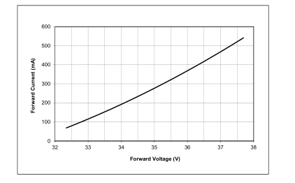
Figure 3: Vero 10D Drive Current vs. Voltage
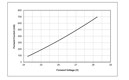
Figure 5: Vero 10C Typical Relative Flux vs. Current
Notes for Figures 1-6:
Figure 2: Vero 10C Drive Current vs. Voltage
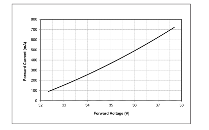
Figure 4: Vero 10B Typical Relative Flux vs. Current
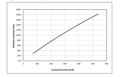
Figure 6 Vero 10D Typical Relative Flux vs. Current
- Bridgelux does not recommend driving high power LEDs at low currents. Doing so may produce unpredictable results. Pulse width modulation (PWM) is recommended for dimming effects. 2. Products tested under pulsed condition (10ms pulse width) at nominal test current where Tj (junction temperature) = Tc (case temperature) = 25°C.
Page 28

Figure 7: Typical DC Flux vs. Case Temperature
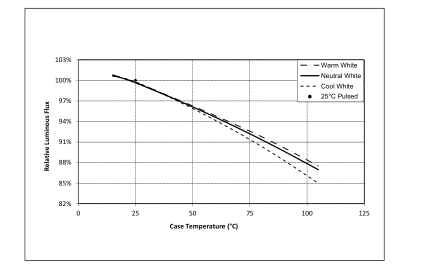
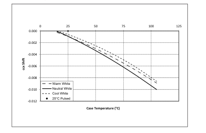
Figure 9: Typical DC ccx Shift vs. Case Temperature
Notes for Figures 7 - 9:
1. Characteristics shown for warm white based on 3000K and 80 CRI.
2. Characteristics shown for neutral white based on 4000K and 80 CRI.
3. Characteristics shown for cool white based on 5000K and 70 CRI.
Figure 8: Typical DC ccy Shift vs. Case Temperature
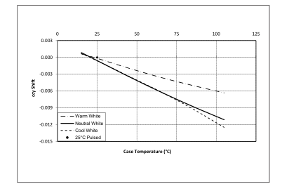
Figure 10: 2000K, 65 CRI Color Shift vs. Case Temperature
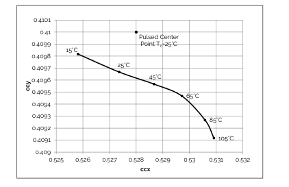
- For other color SKUs, the shift in color will vary. Please contact your Bridgelux Sales Representative for more information.
Page 29

Figure 11: 2700K, 97 CRI Color Shift vs. Case Temperature1
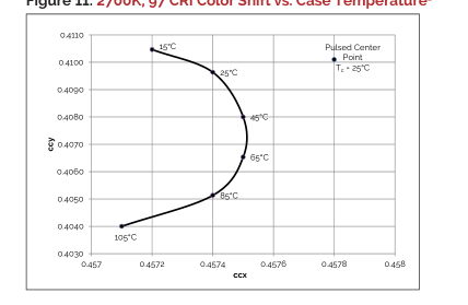
Figure 13: 3000K, 90 CRI Color Shift vs. Case Temperature3
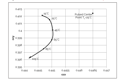
Figure 15: 3500K Class A Color Shift vs. Case Temperature1
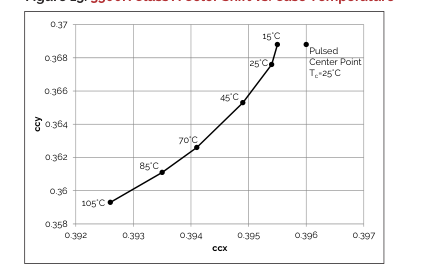
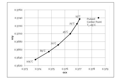
Notes for Figures 10-16: 1. Measurements made under DC test conditions at the nominal drive current. 2. Typical color shift is shown with a tolerance of ±0.002.
3. Characteristics shown for Decor Series Showcase products, BXRC-30G100C-x-73
Figure 12: 3000K, 97 CRI Color Shift vs. Case Temperature1
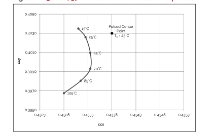
Figure 14: 3000K Class A Color Shift vs. Case Temperature1
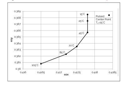
Figure 16: 4000K Class A Color Shift vs. Case Temperature1
Page 30

Figure 17: Typical Spatial Radiation Pattern
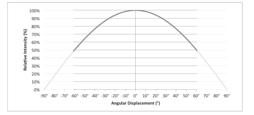
Notes for Figure 17: 1. Typical viewing angle is 120⁰. 2. The viewing angle is defined as the off axis angle from the centerline where intensity is ½ of the peak value.
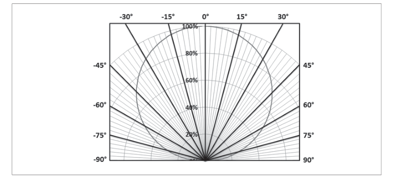
Figure 18: Typical Polar Radiation Pattern
Page 31

Figure 19: Typical Color Spectrum
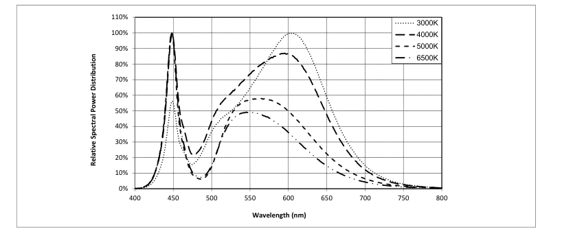
Notes for Figure 19: 1. Color spectra measured at nominal current for Tj = Tc = 25°C. 2. Color spectra shown is 3000K and 80 CRI. 3. Color spectra shown is 4000K and 80 CRI. 4. Color spectra shown is 5000K and 70 CRI. 4. Color spectra shown is 6500K and 70 CRI.
Figure 20: Typical Color Spectrum for Vero 10 with Décor Series
1
| 20B 27H | |
| 30G (Décor Series Showcase) 30H |
0.9
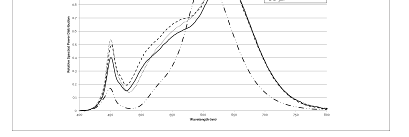
Note for Figure 20: 1. Color spectra measured at nominal current for Tj = Tc = 25°C.
Page 32

Figure 21: Drawing for Vero 10 LED Array
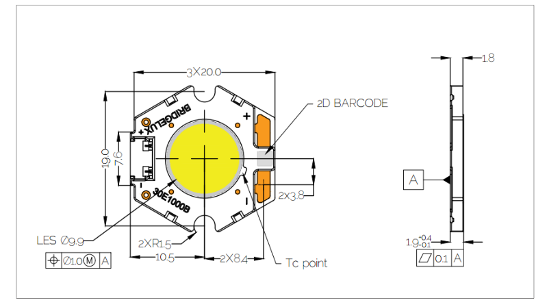
Notes for Figure 21: 1. Drawings are not to scale. 2. Dimensions are in mm. 3. Unless otherwise specified, tolerances are ± 0.10mm. 4. Mounting slots (2X) are for M2.5 screws. 5. Bridgelux recommends two tapped holes for mounting screws with 19.0 ± 0.10mm center-to-center spacing. 6. Screws with flat shoulders (pan, dome, button, round, truss, mushroom) provide optimal torque control. Do NOT use flat, countersink, or raised head screws. 7. Solder pads and connector port are labeled “+” and “-“ to denote positive and negative, respectively. 8. It is not necessary to provide electrical connections to both the solder pads and the connector port. Either set may be used depending
on application specific design requirements. 9. Refer to Application Notes AN30 and AN31 for product handling, mounting and heat sink recommendations. 10. The optical center of the LED Array is nominally defined by the mechanical center of the array to a tolerance of ± 0.2mm. 11. Bridgelux maintains a flatness of 0.10mm across the mounting surface of the array.
Page 33

Figure 22: Warm and Neutral White Test Bins in xy Color Space
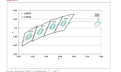
Note: Pulsed Test Conditions, Tc = 25°C
Figure 23: Graph of Cool White Test Bins in xy Color Space
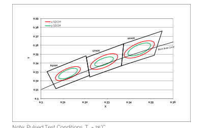
Note: Pulsed Test Conditions, Tc = 25°C
Table 9: Warm and Neutral White xy Bin Coordinates and Associated Typical CCT
| Bin Code | 2000K | 2700K | 3000K1 | 3500K1 | 4000K1 |
| ANSI Bin (for reference only) | - | (2580K - 2870K) | (2870K - 3220K) | (3220K - 3710K) | (3710K - 4260K) |
| 73 (3 SDCM) | - | (2651K - 2794K) | (2968K - 3136K) | (3369K - 3586K) | (3851K - 4130K) |
| 72 (2 SDCM) | - | (2674K - 2769K) | (2995K - 3107K) | (3404K - 3548K) | (3895K - 4081K) |
| Center Point (x,y) | (0.5280, 0.4100) | (0.4578, 0.4101) | (0.4338, 0.403) (0.4465, 0.4024)2 | (0.4073, 0.3917) | (0.3818, 0.3797) |
Notes for Table 9: 1. Color Binning information excludes Decor Series Class A products. Please contact your Bridgelux Sales Representative for more information. 2. Center Point for Decor Series Showcase. 3. Bridgelux maintains a tolerance of +/- 0.007 on x and y color coordinates in the CIE 1931 color Space.
Table 10: Cool White xy Bin Coordinates and Associated Typical CCT (product is hot targeted to Tc = 85°C)
| Bin Code | 5000K | 5700K | 6500K |
| ANSI Bin (for reference only) | (4745K - 5311K) | (5312K - 6022K) | (6022K - 7042K) |
| 74 (4 SDCM) | (4801K - 5282K) | (5395K- 5970K) | (6200K - 6910K) |
| 73 (3 SDCM) | (4835K-5215K) | (5460K- 5891K) | (6279K -6811K) |
| Center Point (x,y) | (0.3447, 0.3553) | (0.3287, 0.3417) | (0.3123, 0.3282) |
Note for Tables 10: 1. Bridgelux maintains a tolerance of +/- 0.007 on x and y color coordinates in the CIE 1931 color Space.
Page 34

Figure 24: Drawing for Vero 10 Packaging Tray
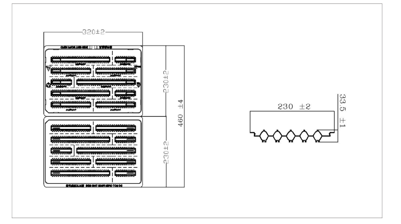
Notes for Figure 24: 1. Dimensions are in millimeters. 2. Drawings are not to scale.
Page 35

Figure 25: Vero Series Packaging and Labeling
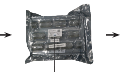
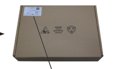
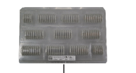
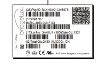
Notes for Figure 25: 1. Each tray holds 200 COBs. 2. Each tray is vacuum sealed in an anti-static bag and placed in its own box. 3. Each tray, bag and box is to be labeled as shown above.
Figure 26: Gen. 7 Product Labeling
Bridgelux COB arrays have laser markings on the back side of the substrate to help with product identification. In
addition to the product identification markings, Bridgelux COB arrays also contain markings for internal Bridgelux
manufacturing use only. The image below shows which markings are for customer use and which ones are for
Bridgelux internal use only. The Bridgelux internal manufacturing markings are subject to change without notice,
however these will not impact the form, function or performance of the COB array.

Customer Use- 2D Barcode Scannable barcode provides product part number and other Bridgelux internal production information.
Customer Use- Vf Bin Code
30E1000C 73 2F
Customer Use- Product part number
included to enable greater luminaire design flexibility. Refer to AN92 for bin code definitions.
Page 36

Application Notes
Bridgelux has developed a comprehensive set of application notes and design resources to assist customers in successfully designing with the Vero product family of LED array products. For all available application notes visit www.bridgelux.com.
Optical Source Models
Optical source models and ray set files are available for all Bridgelux products. For a list of available formats, visit www.bridgelux.com.
Precautions
CAUTION: CHEMICAL EXPOSURE HAZARD
Exposure to some chemicals commonly used in luminaire manufacturing and assembly can cause damage to the LED array. Please consult Bridgelux Application Note AN31 for additional information.
CAUTION: RISK OF BURN
Do not touch the Vero LED array during operation. Allow the array to cool for a sufficient period of time before handling. The Vero LED array may reach elevated temperatures such that could burn skin when touched.
Disclaimers
MINOR PRODUCT CHANGE POLICY
The rigorous qualification testing on products offered by Bridgelux provides performance assurance. Slight cosmetic changes that do not affect form, fit, or function may occur as Bridgelux continues product optimization.
3D CAD Models
Three dimensional CAD models depicting the product outline of all Bridgelux Vero LED arrays are available in both IGS and STEP formats. Please contact your Bridgelux sales representative for assistance.
LM80
LM80 testing has been completed and the LM80 report is now available. Please contact your Bridgelux sales rep resentative for LM-80 report.
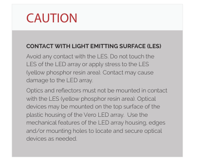
STANDARD TEST CONDITIONS
Unless otherwise stated, array testing is performed at the nominal drive current.
Page 37

At Bridgelux, we help companies, industries and people experience the power and possibility of light. Since 2002, we’ve designed LED solutions that are high performing, energy efficient, cost effective and easy to integrate. Our focus is on light’s impact on human behavior, delivering products that create better environments, experiences and returns—both experiential and financial. And our patented technology drives new platforms for commercial and industrial luminaires.
For more information about the company, please visit
bridgelux.com
twitter.com/Bridgelux
facebook.com/Bridgelux
youtube.com/user/Bridgelux
linkedin.com/company/bridgelux-inc-_2
WeChat ID: BridgeluxInChina
46410 Fremont Boulevard Fremont, CA 94538 U.S.A. Tel (925) 583-8400 www.bridgelux.com
© 2023 Bridgelux, Inc. All rights reserved. Product specifications are subject to change without notice. Bridgelux, the Bridgelux stylized logo design, Vero, V Series and V Series HD are registered trademarks, and Decor Series is a trademark of Bridgelux, Inc. All other trademarks are the property of their respective owners.
Bridgelux Gen 7 Vero 10 Array Series Product Data Sheet DS90 Rev. S (08/2023)