


 Download PDF
DS584 BRIDGELUX
Document overview
- PDF pages: 13
Technical content
Page 1
Page 2

Bridgelux Vesta Series Thrive 97 Triple CCT EB are fully engineered devices that provide consistent thermal and optical performance on an engineered mechanical platform. The linear EB products incorporate several features to simplify design integration and assembly. Please visit www.bridgelux.com for more information on the Vesta Series family of products.
Re-usable connector

Designed to comply with global safety standards
Label containing part number and lot codes is
for creepage and clearance distances
attached on the front of the module where shown
Product Nomenclature
The part number designation for Bridgelux Vesta Series EB is explained as follows:
1 2 3 4 5 678 9 10111213 14 15 16 17 18 192021 22 23
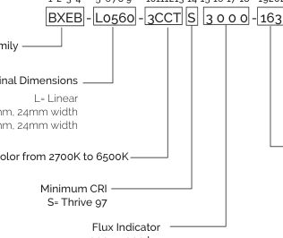
Product Family
0560 = 560mm, 24mm width 1120 = 1120mm, 24mm width
3CCT = white color from 2700K to 6500K
3000 = 3000 lm 6000 = 6000 lm
CCT Bin Options 3 = 3 SDCM
EB Version A = Gen1
EB Configuration 16= 16 in series 3 = 3 in parallel 6 = 6 in parallel
Page 3

The following product configurations are available:
Table 1: Selection Guide, White Pulsed Measurement Data (Tj=Tc=25°C)
| Part Number | Nominal CCT1 (K) | CRI2 | Nominal If Total (mA) | Nominal Drive Current Per Channel (mA) | Forward Voltage3 (V) | Typical Power (W) | Typical Pulsed Flux3, 4, 5 (lm) | Typical Efficacy (lm/W) | |||
|---|---|---|---|---|---|---|---|---|---|---|---|
| C1 | C2 | C3 | C3 | ||||||||
| BXEB-L0560-3CCTS 3000-163-A3 | 2700 | 97 | 450 | 212 | 212 | 13 | 13 | 46 | 21 | 2435 | 116 |
| 3000 | 161 | 235 | 27 | 27 | 46 | 21 | 2529 | 121 | |||
| 3500 | 118 | 239 | 46 | 46 | 46 | 21 | 2616 | 126 | |||
| 4000 | 79 | 231 | 70 | 70 | 46 | 21 | 2696 | 130 | |||
| 5000 | 49 | 173 | 114 | 114 | 46 | 21 | 2778 | 136 | |||
| 5700 | 49 | 123 | 139 | 139 | 45 | 20 | 2792 | 137 | |||
| 6500 | 51 | 68 | 166 | 166 | 46 | 21 | 2791 | 136 | |||
| BXEB-L1120-3CCTS 6000-166-A3 | 2700 | 97 | 900 | 425 | 425 | 25 | 25 | 46 | 42 | 4870 | 116 |
| 3000 | 322 | 470 | 54 | 54 | 46 | 42 | 5058 | 121 | |||
| 3500 | 236 | 479 | 93 | 93 | 46 | 41 | 5232 | 126 | |||
| 4000 | 158 | 462 | 140 | 140 | 46 | 41 | 5391 | 130 | |||
| 5000 | 98 | 345 | 228 | 228 | 46 | 41 | 5556 | 136 | |||
| 5700 | 98 | 247 | 277 | 277 | 45 | 41 | 5585 | 137 | |||
| 6500 | 102 | 135 | 332 | 332 | 46 | 41 | 5582 | 136 | |||
Notes for Table 1: 1. Nominal CCT as defined by ANSI C78.377-2011. 2. Listed CRIs are minimum values and include test tolerance. 3. Products tested under pulsed condition (10ms pulse width) at nominal drive current where Tj (junction temperature) = Tc (case temperature) = 25°C. 4. Typical performance values are provided as a reference only and are not a guarantee of performance. 5. Bridgelux maintains a ±7.5% tolerance on flux measurements 6. C1, C2, and C3 refer to the three different CCTs (chips) used in the Triple CCT SMD3838.
Page 4

The following product configurations are available:
Table 2: Selection Guide, Triple CCT Pulsed Measurement Data (Tj=Tc=25°C)
| Part Number | Color | Nominal Drive Current (mA) | Forward Voltage3 (V) | Typical Power (W) | Typical Pulsed Flux3,4 (lm) | Typical Efficacy (lm/W) | ||
|---|---|---|---|---|---|---|---|---|
| Min | Typical | Max | ||||||
| BXEB-L0560-3CCTS3000-163-A3 | C1 | 180 | 44.5 | 46.7 | 53 | 8.4 | 827 | 98 |
| C2 | 180 | 44.5 | 46.7 | 53 | 8.4 | 1087 | 129 | |
| C3 | 180 | 44.5 | 46.7 | 53 | 8.4 | 1143 | 136 | |
| BXEB-L1120-3CCTS6000-166-A3 | C1 | 360 | 44.5 | 46.7 | 53 | 16.8 | 1654 | 98 |
| C2 | 360 | 44.5 | 46.7 | 53 | 16.8 | 2174 | 129 | |
| C3 | 360 | 44.5 | 46.7 | 53 | 16.8 | 2286 | 136 | |
Notes for Table 2: 1. C1, C2, and C3 refer to the three different CCTs (chips) used in the Triple CCT SMD3838. 2. Products tested under pulsed condition (10ms pulse width) at nominal drive current where Tj (junction temperature) = Tc (case temperature) = 25°C. 3. Typical performance values are provided as a reference only and are not a guarantee of performance. 4. Bridgelux maintains a ±7.5% tolerance on flux measurements
Page 5

Table 3: Maximum Ratings
| Parameter | Maximum Rating | |||||
|---|---|---|---|---|---|---|
| Storage Temperature | -40°C to +85°C | |||||
| Operating Case Temperature (T) c | 85°C | |||||
| Soldering Temperature | 350°C or lower for a maximum of 5 seconds | |||||
| BXEB-L0560-3CCTS3000-163-A3 | BXEB-L1120-3CCTS6000-166-A3 | |||||
| C1 | C2 | C3 | C1 | C2 | C3 | |
| Maximum Drive Current Per Color | 480mA | 480mA | 480mA | 960mA | 960mA | 960mA |
Table 4: Tunable White Ratio
| CCT Color | 2700K | 3000K | 3500K | 4000K | 5000K | 5700K | 6500K |
| C1 | 47.17% | 35.82% | 26.22% | 17.58% | 10.90% | 10.90% | 11.28% |
| C2 | 47.17% | 52.24% | 53.18% | 51.37% | 38.35% | 27.44% | 15.04% |
| C3 | 2.83% | 5.97% | 10.30% | 15.53% | 25.38% | 30.83% | 36.84% |
| C3 | 2.83% | 5.97% | 10.30% | 15.53% | 25.38% | 30.83% | 36.84% |
Page 6

Figure 1: Relative Current Ratio vs. CCT at CRI 97 (Tc= 25°C)
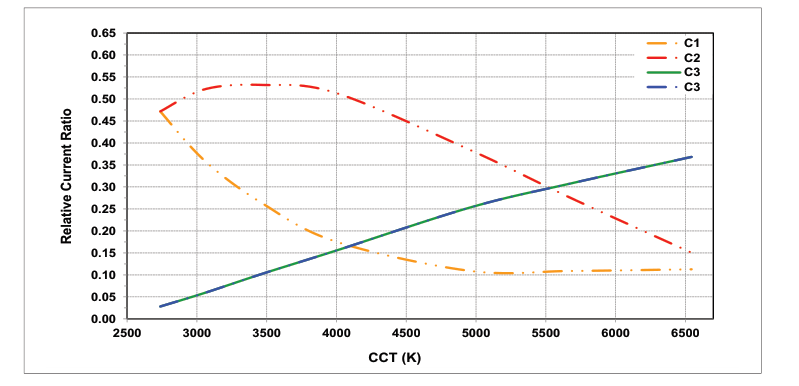
Figure 2: Typical Color Spectrum (White CCT, at Tc = 55°C)
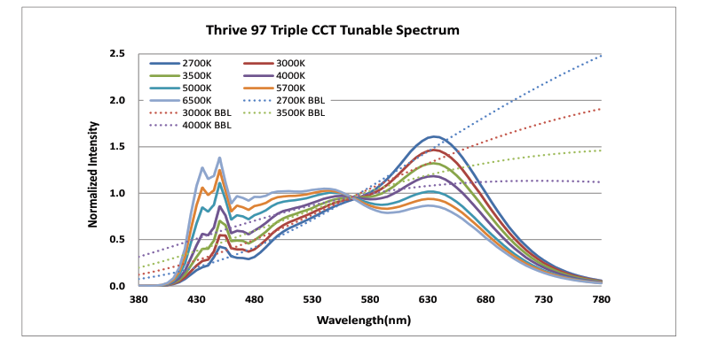
Note for Figure 2: 1. Color spectra measured at nominal current for Tc = 55°C.
Page 7

Figure 3: Typical Relative Luminous Flux vs. Solder Point Temperature
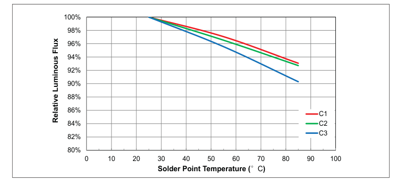
Figure 4: Typical Color Spectrum
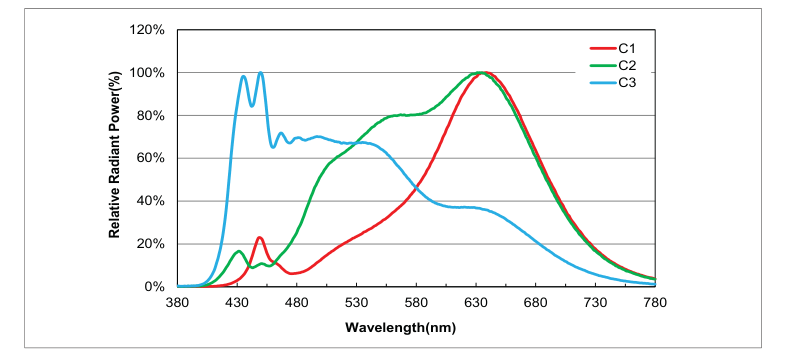
Note for Figure 4: 1. Color spectra measured at nominal current for Tc = 25°C.
Page 8

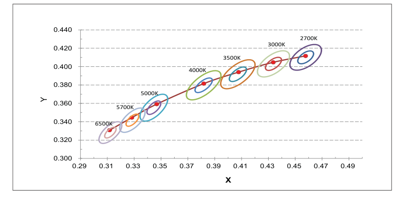
Figure 5: Chromaticity Coordinate Group (Color Targeted at Tc= 55°C)
Page 9

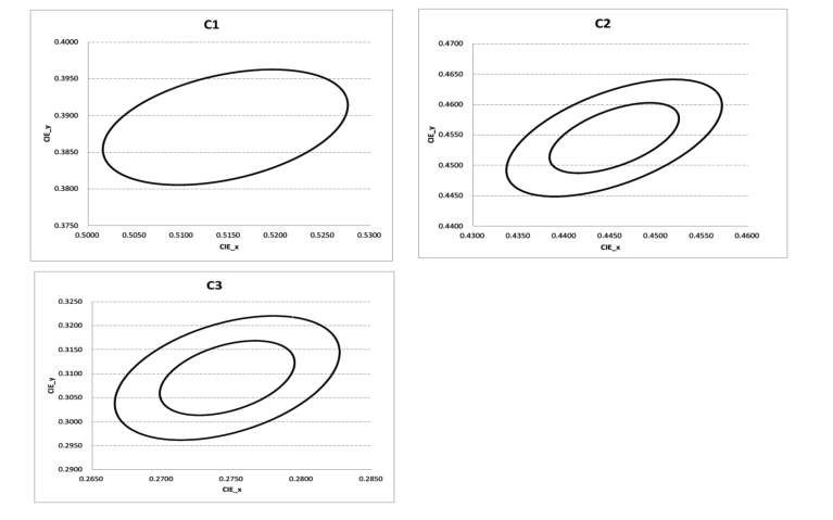
Table 5: MacAdam Ellipse Color Bin Definitions
| Color | Color Space | Center Point | Major Axis | Minor Axis | Ellipse Rotation Angle | Color Bin | |
|---|---|---|---|---|---|---|---|
| X | Y | ||||||
| C1 | 5 SDCM | 0.5146 | 0.3884 | 0.0135 | 0.0070 | 53.70 | 5 |
| C2 | 3 SDCM | 0.4454 | 0.4545 | 0.0081 | 0.0042 | 35 | 3 |
| 6 SDCM | 0.4454 | 0.4545 | 0.0162 | 0.0084 | 35 | 6 | |
| C3 | 3 SDCM | 0.2747 | 0.3091 | 0.0162 | 0.0084 | 70 | 3 |
| 6 SDCM | 0.2747 | 0.3091 | 0.0162 | 0.0084 | 70 | 6 | |
Notes for Table 5: 1. Color binning at Tc= 25°C unless otherwise specified 2. Bridgelux maintains a tolerance of ± 0.007 on x and y color coordinates.
Figure 6: Chromaticity Coordinate Group (Color Targeted at Tc=25°C)
Page 10

Figure 7: Drawing Overview for 560mm EB
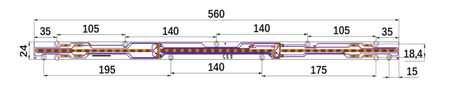
Figure 8: Drawing Overview for 1120mm EB

Notes for Figures 7 & 8: 1. Connectors are labeled “+” to denote positive polarity, and “-” to denote negative polarity. 2. Drawing dimensions are in millimeters.
Table 6: Module Dimensions & Connector Wiring
| Parameter | BXEB-L0560-3CCTS3000-163-A3 | BXEB-L1120-3CCTS6000-166-A3 |
|---|---|---|
| Linear length | 560 mm | 1120 mm |
| Linear width | 24 mm | 24 mm |
| Overall thickness | 6.1 mm | |
| PCB thickness | 1.6 mm | |
| Input wire cross-section | 18-24 AWG | |
| Wire strip length | 7-9 mm | |
Page 11

Figure 9: EB Series Packaging and Labeling
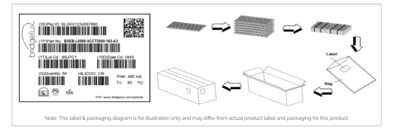
Table 7: Packaging Structure
| Box Parameter | L0560 modules | L1120 modules |
|---|---|---|
| Quantity | 100 | 100 |
| Dimension | 65.0 cm x 19.4 cm x 16.9 cm | 120.8 cm x 19.4 cm x 16.9 cm |
Figure 10: Product Labeling
Bridgelux Vesta Series Thrive 97 Triple CCT EB modules contain a label on the front to help with product identification. In addition to the product identification markings, Bridgelux Vesta Series Triple CCT EB modules also contain markings for internal Bridgelux manufacturing use only. The image below shows which markings are for customer use and which ones are for Bridgelux internal use only. The Bridgelux internal manufacturing markings are subject to change without notice, however these will not impact the form, function or performance of the module.
Customer Use- 2D Barcode
Vesta Series Thrive
Scannable barcode provides
Triple CCT EB
product part number and other Bridgelux internal production
4ft 3000lm 480mA
information.
Page 12

Application Notes
Vesta Series Triple CCT EB are intended for use in dry, indoor applications. Bridgelux has developed a comprehensive set of application notes and design resources to assist customers in successfully designing with the Vesta Series product family of Triple CCT EB products. For a list of resources under development, visit www.bridgelux.com.
Optical Source Models
Optical source models and ray set files are available for all Bridgelux products. For a list of available formats, visit www.bridgelux.com.
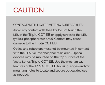
Precautions
CAUTION: CHEMICAL EXPOSURE HAZARD
Exposure to some chemicals commonly used in luminaire manufacturing and assembly can cause damage to the Triple CCT EB. Please consult Bridgelux Application Note for additional information.
CAUTION: EYE SAFETY
The Bridgelux Vesta series Triple CCT EB emits visible light, that, under certain circumstances, could be harmful to the eye. Proper safeguards must be used.
CAUTION: RISK OF BURN
Do not touch the Vesta Series Triple CCT EB during operation. Allow the Triple CCT EB to cool for a sufficient period of time before handling. The Vesta Series Triple CCT EB may reach elevated temperatures such that could burn skin when touched.
Disclaimers
STANDARD TEST CONDITIONS
Unless otherwise stated, Triple CCT EB testing is performed at the nominal drive current.
3D CAD Models
Three dimensional CAD models depicting the product outline of all Bridgelux Vesta Series Triple CCT EB are available in both IGS and STEP formats. Please contact your Bridgelux sales representative for assistance.
LM80
Please contact your Bridgelux sales representative for more information.
MINOR PRODUCT CHANGE POLICY
The rigorous qualification testing on products offered by Bridgelux provides performance assurance. Slight cosmetic changes that do not affect form, fit, or function may occur as Bridgelux continues product optimization.
Page 13

At Bridgelux, we help companies, industries and people experience the power and possibility of light. Since 2002, we’ve designed LED solutions that are high performing, energy efficient, cost effective and easy to integrate. Our focus is on light’s impact on human behavior, delivering products that create better environments, experiences and returns—both experiential and financial. And our patented technology drives new platforms for commercial and industrial luminaires.
For more information about the company, please visit
bridgelux.com
twitter.com/Bridgelux
facebook.com/Bridgelux
youtube.com/user/Bridgelux
linkedin.com/company/bridgelux
WeChat ID: BridgeluxInChina
46410 Fremont Blvd Fremont, CA 94538 USA Tel (925) 583-8400 www.bridgelux.com
© 2024 Bridgelux, Inc. All rights reserved 2023. Product specifications are subject to change without notice. Bridgelux, the Bridgelux stylized logo design and Vesta are registered trademarks of Bridgelux, Inc. All other trademarks are the property of their respective owners.
Bridgelux Vesta Series Thrive Triple CCT EB with SMD3838 Product Data Sheet DS584 Rev. A (11/2024)