

 Download PDF
DS02-254_V01 CUI
Document overview
- PDF pages: 3
Technical content
Page 1
date 11/23/2021 page 1 of 3
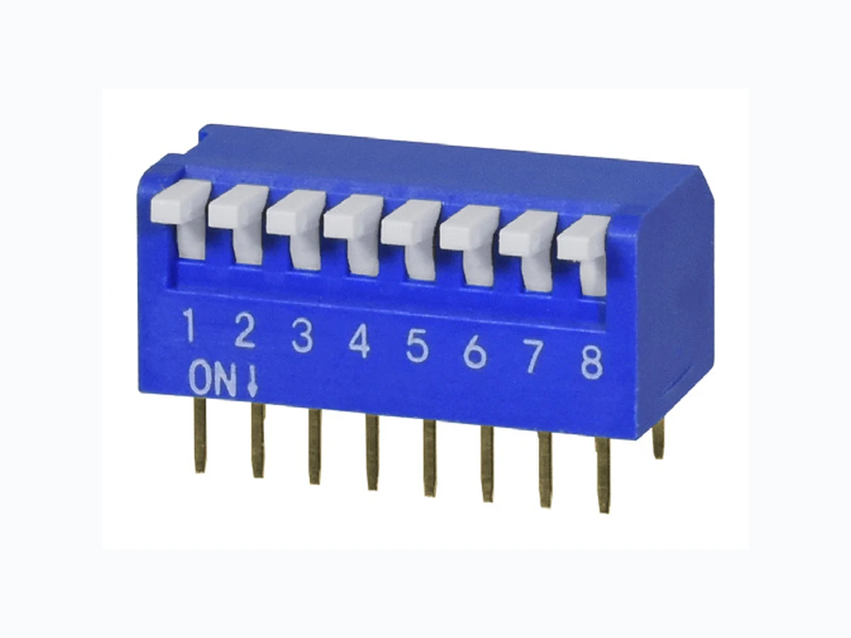
SERIES: DS02-254 │ DESCRIPTION: DIP SWITCH
FEATURES
- 2.54 mm pitch
- convex or flat bottom option
- 2~12 pole options
- raised or flat actuator option
- through hole
SPECIFICATIONS
parameter
conditions/description
min
typ
max
units
switching
24
Vdc
rated voltage (per pole)
non-switching
50
Vdc
switching
25
mA
rated current (per pole)
non-switching
100
mA
withstanding voltage
for 1 minute
300
Vac
initial
50
mΩ
contact resistance
after life test
100
mΩ
insulation resistance
at 500 Vdc
100
MΩ
operating force
1000
g
switch travel angle
20
°
operating temperature
-40
85
°C
storage temperature
-40
85
°C
life
2000
cycles
flammability rating
UL94V-0
RoHS
yes
SOLDERABILITY
parameter
conditions/description
min
typ
max
units
hand soldering1
for maximum 3 seconds
315
320
325
°C
wave soldering1
for maximum 5 seconds
240
250
260
°C
Notes: 1. Keep in “off” position during soldering.
PART NUMBER KEY
DS02 X - 254 - X L - XX BE
Base Number
Base:
Actuator:
No. of Poles:
“blank” = Flat
1 = Raised
02 07
C2 = Convex
2 = Flat
Notes: 2. Convex base only available in poles 3~12. \*. Discontinued DS02C-254-2L models
Page 2
CUI Devices │ SERIES: DS02-254 │ DESCRIPTION: DIP SWITCH
MECHANICAL DRAWING
units: mm
ITEM
tolerance:
1
0.5<X≤3.0: ±0.15 mm 3.0<X≤6.0: ±0.20 mm
2
6.0<X≤30.0: ±0.25 mm
3
30.0<X≤120.0: ±0.30 mm 120.0<X≤400.0: ±0.50 mm
4
X>400.0: ±0.80 mm
5
unless otherwise noted
date 11/23/2021│ page 2 of 3
DESCRIPTION
MATERIAL
PLATING/COLOR
housing
PBT (UL94V-0)
blue
actuator
PBT (UL94V-0)
white
base
PBT (UL94V-0)
black
pin 1
copper alloy
gold
pin 2
copper alloy
gold
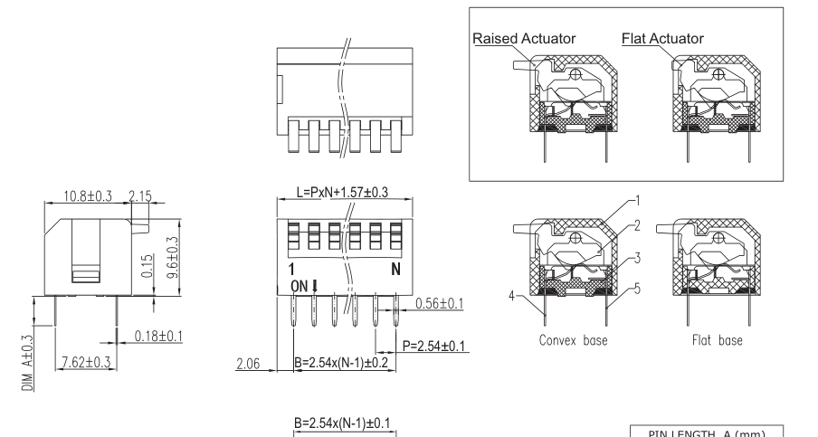

| PIN LENGTH, A (mm) | |
| Long Pin | |
| Flat Base | 3.80 |
| Convex Bas | e 3.65 |
Recommended PCB Layout
Top View
This series is constructed of single piece modules where L is the total length, P is the pitch, and N is
the number of poles.
| N | 02 | 03 | 04 | 05 | 06 | 07 | 08 | 10 |
| L | 6.65 | 9.19 | 11.73 | 14.27 | 16.81 | 19.35 | 21.89 | 26.97 |
| B | 2.54 | 5.08 | 7.62 | 10.16 | 12.70 | 15.24 | 17.78 | 22.86 |
12 32.05 27.94
Page 3
CUI Devices │ SERIES: DS02-254 │ DESCRIPTION: DIP SWITCH
date 11/23/2021│ page 3 of 3
REVISION HISTORY
| rev. | description | date |
|---|---|---|
| 1.0 | initial release | 11/21/2019 |
| 1.01 | discontinued DS02C-254-2L models | 11/23/2021 |
The revision history provided is for informational purposes only and is believed to be accurate.
CUI Devices offers a one (1) year limited warranty. Complete warranty information is listed on our website.
CUI Devices reserves the right to make changes to the product at any time without notice. Information provided by CUI Devices is believed to be accurate and reliable. However, no responsibility is assumed by CUI Devices for its use, nor for any infringements of patents or other rights of third parties which may result from its use.
CUI Devices products are not authorized or warranted for use as critical components in equipment that requires an extremely high level of reliability. A critical component is any component of a life support device or system whose failure to perform can be reasonably expected to cause the failure of the life support device or system, or to affect its safety or effectiveness.