Download PDF
DRV101 BURR-BROWN
Document overview
- PDF pages: 19
Technical content
Page 1
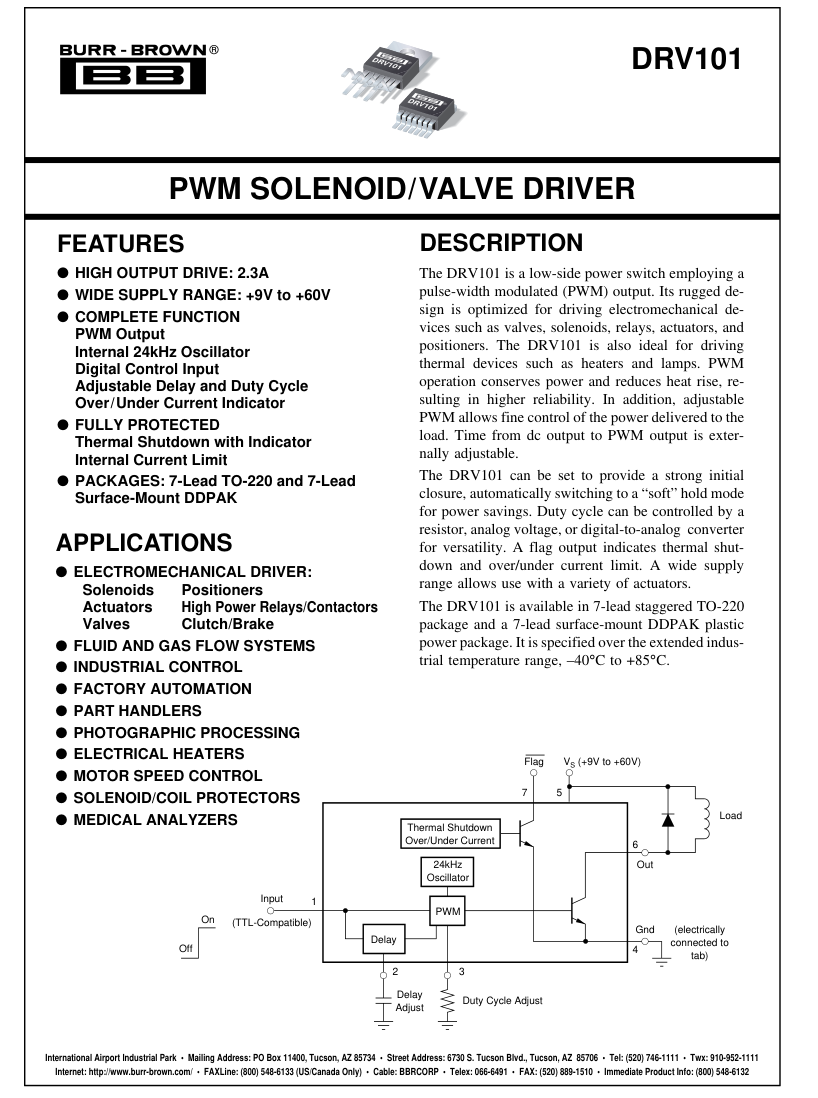
©1998 Burr-Brown Corporation
PDS-1411B
Printed in U.S.A. August, 1998
Page 2
SPECIFICATIONS
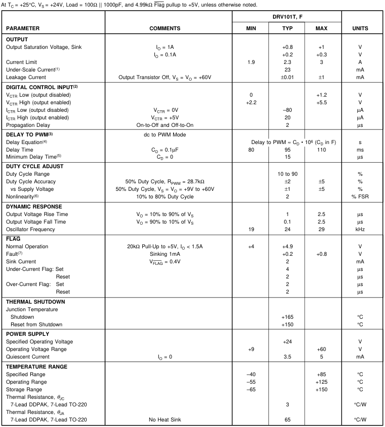
NOTES:(1) Under-scale current for TC < 100°C—see Under-Scale Current vs Temperature typical performance curve. (2) Logic High enables output (normal operation). (3) Constant dc output to PWM (pulse-width modulated) time. (4) Maximum delay is determined by an external capacitor. Pulling the Delay Adjust Pin low corresponds to an infinite (continuous) delay. (5) Connecting the Delay Adjust pin to +5V reduces delay time to 3µs. (6) VIN at pin 3 to percent of duty cycle at pin 6. (7) A fault results from over-temperature, over-current, or under-current conditions.
The information provided herein is believed to be reliable; however, BURR-BROWN assumes no responsibility for inaccuracies or omissions. BURR-BROWN assumes no responsibility for the use of this information, and all use of such information shall be entirely at the user’s own risk. Prices and specifications are subject to change without notice. No patent rights or licenses to any of the circuits described herein are implied or granted to any third party. BURR-BROWN does not authorize or warrant any BURR-BROWN product for use in life support devices and/or systems.
Page 3
CONNECTION DIAGRAMS
ABSOLUTE MAXIMUM RATINGS(1)
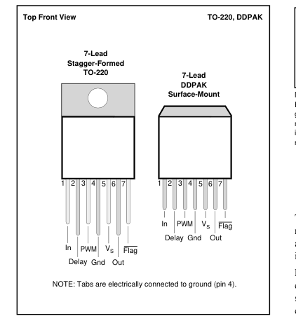
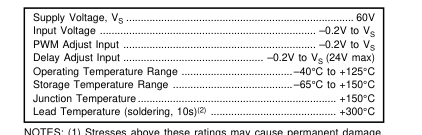
NOTES: (1) Stresses above these ratings may cause permanent damage. Exposure to absolute maximum conditions for extended periods may de- grade device reliability. (2) Vapor-phase or IR reflow techniques are recommended for soldering the DRV101F surface-mount package. Wave soldering is not recommended due to excessive thermal shock and “shadowing” of nearby devices.
ELECTROSTATIC
DISCHARGE SENSITIVITY
This integrated circuit can be damaged by ESD. Burr-Brown
recommends that all integrated circuits be handled with
appropriate precautions. Failure to observe proper handling and
installation procedures can cause damage. ESD damage can range from subtle performance degradation to
complete device failure. Precision integrated circuits may be more
susceptible to damage because very small parametric changes
could cause the device not to meet its published specifications.
PACKAGE/ORDERING INFORMATION
| PRODUCT | PACKAGE | PACKAGE DRAWING NUMBER(1) | SPECIFIED TEMPERATURE RANGE | PACKAGE MARKING | ORDERING NUMBER(2) | TRANSPORT MEDIA |
| DRV101T DRV101F " | 7-Lead Stagger-Formed TO-220 7-Lead DDPak Surface Mount " | 327 328 " | –40°C to +85°C –40°C to +85°C " | DRV101T DRV101F " | DRV101T DRV101F DRV101F/500 | Rails Rails Tape and Reel |
NOTES: (1) For detailed drawing and dimension table, please see end of data sheet, or Appendix C of Burr-Brown IC Data Book. (2) Models with a slash (/) are available only in Tape and Reel in the quantities indicated (e.g., /500 indicates 500 devices per reel). Ordering 500 pieces of “DRV101F/500” will get a single 500-piece Tape and Reel. For detailed Tape and Reel mechanical information, refer to Appendix B of Burr-Brown IC Data Book.
Page 4
PIN DESCRIPTIONS
| PIN # | NAME | DESCRIPTION |
|---|---|---|
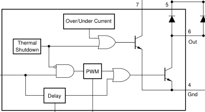
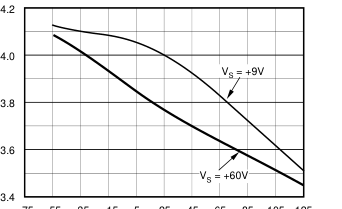
| Pin 1 | Input | The input is compatible with standard TTL levels. The device output becomes enabled when the input voltage is driven above the typical switching threshold, 1.7V. Below this level, the output is disabled. With no connection to the pin, the input level rises to 3.4V. Input current is 20µA when driven high and 80µA with the input low. The input may be momentarily driven to the power supply (V ) without damage. S |
| Pin 2 | Delay Adjust | This pin sets the duration of the initial 100% duty cycle before the output goes into PWM mode. Leaving this pin floating results in a delay of approximately 15µs, which is internally limited by parasitic capacitance. Minimum delay may be reduced to less than 3µs by tying the pin to 5V. This pin connects internally to a 3µA current source from V and to a 3V threshold comparator. S When the pin voltage is below 3V, the output device is 100% on. The PWM oscillator is not synchronized to the Input (pin 1), so the first pulse may be extended by any portion of the programmed duty cycle. |
| Pin 3 | Duty Cycle Adjust (PWM) | Internally, this pin connects to the input of a comparator and a 19kΩ resistor to ground. It is driven by a 200µA current source from V . The voltage at this node linearly sets the duty cycle. Duty cycle can be programmed with a resistor, analog voltage, S or output of a D/A converter. The active voltage range is from 0.75V to 3.7V to facilitate the use of single-supply control electronics. At 0.75V (or R = 3.5kΩ), duty cycle is near 90%. Swing to ground should be limited to no lower than 0.1V. PWM PWM frequency is a constant 24kHz. |
| Pin 4 | Ground | This pin is electrically connected to the package tab. It must be connected to system ground for the DRV101 to function. It carries the 3.5mA quiescent current plus the load current when the device is on. |
| Pin 5 | V S | This is the power supply pin. Operating range is +9V to +60V. |
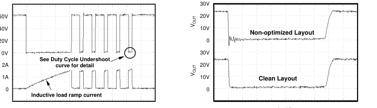
| Pin 6 | Out | The output is the collector of a power npn with the emitter connected to ground. Low power dissipation in the DRV101 is attained by the low saturation voltage and the fast switching transitions. Fall time is less than 75ns, rise time depends on load impedance. Base drive to the power device is limited with light loads to control turn-off delay. The response of this circuit causes the brief dip in saturation voltage after turn on. A flyback diode is needed with inductive loads to conduct the load current during the off cycle. The external diode should be selected for low forward voltage. The internal clamp diode provides protection but shouuld not be used to conduct load currents greater than 0.5A. |
| Pin 7 | Flag | Normally high (active low), the Flag signals either an over-temperature, over-current, or under-current fault. The over/under- current flags are true only when the output is on (constant dc output or the “on” portion of PWM mode). A thermal fault (thermal shutdown) occurs when the die surface reaches approximately 165°C and latches until the die cools to 150°C. Its output requires a pull-up resistor. It can typically sink two milliamps, sufficient to drive a low-current LED. |
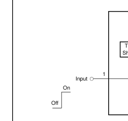
LOGIC BLOCK DIAGRAM


Page 5
TYPICAL PERFORMANCE CURVES
At TC = +25°C and VS = +24V, unless otherwise noted.
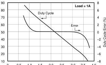
DUTY CYCLE and DUTY CYCLE ERROR vs VOLTAGE
0 0.5 1.0 1.5 2.0 2.5
3.0 3.5 4.0
VPWM (V)
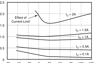
OUTPUT SATURATION VOLTAGE vs TEMPERATURE
–75 –50 –25
0 25 50 75 100 125
Temperature (°C)
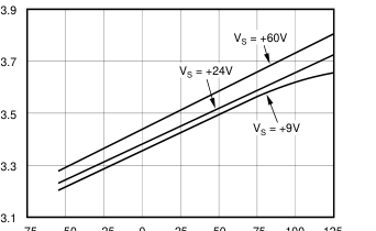
QUIESCENT CURRENT vs TEMPERATURE
–75 –50 –25
0 25 50 75 100 125
Temperature (°C)
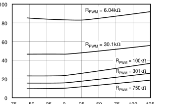
DUTY CYCLE vs TEMPERATURE
–75 –50 –25
0 25 50 75 100 125
Temperature (°C)
CURRENT LIMIT vs TEMPERATURE
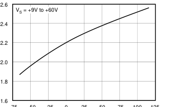
–75 –50 –25
0 25 50 75 100 125
Temperature (°C)
UNDER-SCALE CURRENT vs TEMPERATURE
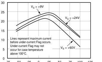
–75 –50 –25
0 25 50 75 100 125
Temperature (°C)
Page 6
TYPICAL PERFORMANCE CURVES (CONT)
At TC = +25°C and VS = +24V, unless otherwise noted.
FLAG OPERATION
FLAG OPERATION
OVER-CURRENT LIMIT
UNDER-CURRENT
(VS = +60V, CD = 110pF, RPWM = 750kΩ)
(VS = +24V, CD = 110pF, RPWM = 6.04kΩ)
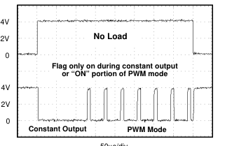
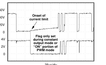
50µs/div
25µs/div
DC TO PWM MODE DRIVING INDUCTIVE LOAD
DUTY CYCLE UNDERSHOOT
(VS = +60V, CD = 110pF, RPWM = 301kΩ)
Load = 1A
1µs/div
50µs/div
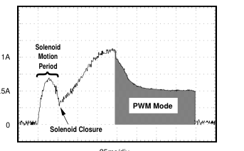
TYPICAL SOLENOID CURRENT WAVEFORM
(VS = +24V)
OSCILLATOR FREQUENCY vs TEMPERATURE
–75 –55 –35
–15 5 25 45 65 85 105 125
25ms/div
Temperature (°C)
Page 7
TYPICAL PERFORMANCE CURVES (CONT)
At TC = +25°C and VS = +24V, unless otherwise noted.
MINIMUM DELAY TO PWM vs TEMPERATURE
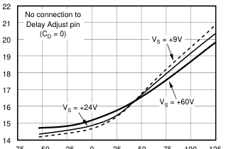
–75 –50 –25
0 25 50 75 100 125
Temperature (°C)
NOMINAL DELAY TIME TO PWM vs TEMPERATURE
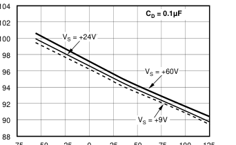
–75 –50 –25
0 25 50 75 100 125
Temperature (°C)
Page 8
BASIC OPERATION
The DRV101 is a low-side, bipolar power switch employing a pulse-width modulated (PWM) output for driving electromechanical and thermal devices. Its design is optimized for two types of applications; a two-state driver (open/close) for loads such as solenoids and actuators, and a linear driver for valves, positioners, heaters, and lamps. Its wide supply range, adjustable delay to PWM mode, and adjustable duty cycle make it suitable for a wide range of applications. Figure 1 shows the basic circuit connections to operate the DRV101. A 0.1µF bypass capacitor is shown connected to the power supply pin. The Input (pin 1) is compatible with standard TTL levels.
Input voltages between +2.2V and +5.5V turn the device output on, while pulling the pin low (0V to +1.2V), shuts the DRV101 output off. Input current is typically 80µA. Delay Adjust (pin 2) and Duty Cycle Adjust (pin 3) allow external adjustment of the PWM output signal. The Delay Adjust pin can be left floating for minimum delay to PWM mode (typically 15µs) or a capacitor can be used to set the delay time. Duty cycle of the PWM output can be controlled
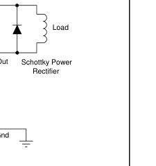
by a resistor, analog voltage, or D/A converter. Figure 1b provides an example timing diagram with the Delay Adjust pin connected to 0.1µF and duty cycle set for 25%. See the “Delay Adjust” and “Duty Cycle Adjust” text for equations and further explanation. Ground (pin 4) is electrically connected to the package tab. This pin must be connected to system ground for the DRV101 to function. This serves as the load current path to ground, as well as the DRV101 reference ground. The load (solenoid, valve, etc.) is connected between the supply (pin 5) and output (pin 6). For an inductive load, an external diode across the output is required as shown in Figure 1a. The diode serves to maintain the hold force during
PWM operation. For remotely located loads, the external diode should be placed close to the DRV101 (Figure 1a). The internal clamp diode between the output and ground should not be used to carry load current. The Flag (pin 7) provides fault status for under-current, over-current, and thermal shutdown conditions. This pin is active low with pin voltage typically +0.3V during a fault condition. A small value capacitor may be needed between Flag and ground for noisy applications.
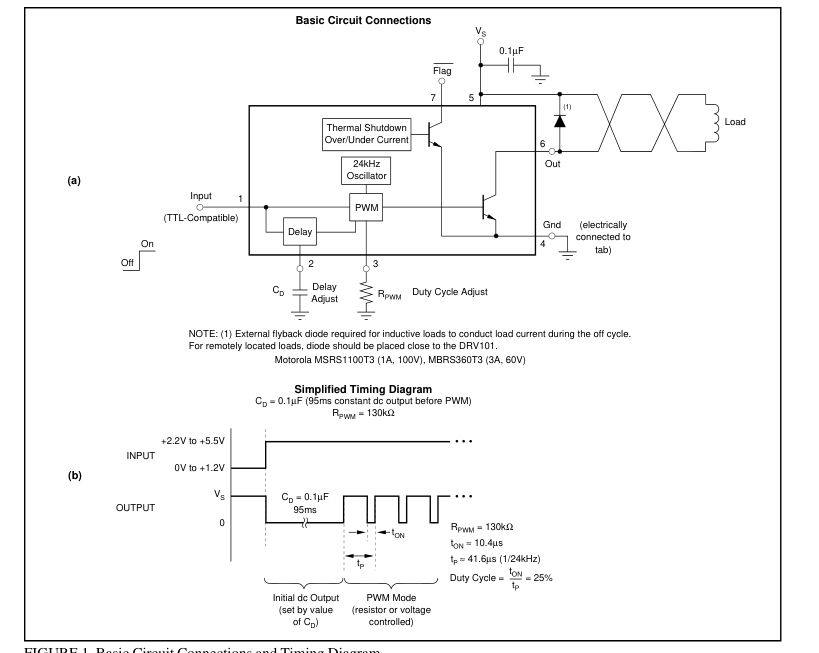
FIGURE 1. Basic Circuit Connections and Timing Diagram.
Page 9
APPLICATIONS INFORMATION
POWER SUPPLY
The DRV101 operates from a single +9V to +60V supply with excellent performance. Most behavior remains un- changed throughout the full operating voltage range. Parameters which vary significantly with operating voltage are shown in the Typical Performance Curves.
ADJUSTABLE INITIAL 100% DUTY CYCLE
A unique feature of the DRV101 is its ability to provide an initial constant dc output (100% duty cycle) and then switch to PWM mode to save power. This function is particularly useful when driving solenoids which have a much higher pull-in current requirement than hold requirement. The duration of this constant dc output (before PWM output begins) can be externally controlled with a capacitor connected from Delay Adjust (pin 2) to ground according to the following equation:
Delay Time ≈ CD • 106 (time in seconds, CD in Farads)
Leaving the Delay Adjust pin open results in a constant output time of approximately 15µs. The duration of this initial output can be reduced to less than 3µs by connecting the pin to 5V. Table I provides examples of desired “delay” times (constant output before PWM mode) and the appropriate capacitor values or pin connection.
| CONSTANT OUTPUT DURATION | C D |
| 3µs 15µs 100µs 1ms 100ms | Pin connected to 5V Pin open 100pF 1nF 0.1µF |
TABLE I. Delay Adjust Pin Connections.
The internal Delay Adjust circuitry is composed of a 3µA current source and a 3V comparator as shown in Figure 2. Thus, when the pin voltage is less than 3V, the output device is 100% on (dc output mode).
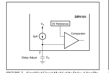
FIGURE 2. Simplified Circuit Model of the Delay Adjust Pin.
ADJUSTABLE DUTY CYCLE
The DRV101’s externally adjustable duty cycle provides an accurate means of controlling power delivered to the load. Duty cycle can be set from 10% to 100% with an external resistor, analog voltage, or the output of a D/A converter. Reduced duty cycle results in reduced power dissipation. This keeps the DRV101 and load cooler, resulting in in- creased reliability for both devices. PWM frequency is a constant 24kHz.
Resistor Controlled Duty Cycle Duty cycle is easily programmed with a resistor (RPWM) connected between the Duty Cycle Adjust pin and ground. Increased resistor values correspond to decreased duty cycles. Table II provides resistor values for typical duty cycles. Resistor values for additional duty cycles can be obtained from Figure 3. For reference purposes, the equation for calculating RPWM is included in Figure 3.
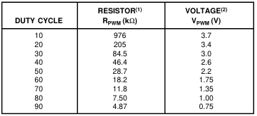
NOTES: (1) Resistor values listed are nearest 1% standard values. (2) Do not drive pin below 0.1V. For additional values, see “Duty Cycle vs Voltage” typical performance curve. TABLE II. Duty Cycle Adjust. TA= +25°C, VS = +24V.
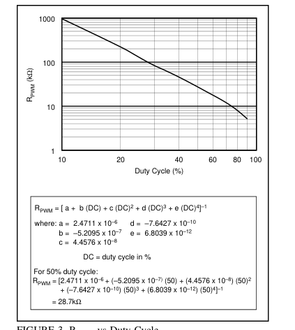
FIGURE 3. RPWM vs Duty Cycle.
Page 10
Voltage Controlled Duty Cycle Duty cycle can also be programmed with an analog voltage, VPWM. With VPWM ≈ 0.75V, duty cycle is near 90%. Increasing this voltage results in decreased duty cycles. Table II provides VPWM values for typical duty cycles. See the “Duty Cycle vs Voltage” Typical Performance Curve for additional duty cycles. The Duty Cycle Adjust pin should not be driven below 0.1V. If the voltage source used can go between 0.1V and ground, a series resistor between the voltage source and the Duty Cycle Adjust pin (Figure 4) is required to limit swing. If the pin is driven below 0.1V, the output will be unpredictable.
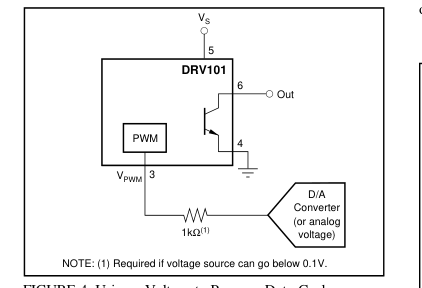
FIGURE 4. Using a Voltage to Program Duty Cycle.
The DRV101’s internal 24kHz oscillator sets the PWM period. This frequency is not externally adjustable. Duty Cycle Adjust (pin 3) is internally driven by a 200µA current source and connects to the input of a comparator and a 19kΩ resistor as shown in Figure 5. The DRV101’s PWM control design is inherently monotonic. That is, a decreased voltage (or resistor value) always produces an increased duty cycle.
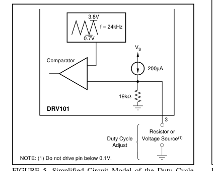
FIGURE 5. Simplified Circuit Model of the Duty Cycle
Adjust Pin.
STATUS FLAG
Flag (pin 7) provides fault indication for under-current, over-current, and thermal shutdown conditions. During a fault condition, Flag output is driven low (pin voltage typically drops to 0.3V). A pull-up resistor, as shown in Figure 6, is required to interface with standard logic. A small value capacitor may be needed between Flag and ground in noisy applications. Figure 6 gives an example of a non-latching fault monitoring circuit, while Figure 7 provides a latching version. The Flag pin can sink several milliamps, sufficent to drive external logic circuitry or an LED (Figure 8) to indicate when a fault has occurred. In addition, the Flag pin can be used to turn off
other DRV101’s in a system for chain fault protection.
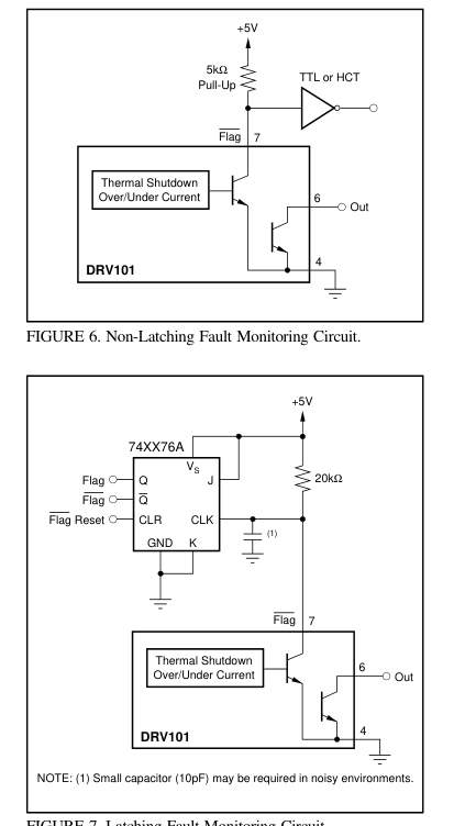
FIGURE 7. Latching Fault Monitoring Circuit.
Page 11
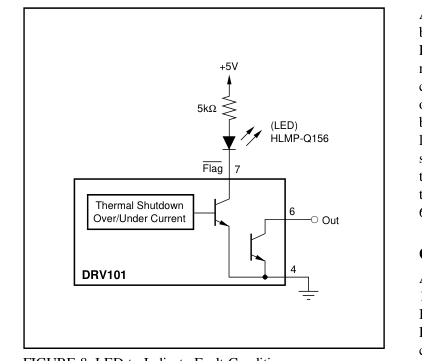
FIGURE 8. LED to Indicate Fault Condition.
Over/Under Current Fault An over-current fault occurs when the output current is greater than approximately 2.3A. The status flag is not latched. Since current during PWM mode is switched on and off, the flag output will be modulated with PWM timing (see flag waveforms in the Typical Performance Curves).
An under-current fault occurs when the output current is below the under-scale current threshold (typically 23mA). For example, this function indicates when the load is disconnected. Again, the flag output is not latched, so an undercurrent condition during PWM mode will produce a flag output that is modulated by the PWM waveform. An initial, brief under-current flag normally appears driving inductive loads and may be avoided by adding a parallel resistor sufficient to move the initial current above the under-current threshold. An under-current flag may not appear for case temperatures above 100°C. Avoid adding capacitance to pin 6 (Out) as it may cause momentary current limiting.
Over-Temperature Fault A thermal fault occurs when the die reaches approximately 165°C, producing a similar effect as pulling the input low. Internal shutdown circuitry disables the output and resets the Delay Adjust pin. The Flag is latched in the low state (fault condition) until the die has cooled to approximately 150°C. A thermal fault can occur in any mode of operation. Recovery from thermal fault will start in delay mode (constant dc output).
PACKAGE MOUNTING
Figure 9 provides recommended PCB layouts for both the TO-220 and DDPAK power packages. The tab of both packages is electrically connected to ground (pin 4). It may be desirable to isolate the tab of TO-220 package from its mounting surface with a mica (or other film) insulator (see
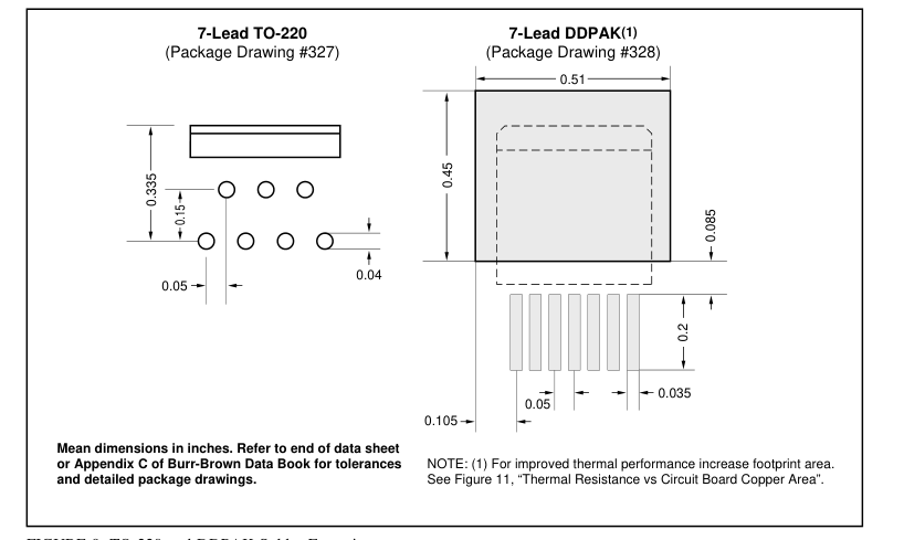
FIGURE 9. TO-220 and DDPAK Solder Footprints.
Page 12
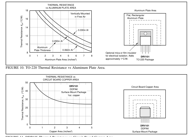
FIGURE 11. DDPAK Thermal Resistance vs Circuit Board Copper Area.
Figure 10). For lowest overall thermal resistance, it is best to isolate the entire heat sink/DRV101 structure from the mounting surface rather than to use an insulator between the semiconductor and heat sink. For best thermal performance, the tab of the DDPAK surface-mount version should be soldered directly to a circuit board copper area. Increasing the copper area improves heat dissipation. Figure 11 shows typical thermal resistance from junction-to-ambient as a function of the copper area.
POWER DISSIPATION
Power dissipation depends on power supply, signal, and load conditions. Power dissipation is equal to the product of output current times the voltage across the conducting output transistor times the duty cycle. Power dissipation can be minimized by using the lowest possible duty cycle necessary to assure the required hold force. Application Bulletin AB-039 explains how to calculate or measure power dissipation with unusual signals and loads.
THERMAL PROTECTION
Power dissipated in the DRV101 will cause the junction temperature to rise. The DRV101 has thermal shutdown circuitry that protects the device from damage. The thermal
protection circuitry disables the output when the junction temperature reaches approximately +165°C, allowing the device to cool. When the junction temperature cools to approximately +150°C, the output circuitry is again enabled. Depending on load and signal conditions, the thermal protection circuit may cycle on and off. This limits the dissipation of the amplifier but may have an undesirable effect on the load. Any tendency to activate the thermal protection circuit indicates excessive power dissipation or an inadequate heat sink. For reliable operation, junction temperature should be limited to +125°C, maximum. To estimate the margin of safety in a complete design (including heat sink), increase
the ambient temperature until the thermal protection is triggered. Use worst-case load and signal conditions. For good reliability, thermal protection should trigger more than 40°C above the maximum expected ambient condition of your application. This produces a junction temperature of 125°C at the maximum expected ambient condition. The internal protection circuitry of the DRV101 was de- signed to protect against overload conditions. It was not intended to replace proper heat sinking. Continuously running the DRV101 into thermal shutdown will degrade reliability.
Page 13
HEAT SINKING
Most applications will not require a heat sink to assure that the maximum operating junction temperature (125°C) is not exceeded. However, junction temperature should be kept as low as possible for increased reliability. Junction temperature can be determined according to the equation:
TJ = TA + PDθJA
(1)
where, θJA = θJC + θCH + θHA
(2)
TJ = Junction Temperature (°C) TA = Ambient Temperature (°C) PD = Power Dissipated (W) θJC = Junction-to-Case Thermal Resistance (°C/W) θCH = Case-to-Heat Sink Thermal Resistance (°C/W) θHA = Heat Sink-to-Ambient Thermal Resistance (°C/W) θJA = Junction-to-Air Thermal Resistance (°C/W) Figure 12 shows maximum power dissipation versus ambient temperature with and without the use of a heat sink. Using a heat sink significantly increases the maximum power dissipation at a given ambient temperature as shown.
MAXIMUM POWER DISSIPATION vs AMBIENT TEMPERATURE
10
| T | O-220 with Th 6030B Heat | P ermalloy Sink | = (T (max D J T (max) = J | ) – T )/θ A JA 125°C |
|---|---|---|---|---|
| θ JA = 16.7° | C/W | With infinit ( θ = 3 JA | e heat sink °C/W), | |
| DDPAK θ JA = 26°C/W | max P D at T = A | = 33W 25°C | ||
| (3 in2 one oz copper moun | ting pad) | |||
| DDPA θJA = 65°C | K or TO-220 /W (no heat si | nk) |
8
6
4
2
0 0 25 50 75 100 125
Ambient Temperature (°C)
FIGURE 12. Maximum Power Dissipation vs Ambient
Temperature.
The difficulty in selecting the heat sink required lies in determining the power dissipated by the DRV101. For dc output into a purely resistive load, power dissipation is simply the load current times the voltage developed across the conducting output transistor times the duty cycle. Other loads are not as simple. Consult Application Bulletin AB-039 for further insight on calculating power dissipation. Once power dissipation for an application is known, the proper heat sink can be selected.
Heat Sink Selection Example A TO-220 package is dissipating 5 Watts. The maximum expected ambient temperature is 35°C. Find the proper heat sink to keep the junction temperature below 125°C. Combining Equations 1 and 2 gives: TJ = TA + PD(θJC + θCH + θHA)
(3)
TJ, TA, and PD are given. θJC is provided in the specification table, 3°C/W. θCH can be obtained from the heat sink manufacturer. Its value depends on heat sink size, area, and material used. Semiconductor package type, mounting screw torque, insulating material used (if any), and thermal joint compound used (if any) also affect θCH. A typical θCH for a TO-220 mounted package is 1°C/W. Now we can solve for θHA:
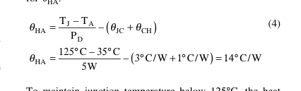
To maintain junction temperature below 125°C, the heat sink selected must have a θHA less than 14°C/W. In other words, the heat sink temperature rise above ambient must be less than 70°C (14°C/W x 5W). For example, at 5 Watts Thermalloy model number 6030B has a heat sink temperature rise of 66°C above ambient (θHA = 66°C/5W = 13.2°C/W), which is below the 70°C required in this ex- ample. Figure 12 shows power dissipation versus ambient temperature for a TO-220 package with a 6030B heat sink. Another variable to consider is natural convection versus forced convection air flow. Forced-air cooling by a small fan can lower θCA (θCH + θHA) dramatically. Heat sink manufac-
turers provide thermal data for both of these cases. For additional information on determining heat sink requirements, consult Application Bulletin AB-038. As mentioned earlier, once a heat sink has been selected, the complete design should be tested under worst-case load and signal conditions to ensure proper thermal protection.
Page 14
APPLICATION CIRCUITS
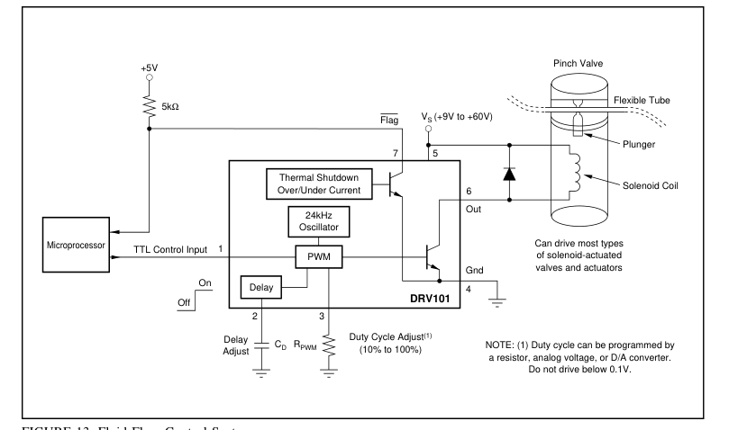
FIGURE 13. Fluid Flow Control System.
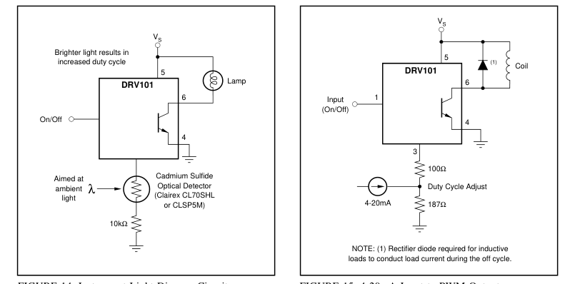
FIGURE 15. 4-20mA Input to PWM Output.
FIGURE 14. Instrument Light Dimmer Circuit.
Page 15
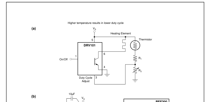
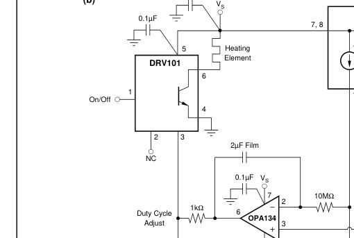
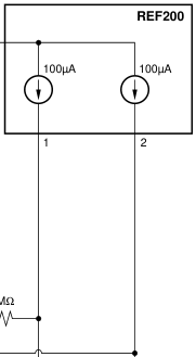
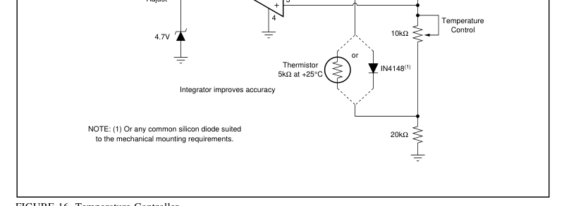
FIGURE 16. Temperature Controller.
Page 16
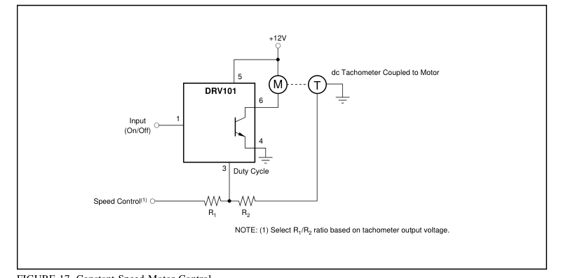
FIGURE 17. Constant Speed Motor Control.
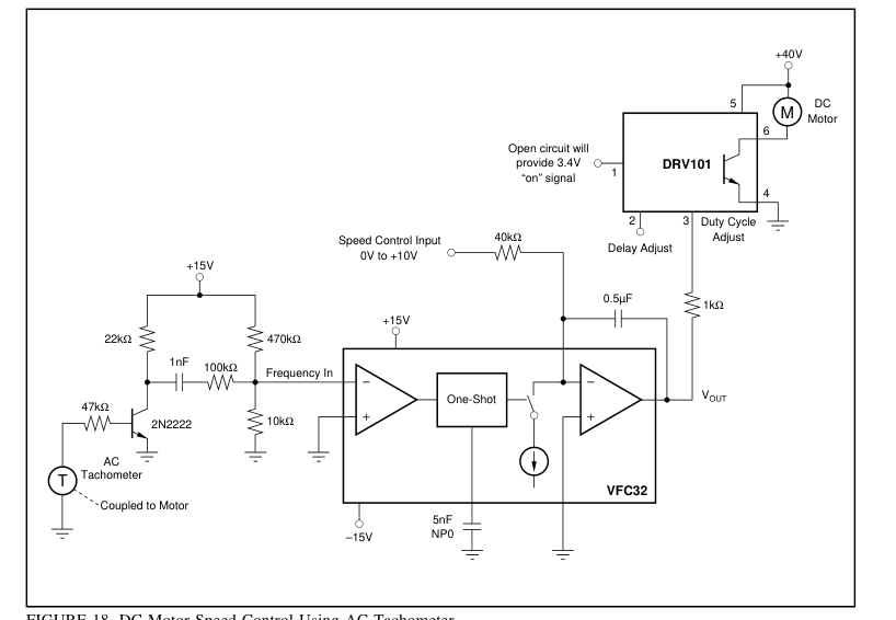
FIGURE 18. DC Motor Speed Control Using AC Tachometer.
Page 17
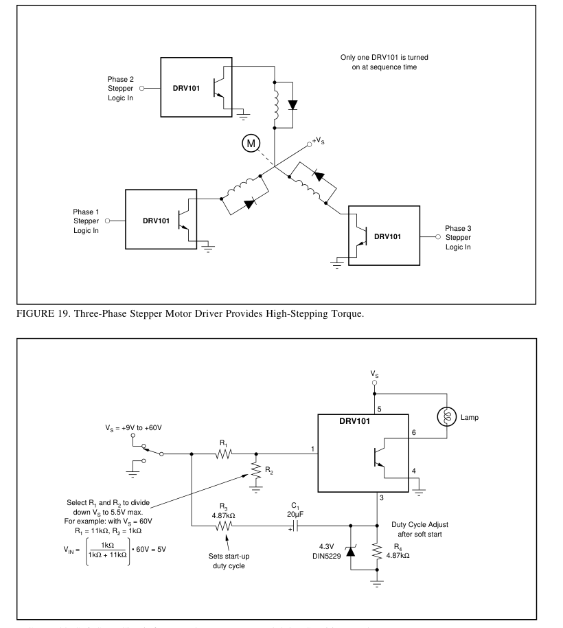
FIGURE 20. Soft-Start Circuit for Incandescent Lamps and Other Sensitive Loads.
Page 18
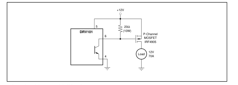
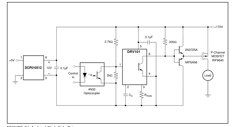
FIGURE 21. High Power, High-Side Driver.
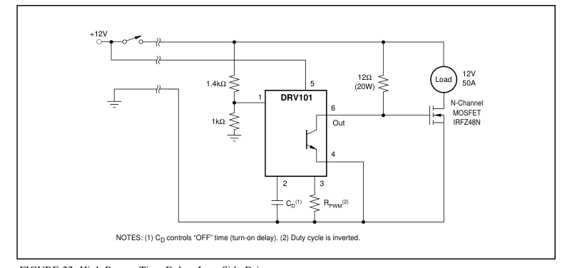
FIGURE 22. High Power, Time Delay, Low-Side Driver.
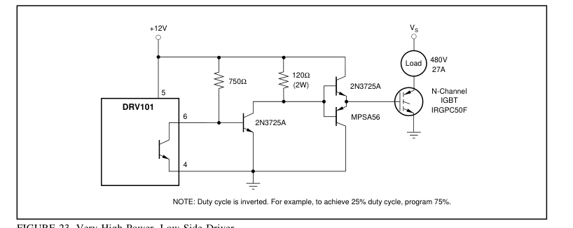
FIGURE 23. Very High Power, Low-Side Driver.
Page 19