
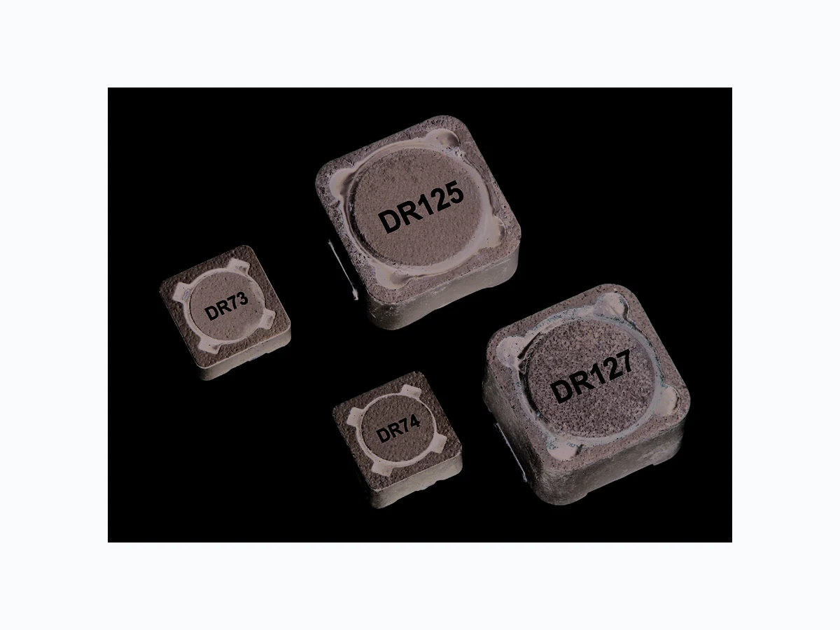
DR127-2R2 ETC2
Document overview
- Manufacturer or author: Provided By www.digicamel.com(FREE DATASHEET DOWNLOAD SITE)
- PDF pages: 11
Technical content
- Lead free, RoHS compliant
- 125°C maximum total operating temperature
- Four sizes of shielded drum core induc- tors
- Inductance range from 0.33μH to 1000μH
- Current range up to 56 amps peak
- Magnetic shielding
- Secure mounting
- Ferrite core material
Applications
- Computer, DVD players, and portable power devices
- LCD panels
- DC-DC converters
- Buck, boost, forward, and resonant converters
- Noise filtering and filter chokes Environmental data
- Storage temperature range (Component): -40°C to +125°C
- Operating temperature range: -40°C to +125°C (ambient + self-temperature rise)
- Solder reflow temperature: J-STD-020D compliant Packaging:
- Supplied in tape and reel packaging (per reel): - DR73 1350 - DR74 1100 - DR125 600 - DR127 350 Coiltronics DR Series High power density, high efficiency, shielded inductors Technical Data 4315 Effective April 2014 Supersedes December 2007 Coiltronics is now part of Eaton Same great products plus even more. The Coiltronics brand of magnetics (formerly of the Bussmann Division of Cooper Industries) is now part of Eaton’s Electrical Group, Electronics Division. Pb
www.eaton.com/elx Technical Data 4315 Effective April 2014 DR Series High power density, high efficiency, shielded inductors Product specifications 1. Open Circuit Inductance Test Parameters: 100kHz, 0.25Vrms, 0.0Adc. 2. RMS current for an approximate DT of 40°C without core loss. It is recommended that the temperature of the part not exceed 125°C. 3. Peak current for approximate 30% roll off at 20°C. 4. DCR limits @ 20°C. 5. Applied Volt-Time product (V-μS) across the inductor. This value represent the applied V-μSat 100kHz necessary to generate a core loss equal to 10% of the total losses for 40°C temperature rise. 6. Part number definition: DRxxx-yyy-R - DRxxx = product code and size, - yyy = inductance value in μH, - R = decimal point. If no R is present, third character = # of zeros - “-R” suffix = RoHS compliant Part Number Rated Inductance (μH) OCL1 ±20% (μH) Irms Amps Isat Amps Peak DCR4 (Ω) Typ. Volt-μSec5 Typ. DR73-821-R 820 821.7 0.27 0.28 3.93 103 DR73-102-R 1000 995.0 0.26 0.25 4.34 113
www.eaton.com/elx DR Series High power density, high efficiency, shielded inductors Technical Data 4315 Effective April 2014 1. Open Circuit Inductance Test Parameters: 100kHz, 0.25Vrms, 0.0Adc. 2. RMS current for an approximate DT of 40°C without core loss. It is recommended that the temperature of the part not exceed 125°C. 3. Peak current for approximate 30% roll off at 20°C. 4. DCR limits @ 20°C. 5. Applied Volt-Time product (V-μS) across the inductor. This value represent the applied V-μSat 100kHz necessary to generate a core loss equal to 10% of the total losses for 40°C temperature rise. 6. Part number definition: DRxxx-yyy-R - DRxxx = product code and size, - yyy = inductance value in μH, - R = decimal point. If no R is present, third character = # of zeros - “-R” suffix = RoHS compliant Part Number Rated Inductance (μH) OCL1 ±20% (μH) Irms Amps Isat Amps Peak DCR4 (Ω) Typ. Volt-μSec5 Typ. DR74-102-R 1000 1009 0.27 0.31 3.89 100 Product specifications
www.eaton.com/elx Technical Data 4315 Effective April 2014 DR Series High power density, high efficiency, shielded inductors Part Number Rated Inductance (μH) OCL1 ±20% (μH) Irms Amps Isat Amps Peak DCR4 (Ω) Typ. Volt-μSec5 Typ. DR125-471-R 470 473.1 0.87 1.02 0.718 102 DR125-681-R 680 679.8 0.70 0.85 1.10 122 DR125-821-R 820 828.0 0.60 0.77 1.49 135 DR125-102-R 1000 1008 0.57 0.70 1.69 149 DR125-472-R 4700 4720 0.268 0.32 7.53 322.4 DR125-124-R 120000 120630 0.060 0.069 150 1521 1. Open Circuit Inductance Test Parameters: 100kHz, 0.25Vrms, 0.0Adc. 2. RMS current for an approximate DT of 40°C without core loss. It is recommended that the temperature of the part not exceed 125°C. 3. Peak current for approximate 30% roll off at 20°C. 4. DCR limits @ 20°C. 5. Applied Volt-Time product (V-μS) across the inductor. This value represent the applied V-μSat 100kHz necessary to generate a core loss equal to 10% of the total losses for 40°C temperature rise. 6. Part number definition: DRxxx-yyy-R - DRxxx = product code and size, - yyy = inductance value in μH, - R = decimal point. If no R is present, third character = # of zeros - “-R” suffix = RoHS compliant Product specifications
www.eaton.com/elx DR Series High power density, high efficiency, shielded inductors Technical Data 4315 Effective April 2014 1. Open Circuit Inductance Test Parameters: 100kHz, 0.25Vrms, 0.0Adc. 2. RMS current for an approximate DT of 40°C without core loss. It is recommended that the temperature of the part not exceed 125°C. 3. Peak current for approximate 30% roll off at 20°C. 4. DCR limits @ 20°C. 5. Applied Volt-Time product (V-μS) across the inductor. This value represent the applied V-μSat 100kHz necessary to generate a core loss equal to 10% of the total losses for 40°C temperature rise. 6. Part number definition: DRxxx-yyy-R - DRxxx = product code and size, - yyy = inductance value in μH, - R = decimal point. If no R is present, third character = # of zeros - “-R” suffix = RoHS compliant Part Number Rated Inductance (μH) OCL1 ±20% (μH) Irms Amps Isat Amps Peak DCR4 (Ω) Typ. Volt-μSec5 Typ. DR127-471-R 470 467.1 0.85 1.68 0.861 117 DR127-681-R 680 676.7 0.76 1.39 1.08 141 DR127-821-R 820 818.1 0.65 1.27 1.47 155 DR127-102-R 1000 1005 0.61 1.14 1.66 172 Product specifications
DR Series High power density, high efficiency, shielded inductors Dimensions - mm DR73 Series BOTTOM VIEW 1.13 6.0 2.0 7.6 Max
7.6 Max
3.55 Max 8.50 RECOMMENDED PAD LAYOUT DR73 ### wllyy R TOP VIEW 2.50 3.25 SCHEMATIC 4.35 Max FRONT VIEW 1.13 2.0 7.6 Max 7.6 Max BOTTOM VIEW TOP VIEW 8.50 RECOMMENDED PAD LAYOUT 2.50 3.25 SCHEMATIC DR74 Series DR74 ### wllyy R 12.50 Max 6.00 Max DR125-### wwllyy R 4.90 Typ 2.05 Typ. 1 12.50 Max 5.50 3.85 13.80 RECOMMENDED PAD LAYOUT SCHEMATICTOP VIEWFRONT VIEWBOTTOM VIEW DR125 Series DR127-### wwllyy R12 18.00 Max 12.50 Max 4.90 Typ 2.05 Typ. 1 12.50 Max BOTTOM VIEW TOP VIEW SCHEMATIC 5.50 3.85 13.80 RECOMMENDED PAD LAYOUT FRONT VIEW DR127 Series ### = Inductance value per family chart wllyy and wwllyy = (date code) R = revision level
www.eaton.com/elx DR Series High power density, high efficiency, shielded inductors Technical Data 4315 Effective April 2014 Packaging information - mm A A SECTION A-A Ko Bo 2.00 ±0.1 4.00 Ø1.50 +0.1/-0.0 Ao ±0.3 7.50±0.1 1.75±0.10 Ø1.50 Min. 12.00 User direction of feed DR73 Series Supplied in tape and reel packaging, 1350 parts per reel,13" diameter reel. ACTUAL SIZE DR73 Ao=7.90mm Bo=7.90mm Ko=3.80mm DR73 ### wllyy R A A SECTION A-A Ko Bo 2.00 ±0.1 4.00 Ø1.50 +0.1/-0.0 Ao ±0.3 7.50±0.1 1.75±0.10 Ø1.50 Min. 12.00 User direction of feed DR74 Series Supplied in tape and reel packaging, 1100 parts per reel,13" diameter reel. ACTUAL SIZE DR74 Ao=7.90mm Bo=7.90mm Ko=4.70mm DR74 ### wllyy R A A SECTION A-A DR125-### wwllyy R +0.1/-0.0 1 min 4.0 2.0 16.00 1.7 11.5 +/-0.3 User direction of feed DR125 Series Supplied in tape and reel packaging, 600 parts per reel,13" diameter reel ACTUAL SIZE DR125Ao=13.0mm Bo=13.0mm Ko=6.30mm A A DR127-### wwllyy R SECTION A-A +0.1/-0.0 min 4.0 2.0 20.00 1.7 11.5 +/-0.3 User direction of feed DR127 Series Supplied in tape and reel packaging, 350 parts per reel,13" diameter reel. ACTUAL SIZE DR127Ao=13.0mm Bo=13.0mm Ko=8.30mm
www.eaton.com/elx Technical Data 4315 Effective April 2014 DR Series High power density, high efficiency, shielded inductors Inductance characteristics OCL vs I sat DR73 100 02 04 06 08 01 00 120 140 160 % of Isat OCL (%) OCL vs I sat DR74 100 02 04 06 08 01 00 120 140 160 180 % of Isat OCL (%)
www.eaton.com/elx DR Series High power density, high efficiency, shielded inductors Technical Data 4315 Effective April 2014 Inductance characteristics OCL vs I sat DR125 100 01 02 03 04 05 06 07 08 09 01 00 110 120 130 140 150 % of Isat OCL (%) OCL vs I sat DR127 100 01 02 03 04 05 06 07 08 09 01 00 1101 20 1301 40 150 % Isat OCL (%)
www.eaton.com/elx Technical Data 4315 Effective April 2014 DR Series High power density, high efficiency, shielded inductors Core loss 10 100 1000 % of Applied Volt-µSecond 0 kHz 0 kHz 100 kHz kHz kHz Irms Derating with Core Loss 8060403020 200 300 4006 00 800 % of Losses from Irms (max)
www.eaton.com/elx Eaton is a registered trademark. All other trademarks are property of their respective owners. Eaton’s Electrical Group Electronics Division 1 14 Old State Road Ellisville, MO 63021 United States www.eaton.com/elx © 2014 Eaton All Rights Reserved Publication No. 4315 — BU-SB141 12 April 2014 Temperature t tP ts TC -5°C Time 25°C to Peak Time 25°C Tsmin Tsmax TL TP Preheat A Max. Ramp Up Rate = 3°C/s Max. Ramp Down Rate = 6°C/s Table 1 - Standard SnPb Solder (Tc) Volume Volume Packagem m3 mm3 Thickness <350 >_350 <2.5mm 235°C 220°C Table 2 - Lead (Pb) Free Solder (Tc) Volume Volume Volume Packagem m3 mm3 mm3 Thickness <350 350 - 2000 >2000 <1.6mm 260°C 260°C 260°C 1.6 – 2.5mm 260°C 250°C 245°C >2.5mm 250°C 245°C 245°C Reference JDEC J-STD-020D Profile Feature Standard SnPb Solder Lead (Pb) Free Solder Preheat and Soak • Temperature min.( Tsmin) 100°C 150°C
- Temperature max. (Tsmax) 150°C 200°C
- Time (Tsmin to Tsmax) (ts) 60-120 Seconds 60-120 Seconds Average ramp up rate Tsmax to Tp 3°C/ Second Max. 3°C/ Second Max. Liquidous temperature (TL) 183°C 217°C Time at liquidous (tL) 60-150 Seconds 60-150 Seconds Peak package body temperature (TP)* Table 1T able 2 Time (tp) within 5 °C of the specified classification temperature (Tc) 20 Seconds 30 Seconds** Average ramp-down rate (Tp to Tsmax) 6°C/ Second Max. 6°C/ Second Max. Time 25°C to Peak Temperature 6 Minutes Max. 8 Minutes Max. * Tolerance for peak profile temperature (Tp) is defined as a supplier minimum and a user maximum. ** Tolerance for time at peak profile temperature (tp) is defined as a supplier minimum and a user maximum. Solder reflow profile North America Eaton’s Electrical Group Electronics Division
1225 Broken Sound Parkway NW
Boca Raton, FL 33487-3533 Tel: 1-561-998-4100 Fax: 1-561-241-6640 Toll Free: 1-888-414-2645 Eaton’s Electrical Group Electronics Division P .O. Box 14460 St. Louis, MO 63178-4460 Tel: 1-636-394-2877 Fax: 1-636-527-1607 Europe Eaton’s Electrical Group Electronics Division Burton-on-the-Wolds Leicestershire, LE 12 5th UK Phone: +44 (0) 1509 882 600 Fax: +44 (0) 1509 882 786 Eaton’s Electrical Group Electronics Division Avda Santa Eulalia, 290 Terrassa, Barcelona 08223 Spain Phone: +34-93-736-2813 Fax: +34-93-783-5055 Asia Pacific Eaton’s Electrical Group Electronics Division No.2, #06-01 Serangoon North Avenue 5 Singapore 554911 Tel: +65 6645 9888 Fax: +65 6728 3155 The only controlled copy of this Data Sheet is the electronic read-only version located on the Bussmann Network Drive. All other copies of this document are by definition uncontrolled. This bulletin is intended to clearly present comprehensive product data and provide technical information that will help the end user with design applications. Bussmann reserves the right, without notice, to change design or construction of any products and to discontinue or limit distribution of any products. Bussmann also reserves the right to change or update, without notice, any technical information contained in this bulletin. Once a product has been selected, it should be tested by the user in all possible applications. Life Support Policy: Bussmann does not authorize the use of any of its products for use in life support devices or systems without the express written approval of an officer of the Company. Life support systems are devices which support or sustain life, and whose failure to perform, when properly used in accordance with instructions for use provided in the labeling, can be reasonably expected to result in significant injury to the user. DR Series High power density, high efficiency, shielded inductors Technical Data 4315 Effective April 2014