
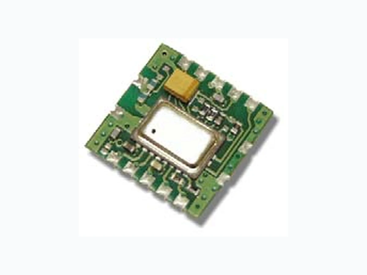
DR5000 MURATA
Document overview
- Manufacturer or author: Provided By www.digicamel.com(FREE DATASHEET DOWNLOAD SITE)
- PDF pages: 4
Technical content
www.RFM.com E-mail: info@rfm.com Page 1 of 4 ©2008 by RF Monolithics, Inc. - 4/8/08 Characteristic Sym Notes Minimum Typical Maximum Units Operating Frequency fO 916.3 916.7 MHz Modulation Type OOK Data Rate 2.4 19.2 kbps Receiver Performance (OOK @ 2.4 kbps) Input Current, 3 Vdc Supply IR 1.8 mA Input Signal for 10-4 BER, 25 C -100 dBm Rejection, ±30 MHz RREJ 55 dB Sleep to Receive Switch Time(100 ms sleep, -85 dBm signal) tSR 3 200 µs Sleep Mode Current IS 5 µA Power Supply Voltage Range VCC 2.7 3.5 Vdc Operating Ambient Temperature T A -20 +65 °C
- Designed for Short-Range Wireless Data Communications Supports up to 19.2 kbps Encoded Data Transmissions 3 V, Low Current Operation plus Sleep Mode Ready to Use OEM Module The DR5000 receiver module is ideal for short-range wireless data applications where robust operation, small size and low power consumption are required. The DR5000 utilizes RFM’s RX6000 amplifier-sequenced hybrid (ASH) architecture to achieve this unique blend of characteristics. The receiver RX6000 is sensitive and stable. A wide dynamic range log detector provi des robust performance in the presence of on-channel interference or noise. Two stages of SAW filtering provide excellent receiver out-of -band rejection. The DR5000 includes the RX6000 plus all configuration com ponents in a ready-to-use PCB assembly excellent for prototyping and intermediate volume production runs. Absolute Maximum Ratings Rating Value Units Power Supply and All Input/Output Pins -0.3 to +4.0 V Non-Operating Case Temperature -50 to +100 °C Soldering Temperature (10 seconds) 230 °C
916.50 MHz
.70 .25 .20 .165 .70 .10 DR5000 Outline Drawing Dimensions in inches DR5000 Pin Out RF GND RFIO AGC/VCC PK DET NC RX BBO RX DATA CTR0 CTR1 GND VCC LPF ADJ 1314 GND GND
www.RFM.com E-mail: info@rfm.com Page 2 of 4 ©2008 by RF Monolithics, Inc. - 4/8/08 Pin Desciptions Pin Name Description
1 AGC/VCC
This pin is connected directly to the receiver AGCCAP pin. To disable AGC operation, this pin is tied to VCC. To enable AGC operation, a capacitor is placed between this pin and ground. Th is pin controls the AGC reset operation. A capacitor between this pin and ground sets the minimum time the AGC will hold-in onc e it is engaged. The hold-in time is set to avoid AGC chat- tering. For a given hold-in time tAGH, the capacitor value CAGC is: CAGC = 19.1* tAGH, where tAGH is in µs and CAGC is in pF A ±10% ceramic capacitor should be used at this pin. The value of CAGC given above provides a hold-in time between tAGH and 2.65* tAGH, depending on operating voltage, temperature, etc. The hold-in time is chosen to allow the AGC to ride through the longest run of zero bits that can occur in a received data st ream. The AGC hold-in time can be greater than the peak detector decay time, as discussed below. However, the AGC hold-in time should not be set too long, or the receiver will be slow in returning to full sensitivity once the AGC is engaged by noise or interference. T he use of AGC is optional when using OOK modulation with data pulses of at least 30 µs. Active or latche d AGC operation is required for ASK modulation and/or for data pulses of less than 30 µs. The AGC can be latched ON onc e engaged by connecting a 150 K resistor between this pin and ground, instead of a capacitor. AGC operation depends on a functioning peak detector, as discussed below. The AGC capacitor is discharged in the receiver power-down (sleep) mode. Note that provisions are made on the circuit board to install a jumper between this pin and the junction of C2 and L3. Installing the jumper allows either this pin or Pin 9 to be used for the Vcc supply when AGC operation is not required. 2P K D E T This pin is connected directly to the receiver PKDET pin. This pin controls the peak detector operation. A capacitor between this pin and ground sets the peak detector attack and decay times, which have a fixed 1:1000 ratio. For most applications, the attack time constant should be set to 6.4 ms with a 0.027 µF capacitor to ground. (This matches the peak detector decay time constant to the time constant of the 0.1 µF coupling capacitor C3.) A ±10% ceramic capacitor should be used at this pin. The peak detector is used to drive the "dB-below-peak" data slic er and the AGC release function. The AGC hold-in time can be extended beyond the peak detector decay time with the AGC capa citor, as discussed above. Where low data rates and OOK modulation are used, the "dB-below-peak" data slicer and the AG C are optional. In this case, the PKDET pin can be left uncon- nected, and the AGC pin can be connected to VCC to reduce the number of external components needed. The peak detector capacitor is discharged in the receiver power-down (sleep) mode. See the description of Pin 3 below for further information.
3 RX BBO
This pin is connected directly to the receiver BBOUT pin. On the circuit board, BBOUT also drives the receiver CMPIN pin through C3, a 0.1 µF coupling capacitor (t BBC = 6.4 ms). RX BBO can also be used to drive an external data recovery process (DSP, etc.). The nominal output impedance of this pin is 1 K. The RX BBO signal changes about 10 mV/dB, with a peak-to- peak signal level of up to 675 mV. The signal at RX BBO is riding on a 1.1 Vdc value that varies somewhat with supply voltage and temperature, so it should be coupled through a capacitor to an external load. A load impedance of 50 K to 500 K in parallel with no more than 10 pF is recommended. Note the AGC reset function is driven by the signal applied to CMPIN through C3. When the receiver is in power-down (sleep) the output impedance of this pin becomes very high, preserving the charge on the coupling capacitor(s). The value of C3 on the circuit board has been chosen to match typical data encoding schemes at 2.4 kbps. If C3 is modified to support higher data rates and/or di fferent data encoding schemes and PK DET is being used, make the value of the peak detector capacitor about 1/3 the value of C3. 4R X D A T A RX DATA is connected directly to the receiver data output pin, RXDATA. This pin will drive a 10 pF, 500 K parallel load. The peak current available from this pin increases with the receiv er low-pass filter cutoff frequency. In the power-down (sleep) or receive mode, this pin becomes high impedanc e. If required, a 1000 K pull-up or pull- down resistor can be used to establish a definite logic state when this pin is high impedance (do not c onnect the pull-up resistor to a supply voltage higher than 3.5 V dc or the receiver will be damaged). Th is pin must be buffered to successfully drive low-impedance loads. 5N C 6, 7 GND 8L P F A D J This pin is the receiver low-pass filter bandwidth adjust, and is connected directly to the receiver LPFADJ pin. R6 on the circuit board (330 K) is connected between LPFADJ and ground will be in pa rallel with any external resistor connected to LPF ADJ. The filter bandwidth is set by the parallel resistance of R6 and the external resistor (if used). The equivalent resistor value can range from 330 K to 820 ohms, providing a filter 3 dB bandwidth f LPF from 4.4 kHz to 1.8 MHz. The 3 dB filter bandwidth is determined by: fLPF = 1445/ (330*RLPF/(330 + RLPF)), where RLPF is in kilohms, and fLPF is in kHz A ±5% resistor should be used to set the filter bandwidth . This will provide a 3 dB filter bandwidth between f LPF and 1.3* fLPF with variations in supply voltage, temperature, etc. The filter provides a three-pole, 0.05 degree equiripple phase response. The peak drive current available from RXDATA increases in proportion to the filter bandwidth setting. As shipped, the receiver mod- ule is set up for nominal 2.4 kbps operation. An external resistor can be added between Pin 8 and ground to support higher data rates. Preamble training times will not be decreased, however, unless C3 is replaced with a smaller capacitor value (see additional information on data rate adjustments.
www.RFM.com E-mail: info@rfm.com Page 3 of 4 ©2008 by RF Monolithics, Inc. - 4/8/08 Data Out
3 Vdc
2.4 kbps Application Circuit 12345 89101112 DR3000 DR5000 Data Out 19.2 kbps Application Circuit 12345 89101112 33 kDR5000 Pin Name Description 9V C C This is the positive supply voltage pin for the module. The operati ng voltage range is 2.7 to 3.5 Vdc. It is also possible to u se Pin 1 as the Vcc input. Please refer to the Pin 1 description above. 10 GND This is the supply voltage return pin.
11 CTR1
CTR1 is connected to the CNTRL1 control pin on the receiver. CTR1 and CTR0 select the transceiver operating modes. CTR1 and CTR0 both high place the unit in the receive mode. CTR1 and CTR0 both low place the unit in the power-down (sleep) mode. CTR1 is a high-impedance input (CMOS compatible). This pin must be held at a logic level; it cannot be left uncon- nected. At turn on, the voltage on this pin and CTR0 should ri se with VCC until VCC reaches 2.7 Vdc (receive mode). Thereaf- ter, any mode can be selected.
12 CTR0
CTR0 is connected to the CNTRL0 control pi n on the receiver CTR0 is used with CTR1 to control the operating modes of the receiver. CTR0 is a high-impedance input (CMOS compatible). This pin must be held at a logic level; it cannot be left uncon- nected. At turn on, the voltage on this pin and CTR1 should ri se with VCC until VCC reaches 2.7 Vdc (receive mode). Thereaf- ter, any mode can be selected. 13 RFIO RFIO is the RF input/output pin. A matching circuit for a 50 ohm load (antenna) is implemented on the circuit board between this pin and the receiver SAW filter transducer.
14 RF GND
This pin is the RF ground (return) to be used in conjunction with the RFIO pin. Fo r example, when connecting the transceiver module to an external antenna, the coaxial cable ground is connected this pin and the coaxial cable center conductor is con- nected to RFIO.
www.RFM.com E-mail: info@rfm.com Page 4 of 4 ©2008 by RF Monolithics, Inc. - 4/8/08 Note: Preliminary specifications, subject to change without notice. R1 R2 C4 C5 ASH Receiver CTR0 (12) CTR1 (11) VCC (9) LPF ADJ (8) GND (6, 7, 10) RFIO (13) RF GND (14) AGC/VCC (1) PK DET (2) RX BBO (3) RX DATA (4) DR5000 Schematic