
 Download PDF
DMT10H009LK3 ISC
Document overview
- PDF pages: 2
Technical content
Page 1
isc N-Channel MOSFET Transistor
DMT10H009LK3
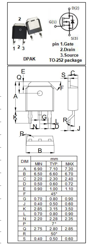
FEATURES
- Drain Current -ID= 90A@ TC=25℃
- Drain Source Voltage -VDSS= 100V(Min)
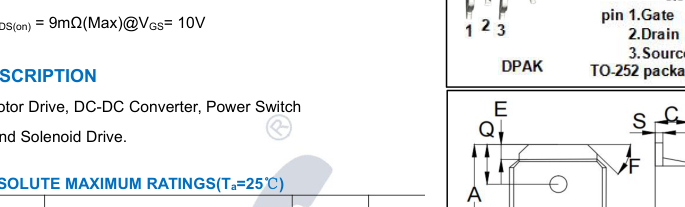
- Static Drain-Source On-Resistance
| SYMBOL | PARAMETER | VALUE | UNIT |
|---|---|---|---|
| V DSS | Drain-Source Voltage | 100 | V |
| V GS | Gate-Source Voltage-Continuous | ±20 | V |
| I D | Drain Current-Continuous | 90 | A |
| I DM | Drain Current-Single Pulse | 360 | A |
| P D | Total Dissipation @T =25℃ C | 114 | W |
| TJ | Max. Operating Junction Temperature | 150 | ℃ |
| Tstg | Storage Temperature | -55~150 | ℃ |

| SYMBOL | PARAMETER | MAX | UNIT |
|---|---|---|---|
| Rth j-c | Thermal Resistance, Junction to Case | 1.1 | ℃/W |
www.iscsemi.com
Page 2
isc N-Channel MOSFET Transistor
DMT10H009LK3
ELECTRICAL CHARACTERISTICS(TC=25℃ unless otherwise specified)
| SYMBO L | PARAMETER | CONDITIONS | MIN | TYP. | MAX | UNIT |
|---|---|---|---|---|---|---|
| V (BR)DSS | Drain-Source Breakdown Voltage | V = 0V; I = 1mA GS D | 100 | -- | -- | V |
| I DSS | Zero Gate Voltage Drain Current | V = 80V; V = 0V DS GS | -- | -- | 1.0 | μA |
| I GSS | Gate-Body Leakage Current | V = ±20V;V = 0V GS DS | -- | -- | ±100 | nA |
| V GS(th) | Gate Threshold Voltage | V = V ; I = 0.25A DS GS D | 1.0 | -- | 3.0 | V |
| R DS(on) | Drain-Source On-Resistance | V = 10V; I = 20A GS D | -- | -- | 9 | mΩ |
| V = 4.5V; I = 5A GS D | -- | -- | 13 | mΩ | ||
| V SD | Forward On-Voltage | I = 20A; V = 0V S GS | -- | -- | 1.3 | V |
| t d(on) | Turn-on Delay Time | V = 50V, DD I = 20A, D R = 3Ω G | -- | 5.5 | -- | ns |
| t r | Turn-on Rise Time | -- | 10.5 | -- | ||
| t d(off) | Turn-off Delay Time | -- | 28.2 | -- | ||
| t f | Turn-off Fall Time | -- | 15 | -- |